1997 SSANGYONG KORANDO lock
[x] Cancel search: lockPage 1111 of 2053

AUTOMATIC TRANSMISSION 5A-17
SSANGYONG MY2002
Bands
The transmission utilizes two bands, the B1 band
(sometimes known as the 2-4 band), and the B2 band
(sometimes known as the low-reverse band).
The B1 band is a flexible band which is engaged by
the front servo piston. B1 is activated in second and
fourth gear. When activated B1 prevents the reverse
sun gear from rotating by holding the C3 clutch
assembly stationary. In second gear only the outerarea of the apply piston is utilized. In fourth gear both
areas are utilized for greater clamping force.
The B2 band is a solid band which is engaged by the
rear servo piston. B2 is activated in Park, Reverse,
Neutral and Manual 1. When activated B2 prevents
the planet carrier assembly from rotating. In Manual 1
only the inner area of the apply piston is utilized. In
Park, Reverse and Neutral, both areas are utilized for
greater clamping force.
One Way Clutches
The transmission uses two OWCs, the 1-2 OWC and
the 3-4 OWC. (Note that a third OWC is located in the
torque converter, also known as a sprag.)
The 1-2 OWC is located between the planetary carrier
assembly and the center support. This allows the carrier
to rotate around the center support in one direction
only. The one way clutch is engaged only in Drive 1.
This 3-4 OWC is located between the C4 and the C2
clutch assemblies. This allows the C2 clutch to drive
the forward sun gear in first, second and third gears
but unlocks in fourth gear and during overrun.
Planetary Gear Set
The planetary gear set used in the transmission is a
conventional six pinion Ravigneaux compound gear
set.
Parking Mechanism
When Park is selected the manual lever extends the
park rod rearwards to engage the parking pawl. The
pawl will engage the external teeth on the ring gear
thus locking the output shaft to the transmission case.
When Park is not selected a return spring holds the
parking pawl clear of the output shaft, preventing
accidental engagement of Park.
KAA5A300 KAA5A280KAA5A290
Page 1112 of 2053
5A-18 AUTOMATIC TRANSMISSION
SSANGYONG MY2002
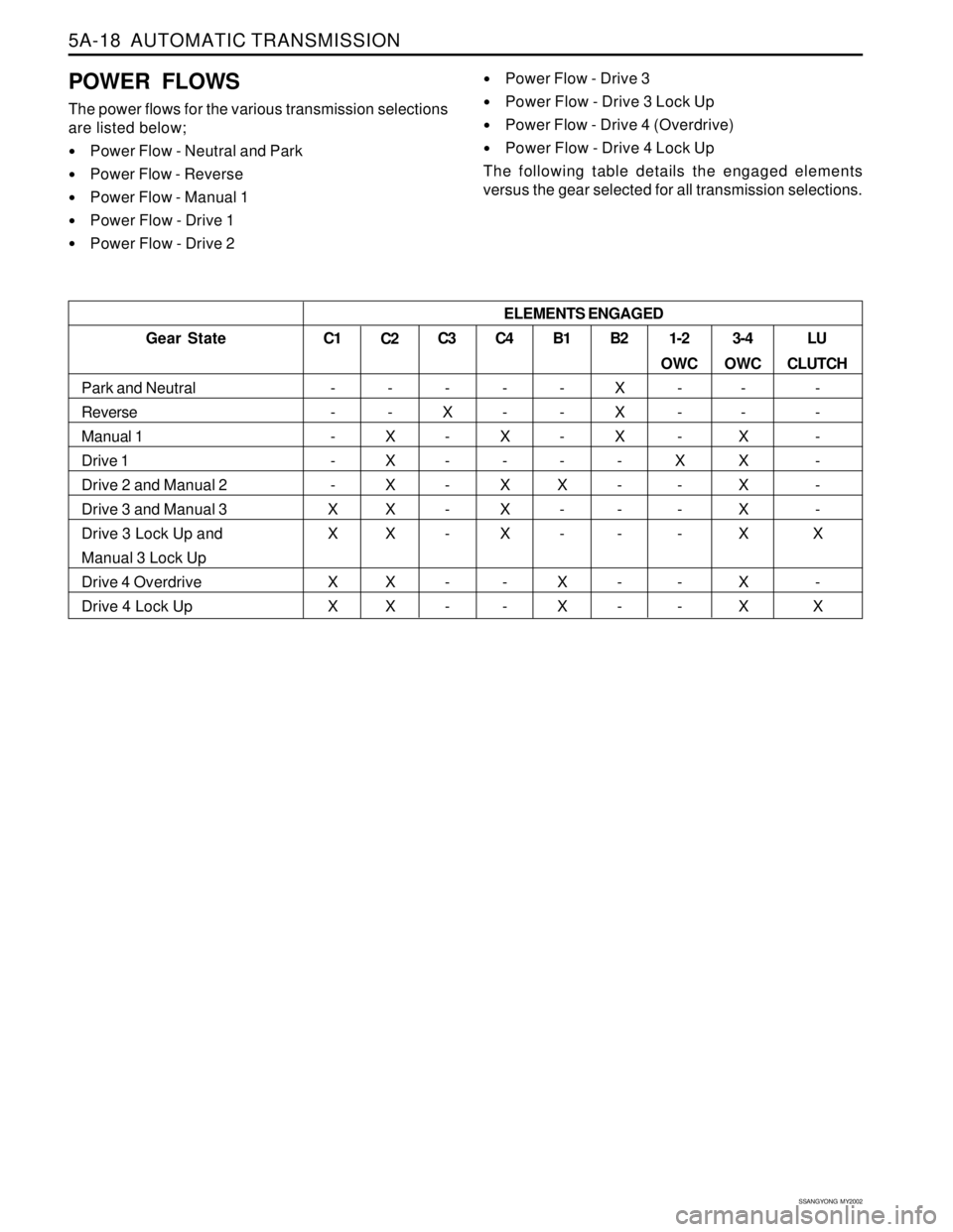
POWER FLOWS
The power flows for the various transmission selections
are listed below;
Power Flow - Neutral and Park
Power Flow - Reverse
Power Flow - Manual 1
Power Flow - Drive 1
Power Flow - Drive 2
Power Flow - Drive 3
Power Flow - Drive 3 Lock Up
Power Flow - Drive 4 (Overdrive)
Power Flow - Drive 4 Lock Up
The following table details the engaged elements
versus the gear selected for all transmission selections.
C1
-
-
-
-
-
X
X
X
X1-2
OWC
-
-
-
X
-
-
-
-
-3-4
OWC
-
-
X
X
X
X
X
X
X B2
X
X
X
-
-
-
-
-
- B1
-
-
-
-
X
-
-
X
X
Gear State
Park and Neutral
Reverse
Manual 1
Drive 1
Drive 2 and Manual 2
Drive 3 and Manual 3
Drive 3 Lock Up and
Manual 3 Lock Up
Drive 4 Overdrive
Drive 4 Lock UpC2
-
-
X
X
X
X
X
X
XC3
-
X
-
-
-
-
-
-
-C4
-
-
X
-
X
X
X
-
-LU
CLUTCH
-
-
-
-
-
-
X
-
X ELEMENTS ENGAGED
Page 1115 of 2053
AUTOMATIC TRANSMISSION 5A-21
SSANGYONG MY2002
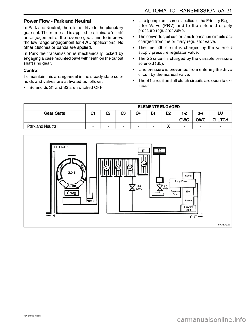
Power Flow - Park and Neutral
In Park and Neutral, there is no drive to the planetary
gear set. The rear band is applied to eliminate ‘clunk’
on engagement of the reverse gear, and to improve
the low range engagement for 4WD applications. No
other clutches or bands are applied.
In Park the transmission is mechanically locked by
engaging a case mounted pawl with teeth on the output
shaft ring gear.
Control
To maintain this arrangement in the steady state sole-
noids and valves are activated as follows:
Solenoids S1 and S2 are switched OFF.
Line (pump) pressure is applied to the Primary Regu-
lator Valve (PRV) and to the solenoid supply
pressure regulator valve.
The converter, oil cooler, and lubrication circuits are
charged from the primary regulator valve.
The line 500 circuit is charged by the solenoid
supply pressure regulator valve.
The S5 circuit is charged by the variable pressure
solenoid (S5).
Line pressure is prevented from entering the drive
circuit by the manual valve.
The B1 circuit and all clutch circuits are open to ex-
haust.
C1
-C2
-C3
-C4
-B1
-B2
X1-2
OWC
-3-4
OWC
-LU
CLUTCH
- Gear State
Park and Neutral
ELEMENTS ENGAGED
KAA5A320
Page 1117 of 2053
AUTOMATIC TRANSMISSION 5A-23
SSANGYONG MY2002
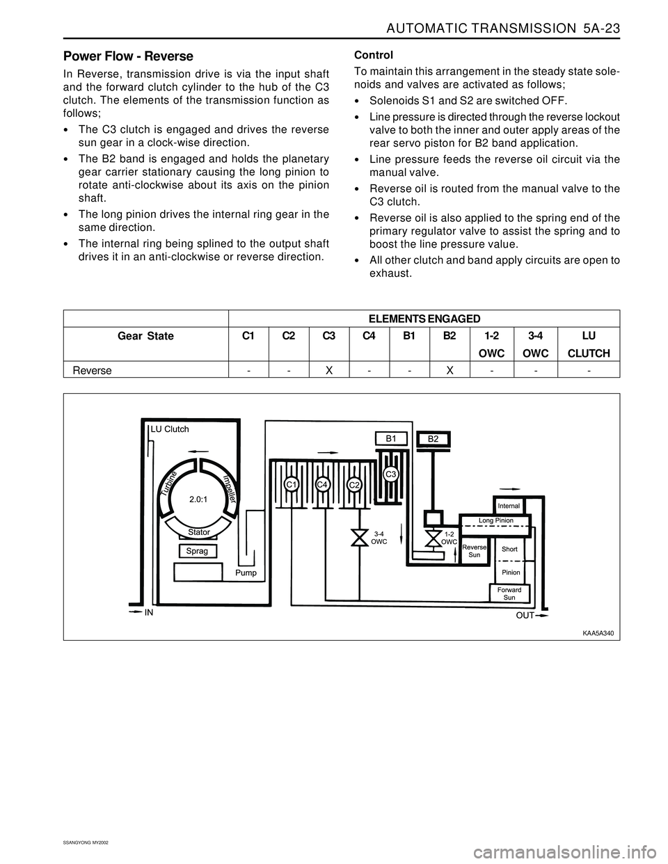
Power Flow - Reverse
In Reverse, transmission drive is via the input shaft
and the forward clutch cylinder to the hub of the C3
clutch. The elements of the transmission function as
follows;
The C3 clutch is engaged and drives the reverse
sun gear in a clock-wise direction.
The B2 band is engaged and holds the planetary
gear carrier stationary causing the long pinion to
rotate anti-clockwise about its axis on the pinion
shaft.
The long pinion drives the internal ring gear in the
same direction.
The internal ring being splined to the output shaft
drives it in an anti-clockwise or reverse direction.Control
To maintain this arrangement in the steady state sole-
noids and valves are activated as follows;
Solenoids S1 and S2 are switched OFF.
Line pressure is directed through the reverse lockout
valve to both the inner and outer apply areas of the
rear servo piston for B2 band application.
Line pressure feeds the reverse oil circuit via the
manual valve.
Reverse oil is routed from the manual valve to the
C3 clutch.
Reverse oil is also applied to the spring end of the
primary regulator valve to assist the spring and to
boost the line pressure value.
All other clutch and band apply circuits are open to
exhaust.
C3
X
Gear State
ReverseC1
-C2
-C4
-B1
-B2
X1-2
OWC
-3-4
OWC
-LU
CLUTCH
- ELEMENTS ENGAGED
KAA5A340
Page 1119 of 2053
AUTOMATIC TRANSMISSION 5A-25
SSANGYONG MY2002
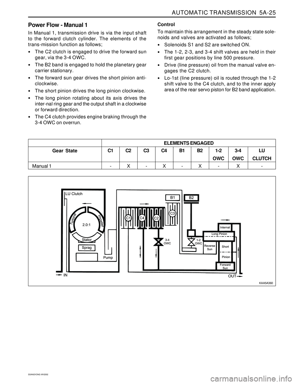
Power Flow - Manual 1
In Manual 1, transmission drive is via the input shaft
to the forward clutch cylinder. The elements of the
trans-mission function as follows;
The C2 clutch is engaged to drive the forward sun
gear, via the 3-4 OWC.
The B2 band is engaged to hold the planetary gear
carrier stationary.
The forward sun gear drives the short pinion anti-
clockwise.
The short pinion drives the long pinion clockwise.
The long pinion rotating about its axis drives the
inter-nal ring gear and the output shaft in a clockwise
or forward direction.
The C4 clutch provides engine braking through the
3-4 OWC on overrun.Control
To maintain this arrangement in the steady state sole-
noids and valves are activated as follows;
Solenoids S1 and S2 are switched ON.
The 1-2, 2-3, and 3-4 shift valves are held in their
first gear positions by line 500 pressure.
Drive (line pressure) oil from the manual valve en-
gages the C2 clutch.
Lo-1st (line pressure) oil is routed through the 1-2
shift valve to the C4 clutch, and to the inner apply
area of the rear servo piston for B2 band application.
ELEMENTS ENGAGED
Gear State
Manual 1C1
-C2
XC3
-C4
XB1
-B2
X1-2
OWC
-3-4
OWC
XLU
CLUTCH
-
KAA5A360
Page 1121 of 2053
AUTOMATIC TRANSMISSION 5A-27
SSANGYONG MY2002
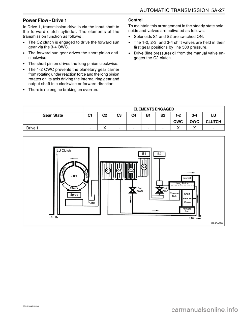
Power Flow - Drive 1
In Drive 1, transmission drive is via the input shaft to
the forward clutch cylinder. The elements of the
transmission function as follows :
The C2 clutch is engaged to drive the forward sun
gear via the 3-4 OWC.
The forward sun gear drives the short pinion anti-
clockwise.
The short pinion drives the long pinion clockwise.
The 1-2 OWC prevents the planetary gear carrier
from rotating under reaction force and the long pinion
rotates on its axis driving the internal ring gear and
output shaft in a clockwise or forward direction.
There is no engine braking on overrun.Control
To maintain this arrangement in the steady state sole-
noids and valves are activated as follows:
Solenoids S1 and S2 are switched ON.
The 1-2, 2-3, and 3-4 shift valves are held in their
first gear positions by line 500 pressure.
Drive (line pressure) oil from the manual valve en-
gages the C2 clutch.
Gear State
Drive 1C1
-
C2
XC3
-C4
-B1
-B2
-1-2
OWC
X3-4
OWC
XLU
CLUTCH
- ELEMENTS ENGAGED
KAA5A380
Page 1123 of 2053
AUTOMATIC TRANSMISSION 5A-29
SSANGYONG MY2002
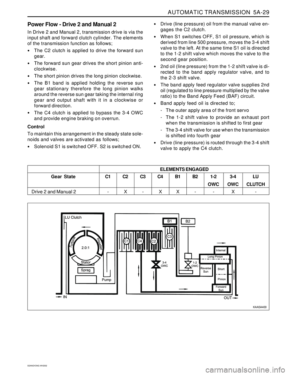
Power Flow - Drive 2 and Manual 2
In Drive 2 and Manual 2, transmission drive is via the
input shaft and forward clutch cylinder. The elements
of the transmission function as follows;
The C2 clutch is applied to drive the forward sun
gear.
The forward sun gear drives the short pinion anti-
clockwise.
The short pinion drives the long pinion clockwise.
The B1 band is applied holding the reverse sun
gear stationary therefore the long pinion walks
around the reverse sun gear taking the internal ring
gear and output shaft with it in a clockwise or
forward direction.
The C4 clutch is applied to bypass the 3-4 OWC
and provide engine braking on overrun.
Control
To maintain this arrangement in the steady state sole-
noids and valves are activated as follows;
Solenoid S1 is switched OFF. S2 is switched ON.
Drive (line pressure) oil from the manual valve en-
gages the C2 clutch.
When S1 switches OFF, S1 oil pressure, which is
derived from line 500 pressure, moves the 3-4 shift
valve to the left. At the same time S1 oil is directed
to the 1-2 shift valve which moves the valve to the
second gear position.
2nd oil (line pressure) from the 1-2 shift valve is di-
rected to the band apply regulator valve, and to
the 2-3 shift valve.
The band apply feed regulator valve supplies 2nd
oil (regulated to line pressure multiplied by the valve
ratio) to the Band Apply Feed (BAF) circuit.
Band apply feed oil is directed to;
- The outer apply area of the front servo
- The 1-2 shift valve to provide an exhaust port
when the transmission is shifted to first gear
- The 3-4 shift valve for use when the transmission
is shifted into fourth gear
Drive (line pressure) is routed through the 3-4 shift
valve to apply the C4 clutch.
Gear State
Drive 2 and Manual 2ELEMENTS ENGAGEDC1
-C2
XC3
-C4
XB1
XB2
-1-2
OWC
-3-4
OWC
XLU
CLUTCH
-
KAA5A400
Page 1125 of 2053
AUTOMATIC TRANSMISSION 5A-31
SSANGYONG MY2002
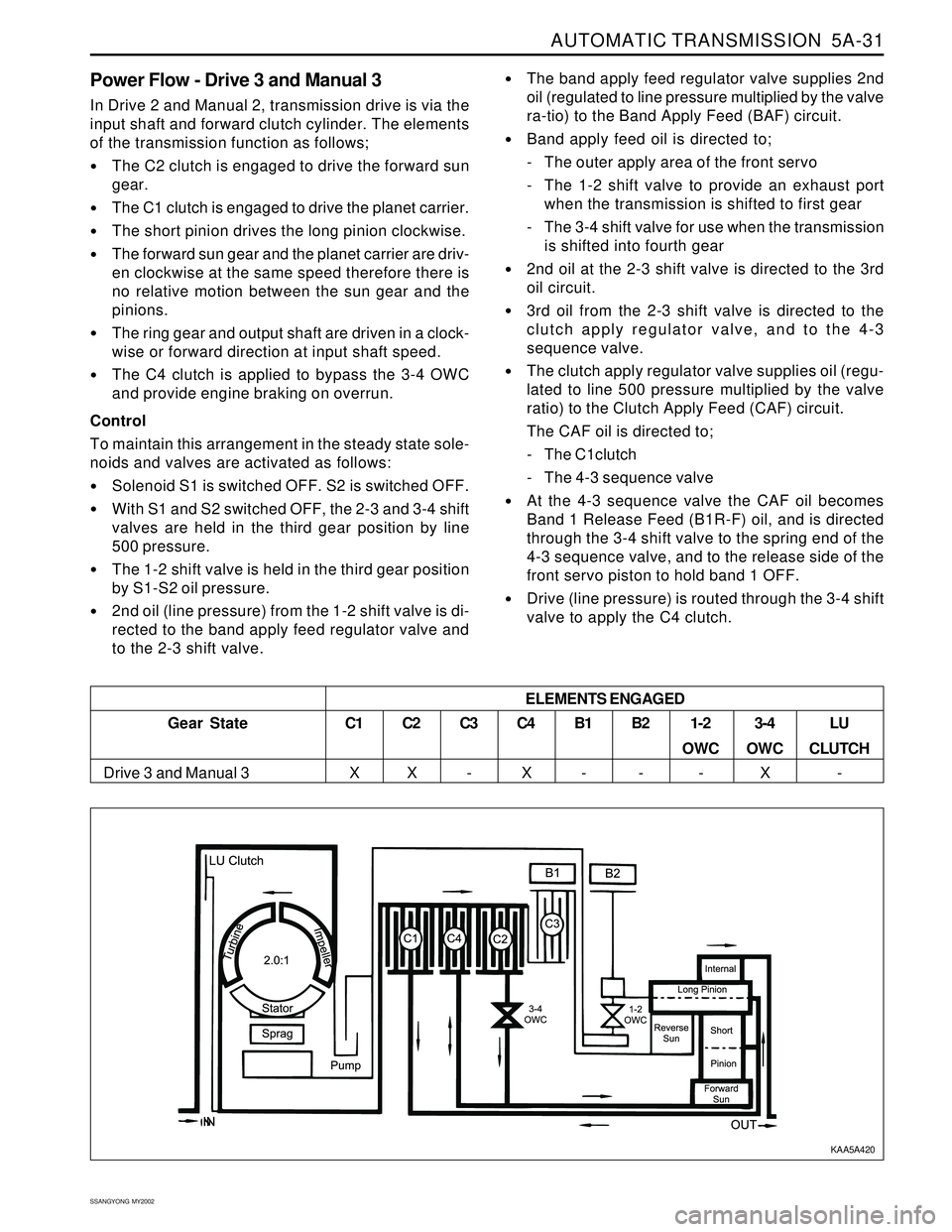
Power Flow - Drive 3 and Manual 3
In Drive 2 and Manual 2, transmission drive is via the
input shaft and forward clutch cylinder. The elements
of the transmission function as follows;
The C2 clutch is engaged to drive the forward sun
gear.
The C1 clutch is engaged to drive the planet carrier.
The short pinion drives the long pinion clockwise.
The forward sun gear and the planet carrier are driv-
en clockwise at the same speed therefore there is
no relative motion between the sun gear and the
pinions.
The ring gear and output shaft are driven in a clock-
wise or forward direction at input shaft speed.
The C4 clutch is applied to bypass the 3-4 OWC
and provide engine braking on overrun.
Control
To maintain this arrangement in the steady state sole-
noids and valves are activated as follows:
Solenoid S1 is switched OFF. S2 is switched OFF.
With S1 and S2 switched OFF, the 2-3 and 3-4 shift
valves are held in the third gear position by line
500 pressure.
The 1-2 shift valve is held in the third gear position
by S1-S2 oil pressure.
2nd oil (line pressure) from the 1-2 shift valve is di-
rected to the band apply feed regulator valve and
to the 2-3 shift valve.
The band apply feed regulator valve supplies 2nd
oil (regulated to line pressure multiplied by the valve
ra-tio) to the Band Apply Feed (BAF) circuit.
Band apply feed oil is directed to;
- The outer apply area of the front servo
- The 1-2 shift valve to provide an exhaust port
when the transmission is shifted to first gear
- The 3-4 shift valve for use when the transmission
is shifted into fourth gear
2nd oil at the 2-3 shift valve is directed to the 3rd
oil circuit.
3rd oil from the 2-3 shift valve is directed to the
clutch apply regulator valve, and to the 4-3
sequence valve.
The clutch apply regulator valve supplies oil (regu-
lated to line 500 pressure multiplied by the valve
ratio) to the Clutch Apply Feed (CAF) circuit.
The CAF oil is directed to;
- The C1clutch
- The 4-3 sequence valve
At the 4-3 sequence valve the CAF oil becomes
Band 1 Release Feed (B1R-F) oil, and is directed
through the 3-4 shift valve to the spring end of the
4-3 sequence valve, and to the release side of the
front servo piston to hold band 1 OFF.
Drive (line pressure) is routed through the 3-4 shift
valve to apply the C4 clutch.
3-4
OWC
XLU
CLUTCH
- ELEMENTS ENGAGED
Gear State
Drive 3 and Manual 3C1
XC2
XC3
-C4
XB1
-B2
-1-2
OWC
-
KAA5A420