Page 1126 of 2053
5A-32 AUTOMATIC TRANSMISSION
SSANGYONG MY2002
DRIVE 3 LOCK UP AND MANUAL 3 LOCK UP
KAA5A43A
Page 1127 of 2053

AUTOMATIC TRANSMISSION 5A-33
SSANGYONG MY2002
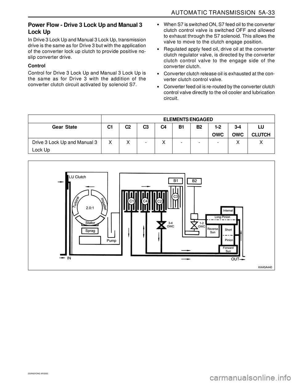
Power Flow - Drive 3 Lock Up and Manual 3
Lock Up
In Drive 3 Lock Up and Manual 3 Lock Up, transmission
drive is the same as for Drive 3 but with the application
of the converter lock up clutch to provide positive no-
slip converter drive.
Control
Control for Drive 3 Lock Up and Manual 3 Lock Up is
the same as for Drive 3 with the addition of the
converter clutch circuit activated by solenoid S7.
When S7 is switched ON, S7 feed oil to the converter
clutch control valve is switched OFF and allowed
to exhaust through the S7 solenoid. This allows the
valve to move to the clutch engage position.
Regulated apply feed oil, drive oil at the converter
clutch regulator valve, is directed by the converter
clutch control valve to the engage side of the
converter clutch.
Converter clutch release oil is exhausted at the con-
verter clutch control valve.
Converter feed oil is re-routed by the converter clutch
control valve directly to the oil cooler and lubrication
circuit.
Gear State
Drive 3 Lock Up and Manual 3
Lock UpC1
X
C2
XC3
-C4
XB1
-B2
-1-2
OWC
-3-4
OWC
XLU
CLUTCH
X ELEMENTS ENGAGED
KAA5A440
Page 1129 of 2053

AUTOMATIC TRANSMISSION 5A-35
SSANGYONG MY2002
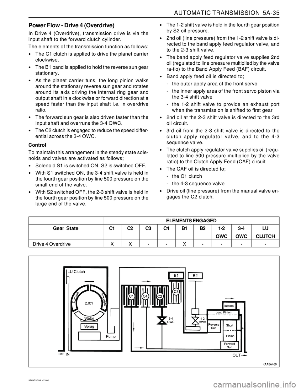
Power Flow - Drive 4 (Overdrive)
In Drive 4 (Overdrive), transmission drive is via the
input shaft to the forward clutch cylinder.
The elements of the transmission function as follows;
The C1 clutch is applied to drive the planet carrier
clockwise.
The B1 band is applied to hold the reverse sun gear
stationary.
As the planet carrier tuns, the long pinion walks
around the stationary reverse sun gear and rotates
around its axis driving the internal ring gear and
output shaft in a clockwise or forward direction at a
speed faster than the input shaft i.e. in overdrive
ratio.
The forward sun gear is also driven faster than the
input shaft and overruns the 3-4 OWC.
The C2 clutch is engaged to reduce the speed differ-
ential across the 3-4 OWC.
Control
To maintain this arrangement in the steady state sole-
noids and valves are activated as follows;
Solenoid S1 is switched ON. S2 is switched OFF.
With S1 switched ON, the 3-4 shift valve is held in
the fourth gear position by line 500 pressure on the
small end of the valve.
With S2 switched OFF, the 2-3 shift valve is held in
the fourth gear position by line 500 pressure on the
large end of the valve.
The 1-2 shift valve is held in the fourth gear position
by S2 oil pressure.
2nd oil (line pressure) from the 1-2 shift valve is di-
rected to the band apply feed regulator valve, and
to the 2-3 shift valve.
The band apply feed regulator valve supplies 2nd
oil (regulated to line pressure multiplied by the valve
ra-tio) to the Band Apply Feed (BAF) circuit.
Band apply feed oil is directed to;
- the outer apply area of the front servo
- the inner apply area of the front servo piston via
the 3-4 shift valve
- the 1-2 shift valve to provide an exhaust port
when the transmission is shifted to first gear
2nd oil at the 2-3 shift valve is directed to the 3rd
oil circuit.
3rd oil from the 2-3 shift valve is directed to the
clutch apply regulator valve, and to the 4-3
sequence valve.
The clutch apply regulator valve supplies oil (regu-
lated to line 500 pressure multiplied by the valve
ratio) to the Clutch Apply Feed (CAF) circuit.
The CAF oil is directed to;
- the C1 clutch
- the 4-3 sequence valve
Drive oil (line pressure) from the manual valve en-
gages the C2 clutch.
Gear State
Drive 4 Overdrive
C1
XC2
XC3
-C4
-B1
XB2
-1-2
OWC
-3-4
OWC
-LU
CLUTCH
- ELEMENTS ENGAGED
KAA5A460
Page 1130 of 2053
5A-36 AUTOMATIC TRANSMISSION
SSANGYONG MY2002
DRIVE 4 LOCK UP
KAA5A47A
Page 1131 of 2053

AUTOMATIC TRANSMISSION 5A-37
SSANGYONG MY2002
Power Flow - Drive 4 Lock Up
In Drive 4 Lock Up, transmission drive is the same as
for Drive 4 but with the application of the converter
lock up clutch to provide positive no-slip converter
drive.
Control
To maintain this arrangement in the steady state sole-
noids and valves are activated as follows;
When S7 is switched ON, S7 feed oil to the converter
clutch control valve is switched OFF and allowed
to exhaust through the S7 solenoid. This allows the
valve to move to the clutch engage position.
Regulated apply feed oil, drived from drive oil at
the converter clutch regulator valve, is directed by
the converter clutch control valve to the engage side
of the converter clutch.
Converter clutch release oil is exhausted at the con-
verter clutch control valve.
Converter feed oil is re-routed by the converter clutch
control valve directly to the oil cooler and lubrication
circuit.
C1
XC2
XC3
-C4
-B1
XB2
-1-2
OWC
-3-4
OWC
-LU
CLUTCH
- ELEMENTS ENGAGED
Gear State
Drive 4 Lock Up
KAA5A480
Page 1136 of 2053

AUTOMATIC TRANSMISSION 5A-41
SSANGYONG MY2002
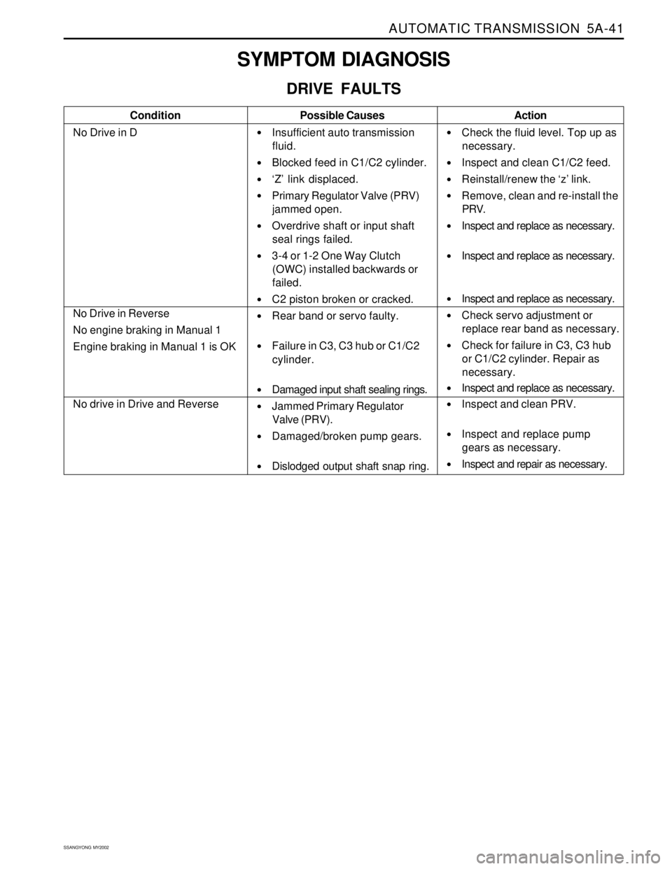
SYMPTOM DIAGNOSIS
DRIVE FAULTS
Condition
No Drive in DPossible Causes
Insufficient auto transmission
fluid.
Blocked feed in C1/C2 cylinder.
‘Z’ link displaced.
Primary Regulator Valve (PRV)
jammed open.
Overdrive shaft or input shaft
seal rings failed.
3-4 or 1-2 One Way Clutch
(OWC) installed backwards or
failed.
C2 piston broken or cracked.
Rear band or servo faulty.
Failure in C3, C3 hub or C1/C2
cylinder.
Damaged input shaft sealing rings.
Jammed Primary Regulator
Valve (PRV).
Damaged/broken pump gears.
Dislodged output shaft snap ring.Action
Check the fluid level. Top up as
necessary.
Inspect and clean C1/C2 feed.
Reinstall/renew the ‘z’ link.
Remove, clean and re-install the
PRV.
Inspect and replace as necessary.
Inspect and replace as necessary.
Inspect and replace as necessary.
Check servo adjustment or
replace rear band as necessary.
Check for failure in C3, C3 hub
or C1/C2 cylinder. Repair as
necessary.
Inspect and replace as necessary.
Inspect and clean PRV.
Inspect and replace pump
gears as necessary.
Inspect and repair as necessary.
No Drive in Reverse
No engine braking in Manual 1
Engine braking in Manual 1 is OK
No drive in Drive and Reverse
Page 1142 of 2053
AUTOMATIC TRANSMISSION 5A-47
SSANGYONG MY2002
Condition
Firm converter lock or unlockPossible Causes
Input shaft 'O' ring missing or
damaged.
Converter clutch regulator valve
in backwards.
Input shaft 'O' ring missing or
damaged.
C1 bias valve in backwards.Action
Inspect and replace the 'O' ring
as necessary.
Inspect and refit the valve as
necessary.
Inspect and replace the 'O' ring
as necessary.
Inspect and refit the valve as
necessary.
No lock up at light throttle
Page 1147 of 2053

5A-52 AUTOMATIC TRANSMISSION
SSANGYONG MY2002
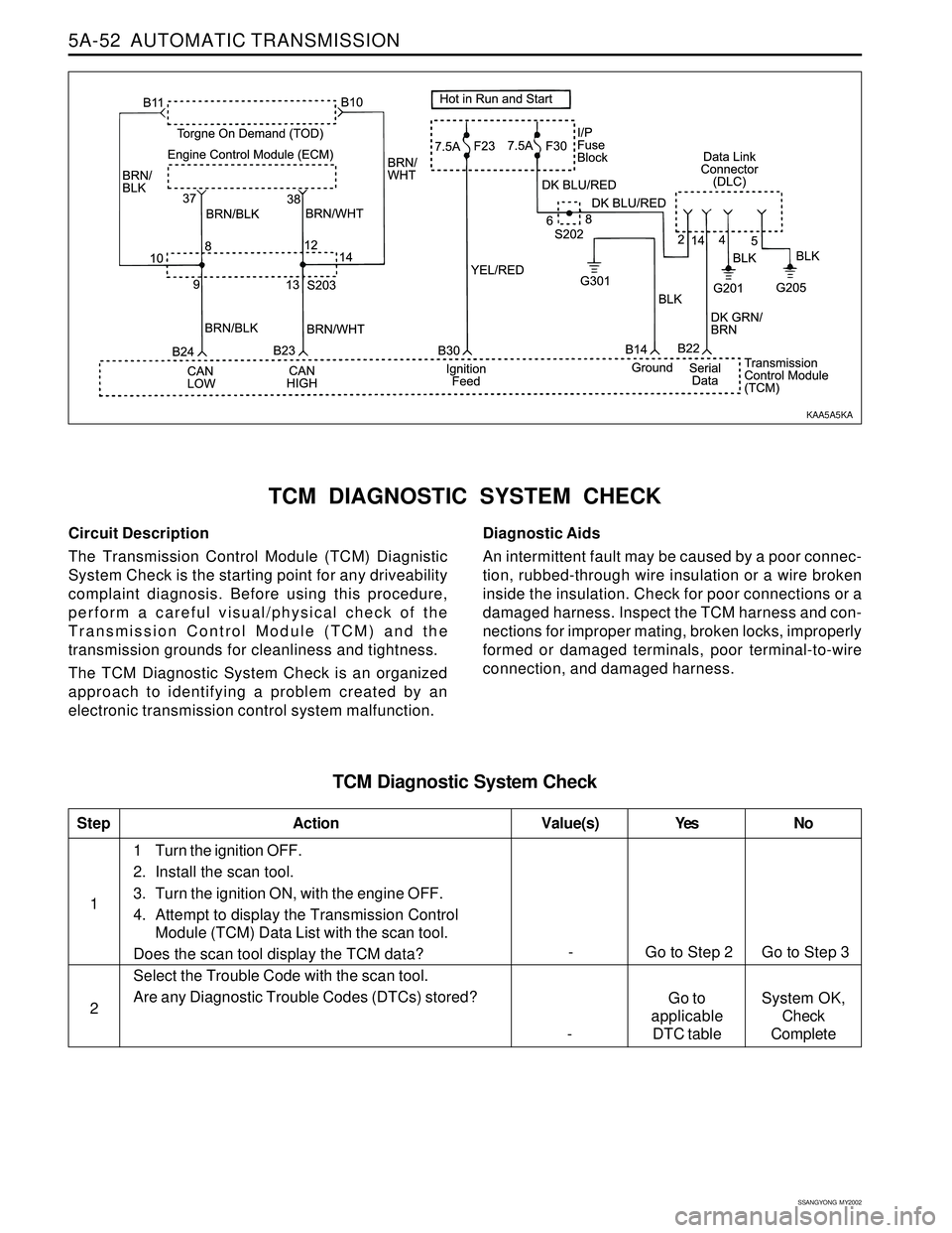
Circuit Description
The Transmission Control Module (TCM) Diagnistic
System Check is the starting point for any driveability
complaint diagnosis. Before using this procedure,
perform a careful visual/physical check of the
Transmission Control Module (TCM) and the
transmission grounds for cleanliness and tightness.
The TCM Diagnostic System Check is an organized
approach to identifying a problem created by an
electronic transmission control system malfunction.
TCM DIAGNOSTIC SYSTEM CHECK
Diagnostic Aids
An intermittent fault may be caused by a poor connec-
tion, rubbed-through wire insulation or a wire broken
inside the insulation. Check for poor connections or a
damaged harness. Inspect the TCM harness and con-
nections for improper mating, broken locks, improperly
formed or damaged terminals, poor terminal-to-wire
connection, and damaged harness.
TCM Diagnostic System Check
1
StepAction Value(s) Yes No
21 Turn the ignition OFF.
2. Install the scan tool.
3. Turn the ignition ON, with the engine OFF.
4. Attempt to display the Transmission Control
Module (TCM) Data List with the scan tool.
Does the scan tool display the TCM data?
Select the Trouble Code with the scan tool.
Are any Diagnostic Trouble Codes (DTCs) stored?
- Go to Step 2 Go to Step 3
Go to
applicable
DTC table -System OK,
Check
Complete
KAA5A5KA