Page 391 of 2053

M161 ENGINE MECHANICAL 1B2 -- 103
D AEW OO M Y_2000
Group Code Letter of CylinderGroup Code Letter 1)Cylinder Bore Size (mm)
Standard SizeAφ89.900 --φ89.906
E20 :φ89.9
E23φ909Xφ89.906 --φ89.912E23 :φ90.9Bφ89.912 --φ89.918
1st Repair Size
(StddSi025)
Aφ90.150 --φ90.156p
(Standard Size + 0.25)Xφ89.156 --φ90.162
Bφ90.162 --φ90.168
2nd Repair Size
(StddSi05)
Aφ90.400 --φ90.406p
(Standard Size + 0.5)Xφ90.406 --φ90.412
Bφ90.412 --φ90.418
1) The group code letters are carved on the surface of the piston crown and in the mating surface of the crankcase.
ServiceDataStandard
Wear Limit in Longitudinal and Transverse Direction0.1 mm
Permissible Deviation of Cylinder Out -- of -- roundWhen new0.007 mmy
Wear limit0.05 mm
Permissible Deviation of Rectangular Cylinder Height (Except Chamfered Area)0.05 mm
Basic Peak -- to-- valley Height After Final Honing and Brushing0.003 -- 0.006 mm
Chamfer Angle75°
Honing Angle50°±10°
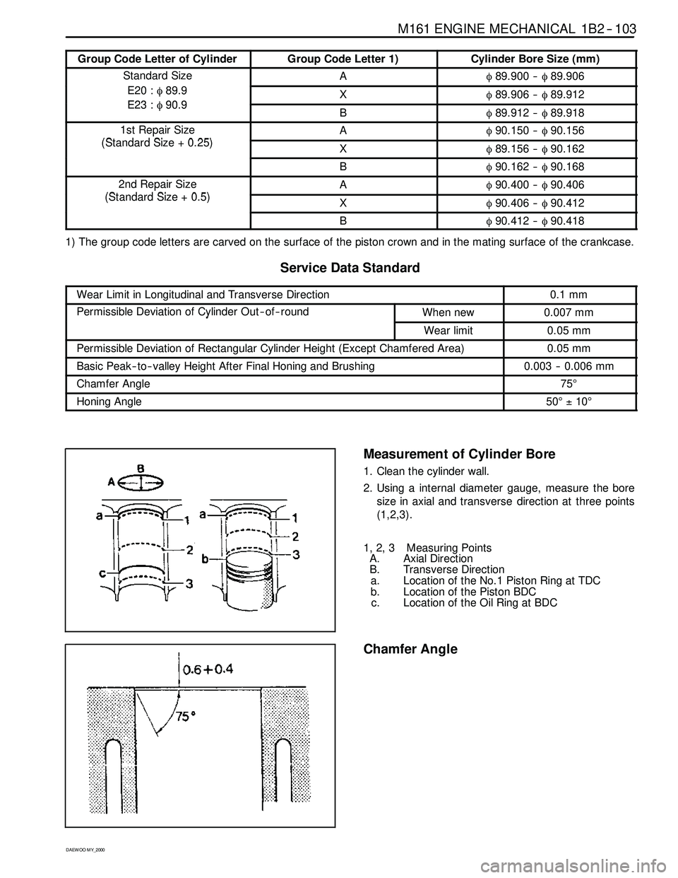
Measurement of Cylinder Bore
1. Clean the cylinder wall.
2. Using a internal diameter gauge, measure the bore
size in axial and transverse direction at three points
(1,2,3).
1, 2, 3 Measuring Points
A. Axial Direction
B. Transverse Direction
a. Location of the No.1 Piston Ring at TDC
b. Location of the Piston BDC
c. Location of the Oil Ring at BDC
Chamfer Angle
Page 397 of 2053

1D2 -- 2 M161 ENGINE COOLING
D AEW OO M Y_2000
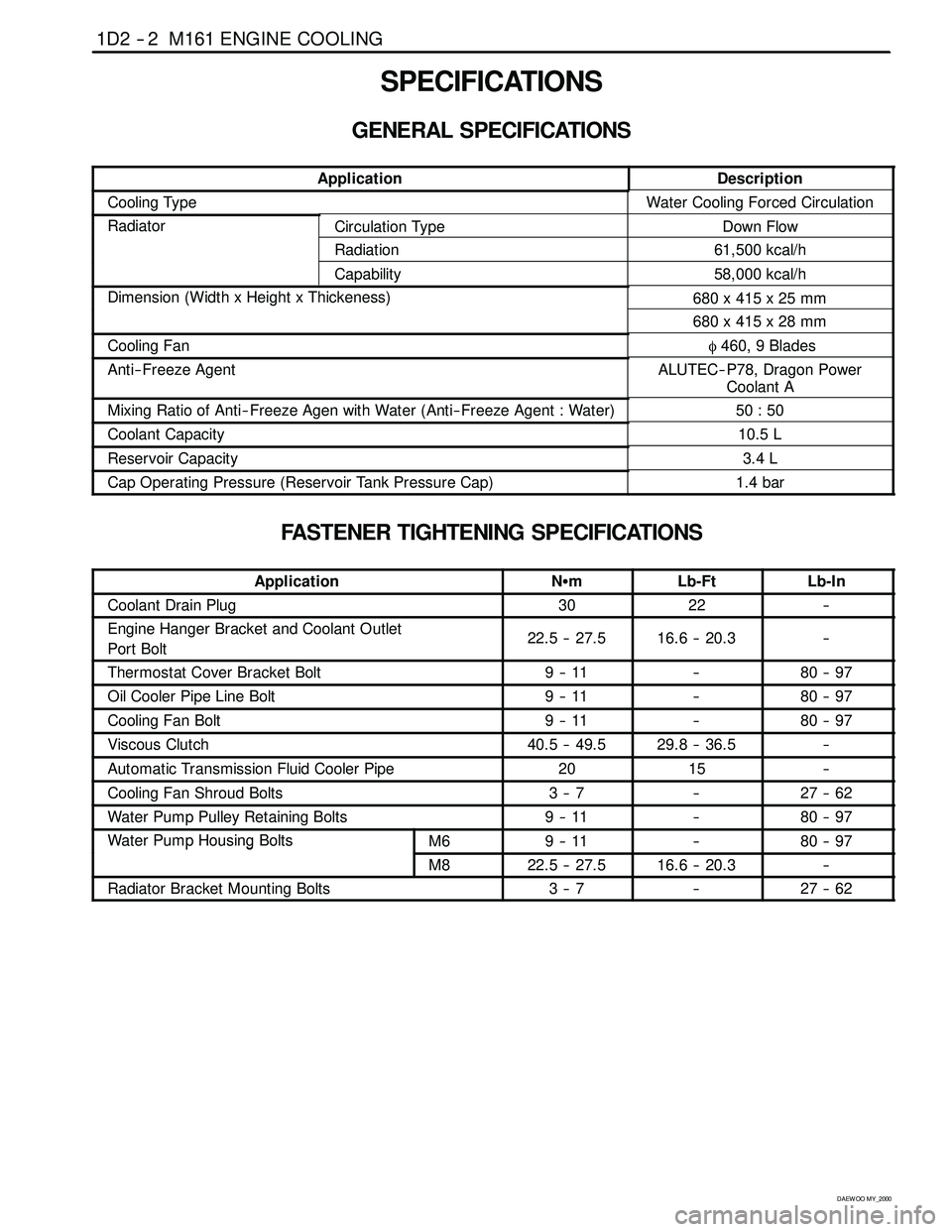
SPECIFICATIONS
GENERAL SPECIFICATIONS
ApplicationDescription
Cooling TypeWater Cooling Forced Circulation
RadiatorCirculation TypeDown Flow
Radiation61,500 kcal/h
Capability58,000 kcal/h
Dimension (Width x Height x Thickeness)680 x 415 x 25 mm(g)
680 x 415 x 28 mm
Cooling Fanφ460, 9 Blades
Anti-- Freeze AgentALUTEC-- P78, Dragon Power
Coolant A
Mixing Ratio of Anti-- Freeze Agen with Water (Anti-- Freeze Agent : Water)50 : 50
Coolant Capacity10.5 L
Reservoir Capacity3.4 L
Cap Operating Pressure (Reservoir Tank Pressure Cap)1.4 bar
FASTENER TIGHTENING SPECIFICATIONS
ApplicationNSmLb-FtLb-In
Coolant Drain Plug3022--
Engine Hanger Bracket and Coolant Outlet
Port Bolt22.5 -- 27.516.6 -- 20.3--
Thermostat Cover Bracket Bolt9--11--80 -- 97
Oil Cooler Pipe Line Bolt9--11--80 -- 97
Cooling Fan Bolt9--11--80 -- 97
Viscous Clutch40.5 -- 49.529.8 -- 36.5--
Automatic Transmission Fluid Cooler Pipe2015--
Cooling Fan Shroud Bolts3--7--27 -- 62
Water Pump Pulley Retaining Bolts9--11--80 -- 97
Water Pump Housing BoltsM69--11--80 -- 97pg
M822.5 -- 27.516.6 -- 20.3--
Radiator Bracket Mounting Bolts3--7--27 -- 62
Page 410 of 2053
M161 ENGINE COOLING 1D2 -- 15
D AEW OO M Y_2000
REMOVAL AND INSTALLATION OF RADIATOR
Preceding Work: Removal of cooling fan shroud
1 Inlet Hose
2 Hose (to Engine)
3 Hose (to 3-- way Connector)
4 Make-- up Hose (to Coolant Reservoir)
5 3-- way Connector
6 Automatic Transmission Oil Cooling Hose
(A/T Equippend Vehicle)7 Bolt (M6 X 20, 4 pieces)
3--7 NSm (27-- 62 lb-in) .....................
8 Insulator
9 Radiator Bracket
10 Radiator
Page 417 of 2053
1E 2 -- 6 M161 ENGINE ELECTRICAL
D AEW OO M Y_2000
SPARK PLUG
Preceding Work: Removal of intake air duct
1 Screw (3 pieces) 9-- 11 NSm (80-- 97 lb-in) ......
2 Adaptor (3 pieces)
3 Ignition Coil Cable Cover
4 Spark Plug Connector
5 Ignition Coil Connector6 Bolts (M6 X 25, 4 pieces)
9--11 NSm (80-- 97 lb-in) .....................
7 Ignition Coil (T1/1)
8 Coupling Plug
9 Spark Plug 20-- 30 NSm (15-- 22 lb-ft) ..........
10 Ignition Coil (T1/2)
Page 418 of 2053
M161 ENGINE ELECTRICAL 1E 2 -- 7
D AEW OO M Y_2000
Replacement Procedure
1. Unscrew the three screws(1) and remove the spark
plug cable cover.
Installation Notice
Tightening Torque
9--11NSm (80 -- 97 lb-in)
2. Disconnect the cable from ignition coil and spark
plug.
3. Unscrew two bolts(M6 X 25) from each ignition coil
and remove the ignition coil(arrow).
Installation Notice
Tightening Torque
9--11NSm (80 -- 97 lb-in)
4. Remove the spark plug .
Installation Notice
Tightening Torque
20 -- 30 NSm (15 -- 22 lb-ft)
Clearance0.8+0.1mm
Notice:
DTighten the spark plug with specified torque.
DInstall the ignition coil to number 2 and 4 cylinder, and
connect the cable to number 1, 4 and 2, 3 cylinder.
-- T1/1 : cylinder 1 and 4
-- T1/2 : cylinder 2 and 3
Page 419 of 2053
1E 2 -- 8 M161 ENGINE ELECTRICAL
D AEW OO M Y_2000
IGNITION CABLE
Preceding Work: Removal of intake air duct
1 Control Cable Connection
2 Ignition Cable
3 Spark Plug Connector
4 Coupling Plug5a, 5b Secondary Voltage Connection
EIronCore
L1 Secondary Ignition Coil
L2 Primary Ignition Coil
Page 420 of 2053

M161 ENGINE ELECTRICAL 1E 2 -- 9
D AEW OO M Y_2000
Removal & Installation Procedure
1. Disconnect the battery negative cable.
2. Unscrew the 3 screws and remove the ignition cable
duct cover.
Installation Notice
Tightening Torque
9--11NSm (80 -- 97 lb-in)
3. Seperate the cable from the ignition cable and the
spark plug.
4. Remove the 2 bolts from each ignition cable and re-
move the ignition cables.
Installation Notice
Tightening Torque
9--11NSm (80 -- 97 lb-in)
Install the ignition cable to the cylinder 2 and 4 and
connect the cable from 1 to 4, and from 2 to 3.
-- T1/1 : Cylinder 1 and 4
-- T1/2 : Cylinder 2 and 3
5. Installation should follow the removal procedure in
the reverse order.
Ignition Cable and Cable Lay- out
1. Firing Order : 1 -- 3 -- 4 -- 2
2. T1/1 : Connect the cylinder 1 + 4
3. T1/2 : Connect the cylinder 2 + 3
Inspection & Maintenance (for E2.3 MSE)
1. Measure the primary resistance between the cable
terminals 1 and 15 after removing the ignition cable
wiring connector (1 and 15) with ignition switch OFF.
Notice:Replace the ignition coil if out of the specified
resistance.
Specified Value
0.9 -- 1.6Ω
2. Measure the primary voltage(T1/1) between the ECU
terminals No.72 and No.69 during the engine crank-
ing (starter motor activated).
Specified Value
200 -- 350 v
Page 421 of 2053
1E 2 -- 10 M161 ENGINE ELECTRICAL
D AEW OO M Y_2000
DT1/2 : between No.71 and No.69
Notice:Check the ignition cable and the ECU if out of
the specified value.
3. Measure the secondary cable resistance between the
ignition coil 5a and 5b using a multimeter.
Specified Value
6--8.5kΩ