1997 SSANGYONG KORANDO wiring
[x] Cancel search: wiringPage 1172 of 2053
AUTOMATIC TRANSMISSION 5A-77
SSANGYONG MY2002
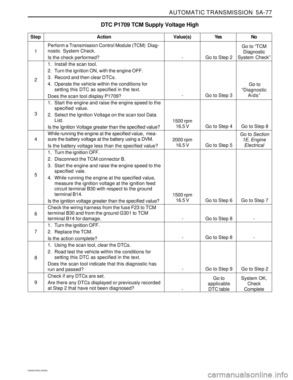
DTC P1709 TCM Supply Voltage High
1Perform a Transmission Control Module (TCM) Diag-
nostic System Check.
Is the check performed?
1. Install the scan tool.
2. Turn the ignition ON, with the engine OFF.
3. Record and then clear DTCs.
4. Operate the vehicle within the conditions for
setting this DTC as specified in the text.
Does the scan tool display P1709?
1. Start the engine and raise the engine speed to the
specified value.
2. Select the Ignition Voltage on the scan tool Data
List.
Is the Ignition Voltage greater than the specified value?
While running the engine at the specified value, mea-
sure the battery voltage at the battery using a DVM.
Is the battery voltage less than the specified value?
1. Turn the ignition OFF.
2. Disconnect the TCM connector B.
3. Start the engine and raise the engine speed to the
specified vale.
4. While running the engine at the specified value,
measure the ignition voltage at the ignition feed
circuit terminal B30 with respect to the ground
terminal B14.
Is the ignition voltage greater than the specified value?
Check the wiring harness from the fuse F23 to TCM
terminal B30 and from the ground G301 to TCM
terminal B14 for damage.
1. Turn the ignition OFF.
2. Replace the TCM.
Is the action complete?
1. Using the scan tool, clear the DTCs.
2. Road test the vehicle within the conditions for
setting this DTC as specified in the text.
Does the scan tool indicate that this diagnostic has
run and passed?
Check if any DTCs are set.
Are there any DTCs displayed or previously recorded
at Step 2 that have not been diagnosed?
StepAction Value(s) Yes No
2
3
5
6 4
- Go to Step 8 -
7
- Go to Step 8 -
8
- Go to Step 9 Go to Step 2
9
- Go to Step 2Go to “TCM
Diagnostic
System Check”
- Go to Step 3 Go to
“Diagnostic
Aids”
1500 rpm
16.5 V
Go to Step 6 Go to Step 7
1500 rpm
16.5 V Go to Step 4 Go to Step 8
2000 rpm
16.5 V Go to Step 5 Go to Section
1E, Engine
Electrical
-Go to
applicable
DTC tableSystem OK,
Check
Complete
Page 1173 of 2053
5A-78 AUTOMATIC TRANSMISSION
SSANGYONG MY2002
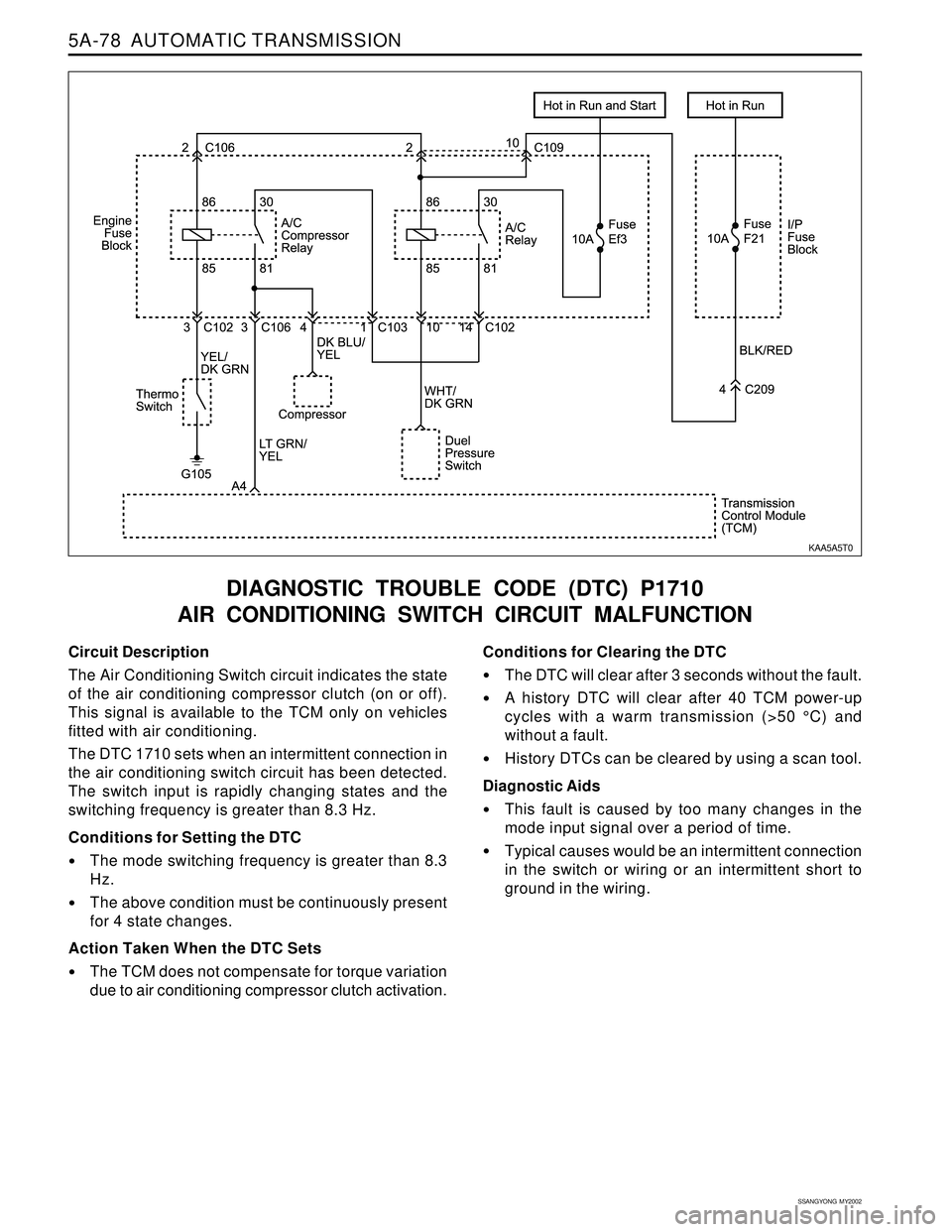
Circuit Description
The Air Conditioning Switch circuit indicates the state
of the air conditioning compressor clutch (on or off).
This signal is available to the TCM only on vehicles
fitted with air conditioning.
The DTC 1710 sets when an intermittent connection in
the air conditioning switch circuit has been detected.
The switch input is rapidly changing states and the
switching frequency is greater than 8.3 Hz.
Conditions for Setting the DTC
The mode switching frequency is greater than 8.3
Hz.
The above condition must be continuously present
for 4 state changes.
Action Taken When the DTC Sets
The TCM does not compensate for torque variation
due to air conditioning compressor clutch activation.
DIAGNOSTIC TROUBLE CODE (DTC) P1710
AIR CONDITIONING SWITCH CIRCUIT MALFUNCTION
Conditions for Clearing the DTC
The DTC will clear after 3 seconds without the fault.
A history DTC will clear after 40 TCM power-up
cycles with a warm transmission (>50 °C) and
without a fault.
History DTCs can be cleared by using a scan tool.
Diagnostic Aids
This fault is caused by too many changes in the
mode input signal over a period of time.
Typical causes would be an intermittent connection
in the switch or wiring or an intermittent short to
ground in the wiring.
KAA5A5T0
Page 1177 of 2053
5A-82 AUTOMATIC TRANSMISSION
SSANGYONG MY2002
Circuit Description
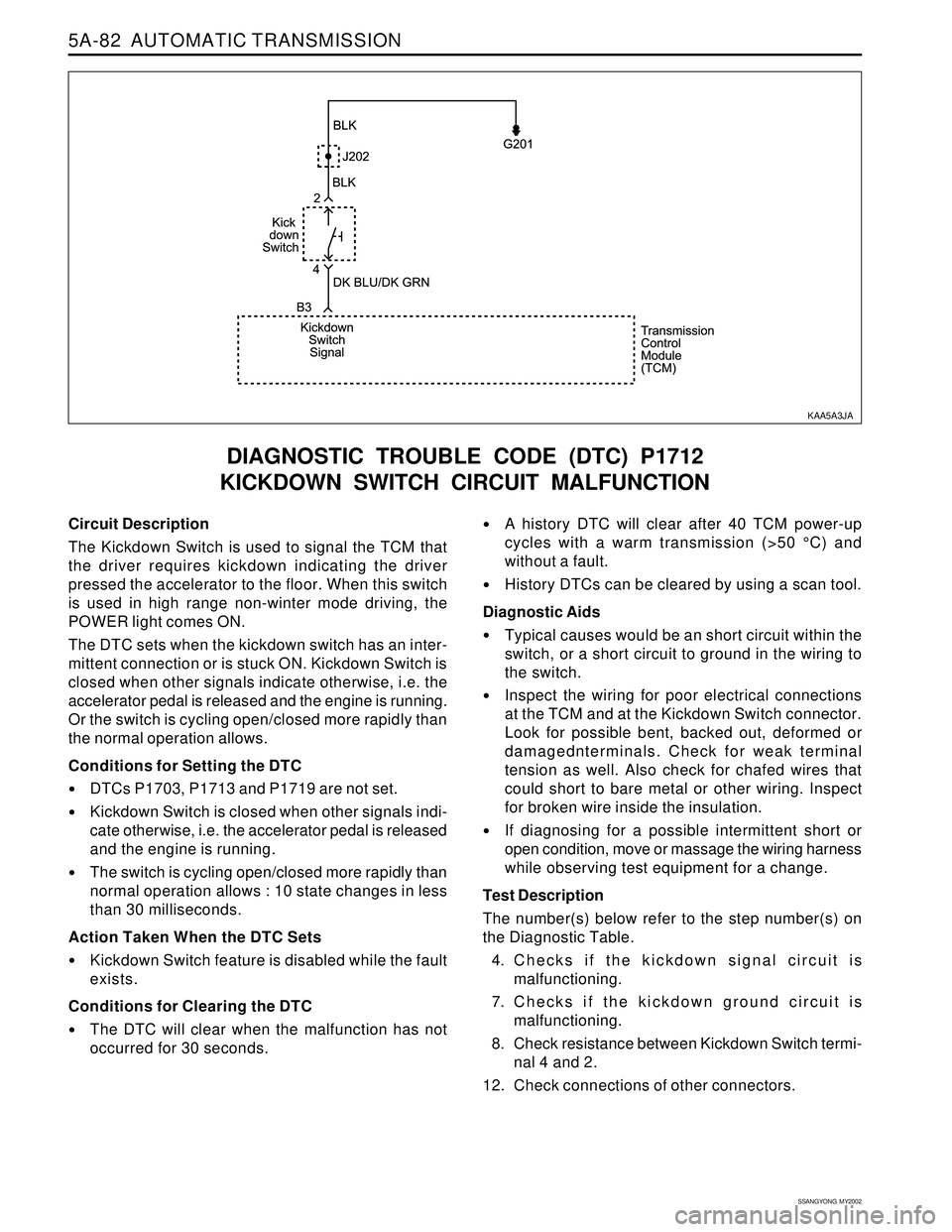
The Kickdown Switch is used to signal the TCM that
the driver requires kickdown indicating the driver
pressed the accelerator to the floor. When this switch
is used in high range non-winter mode driving, the
POWER light comes ON.
The DTC sets when the kickdown switch has an inter-
mittent connection or is stuck ON. Kickdown Switch is
closed when other signals indicate otherwise, i.e. the
accelerator pedal is released and the engine is running.
Or the switch is cycling open/closed more rapidly than
the normal operation allows.
Conditions for Setting the DTC
DTCs P1703, P1713 and P1719 are not set.
Kickdown Switch is closed when other signals indi-
cate otherwise, i.e. the accelerator pedal is released
and the engine is running.
The switch is cycling open/closed more rapidly than
normal operation allows : 10 state changes in less
than 30 milliseconds.
Action Taken When the DTC Sets
Kickdown Switch feature is disabled while the fault
exists.
Conditions for Clearing the DTC
The DTC will clear when the malfunction has not
occurred for 30 seconds.
DIAGNOSTIC TROUBLE CODE (DTC) P1712
KICKDOWN SWITCH CIRCUIT MALFUNCTION
A history DTC will clear after 40 TCM power-up
cycles with a warm transmission (>50 °C) and
without a fault.
History DTCs can be cleared by using a scan tool.
Diagnostic Aids
Typical causes would be an short circuit within the
switch, or a short circuit to ground in the wiring to
the switch.
Inspect the wiring for poor electrical connections
at the TCM and at the Kickdown Switch connector.
Look for possible bent, backed out, deformed or
damagednterminals. Check for weak terminal
tension as well. Also check for chafed wires that
could short to bare metal or other wiring. Inspect
for broken wire inside the insulation.
If diagnosing for a possible intermittent short or
open condition, move or massage the wiring harness
while observing test equipment for a change.
Test Description
The number(s) below refer to the step number(s) on
the Diagnostic Table.
4. Checks if the kickdown signal circuit is
malfunctioning.
7. Checks if the kickdown ground circuit is
malfunctioning.
8. Check resistance between Kickdown Switch termi-
nal 4 and 2.
12. Check connections of other connectors.
KAA5A3JA
Page 1181 of 2053
5A-86 AUTOMATIC TRANSMISSION
SSANGYONG MY2002
Circuit Description
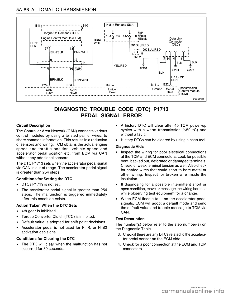
The Controller Area Network (CAN) connects various
control modules by using a twisted pair of wires, to
share common information. This results in a reduction
of sensors and wiring. TCM obtains the actual engine
speed and throttle position, vehicle speed and
accelerator pedal position etc. from ECM via CAN
without any additional sensors.
The DTC P1713 sets when the accelerator pedal signal
via CAN is out of range. The accelerator pedal signal
is greater than 254 steps.
Conditions for Setting the DTC
DTCs P1719 is not set.
The accelerator pedal signal is greater than 254
steps. The malfunction is triggered immediately
after this condition exists.
Action Taken When the DTC Sets
4th gear is inhibited.
Torque Converter Clutch (TCC) is inhibited.
Default value is adopted for shift point decisions.
Accelerator pedal is not used for P, R, or N B2
activation decisions.
Conditions for Clearing the DTC
The DTC will clear when the malfunction has not
occurred for 30 seconds.
DIAGNOSTIC TROUBLE CODE (DTC) P1713
PEDAL SIGNAL ERROR
A history DTC will clear after 40 TCM power-up
cycles with a warm transmission (>50 °C) and
without a fault.
History DTCs can be cleared by using a scan tool.
Diagnostic Aids
Inspect the wiring for poor electrical connections
at the TCM and ECM connectors. Look for possible
bent, backed out, deformed or damaged terminals.
Check for weak terminal tension as well. Also check
for chafed wires that could short to bare metal or
other wiring. Inspect for broken wire inside the
insulation.
If diagnosing for a possible intermittent short or
open condition, move or massage the wiring harness
while observing test equipment for a change.
When ECM finds a fault on the accelerator pedal
signals, ECM will adopt a default mode and send
the default value and trouble message to TCM via
CAN.
Test Description
The number(s) below refer to the step number(s) on
the Diagnostic Table.
3. Check if there are any DTCs related to the accelera-
tor pedal sensor on the ECM side.
4. Check for a poor connection at the ECM and TCM
connectors.
KAA5A5KA
Page 1185 of 2053
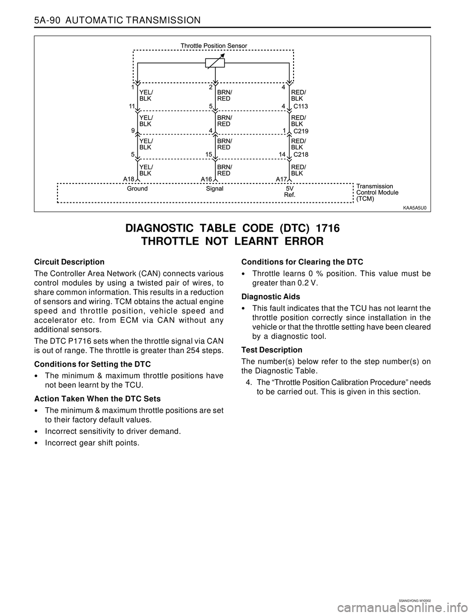
5A-90 AUTOMATIC TRANSMISSION
SSANGYONG MY2002
Circuit Description
The Controller Area Network (CAN) connects various
control modules by using a twisted pair of wires, to
share common information. This results in a reduction
of sensors and wiring. TCM obtains the actual engine
speed and throttle position, vehicle speed and
accelerator etc. from ECM via CAN without any
additional sensors.
The DTC P1716 sets when the throttle signal via CAN
is out of range. The throttle is greater than 254 steps.
Conditions for Setting the DTC
The minimum & maximum throttle positions have
not been learnt by the TCU.
Action Taken When the DTC Sets
The minimum & maximum throttle positions are set
to their factory default values.
Incorrect sensitivity to driver demand.
Incorrect gear shift points.
DIAGNOSTIC TABLE CODE (DTC) 1716
THROTTLE NOT LEARNT ERROR
Conditions for Clearing the DTC
Throttle learns 0 % position. This value must be
greater than 0.2 V.
Diagnostic Aids
This fault indicates that the TCU has not learnt the
throttle position correctly since installation in the
vehicle or that the throttle setting have been cleared
by a diagnostic tool.
Test Description
The number(s) below refer to the step number(s) on
the Diagnostic Table.
4. The “Throttle Position Calibration Procedure” needs
to be carried out. This is given in this section.
KAA5A5U0
Page 1189 of 2053
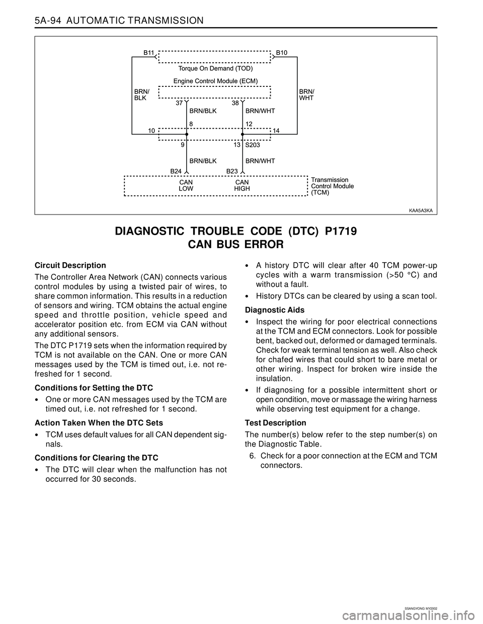
5A-94 AUTOMATIC TRANSMISSION
SSANGYONG MY2002
Circuit Description
The Controller Area Network (CAN) connects various
control modules by using a twisted pair of wires, to
share common information. This results in a reduction
of sensors and wiring. TCM obtains the actual engine
speed and throttle position, vehicle speed and
accelerator position etc. from ECM via CAN without
any additional sensors.
The DTC P1719 sets when the information required by
TCM is not available on the CAN. One or more CAN
messages used by the TCM is timed out, i.e. not re-
freshed for 1 second.
Conditions for Setting the DTC
One or more CAN messages used by the TCM are
timed out, i.e. not refreshed for 1 second.
Action Taken When the DTC Sets
TCM uses default values for all CAN dependent sig-
nals.
Conditions for Clearing the DTC
The DTC will clear when the malfunction has not
occurred for 30 seconds.
DIAGNOSTIC TROUBLE CODE (DTC) P1719
CAN BUS ERROR
A history DTC will clear after 40 TCM power-up
cycles with a warm transmission (>50 °C) and
without a fault.
History DTCs can be cleared by using a scan tool.
Diagnostic Aids
Inspect the wiring for poor electrical connections
at the TCM and ECM connectors. Look for possible
bent, backed out, deformed or damaged terminals.
Check for weak terminal tension as well. Also check
for chafed wires that could short to bare metal or
other wiring. Inspect for broken wire inside the
insulation.
If diagnosing for a possible intermittent short or
open condition, move or massage the wiring harness
while observing test equipment for a change.
Test Description
The number(s) below refer to the step number(s) on
the Diagnostic Table.
6. Check for a poor connection at the ECM and TCM
connectors.
KAA5A3KA
Page 1190 of 2053
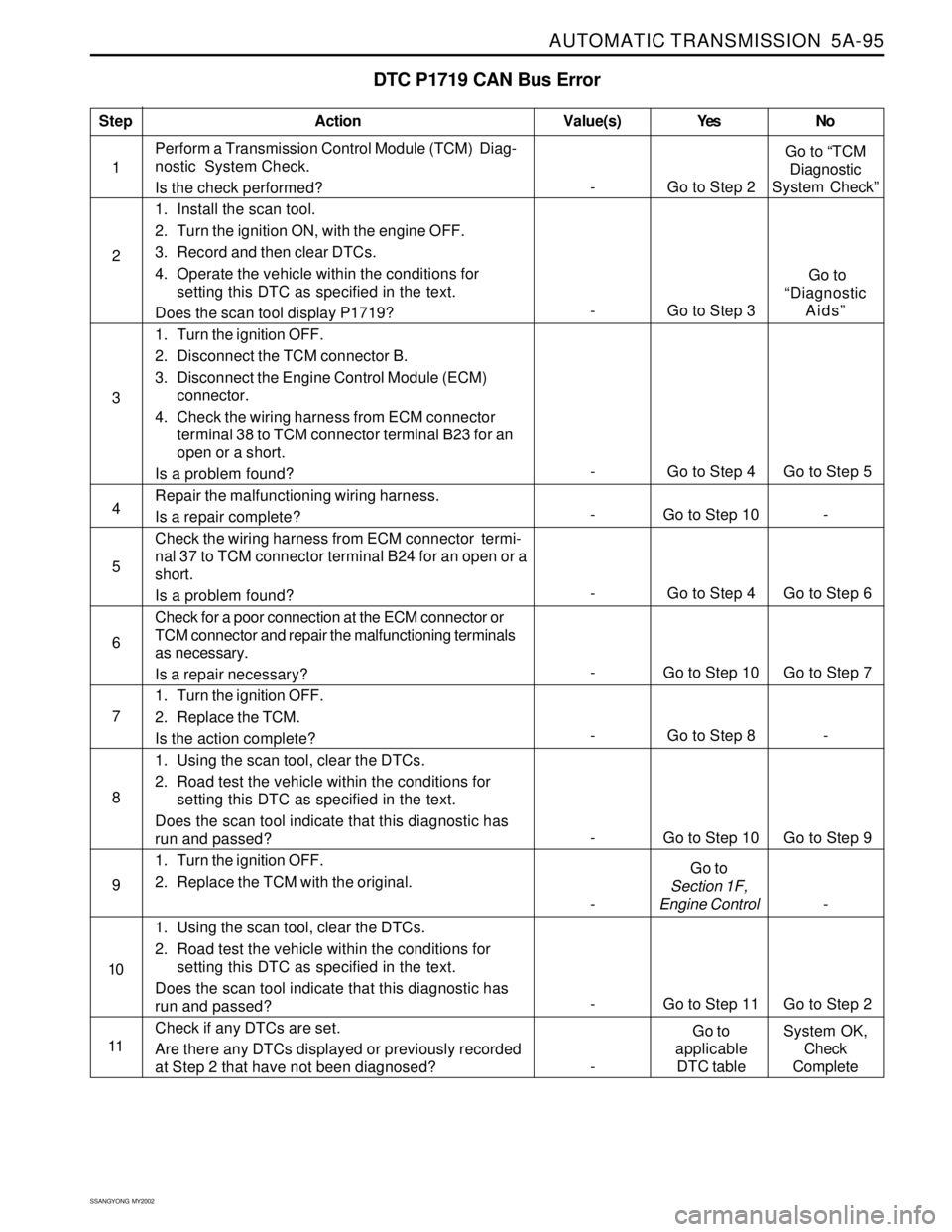
AUTOMATIC TRANSMISSION 5A-95
SSANGYONG MY2002
DTC P1719 CAN Bus Error
1Perform a Transmission Control Module (TCM) Diag-
nostic System Check.
Is the check performed?
1. Install the scan tool.
2. Turn the ignition ON, with the engine OFF.
3. Record and then clear DTCs.
4. Operate the vehicle within the conditions for
setting this DTC as specified in the text.
Does the scan tool display P1719?
1. Turn the ignition OFF.
2. Disconnect the TCM connector B.
3. Disconnect the Engine Control Module (ECM)
connector.
4. Check the wiring harness from ECM connector
terminal 38 to TCM connector terminal B23 for an
open or a short.
Is a problem found?
Repair the malfunctioning wiring harness.
Is a repair complete?
Check the wiring harness from ECM connector termi-
nal 37 to TCM connector terminal B24 for an open or a
short.
Is a problem found?
Check for a poor connection at the ECM connector or
TCM connector and repair the malfunctioning terminals
as necessary.
Is a repair necessary?
1. Turn the ignition OFF.
2. Replace the TCM.
Is the action complete?
1. Using the scan tool, clear the DTCs.
2. Road test the vehicle within the conditions for
setting this DTC as specified in the text.
Does the scan tool indicate that this diagnostic has
run and passed?
1. Turn the ignition OFF.
2. Replace the TCM with the original.
1. Using the scan tool, clear the DTCs.
2. Road test the vehicle within the conditions for
setting this DTC as specified in the text.
Does the scan tool indicate that this diagnostic has
run and passed?
Check if any DTCs are set.
Are there any DTCs displayed or previously recorded
at Step 2 that have not been diagnosed?
StepAction Value(s) Yes No
2
3
5
- Go to Step 8 - 6 4
- Go to Step 10 Go to Step 9 7
8
- Go to Step 11 Go to Step 2 9
10
- Go to Step 2Go to “TCM
Diagnostic
System Check”
-
Go to Step 4 Go to Step 5
- Go to Step 3 Go to
“Diagnostic
Aids”
11
-Go to
applicable
DTC tableSystem OK,
Check
Complete
- Go to Step 4 Go to Step 6
-Go to
Section 1F,
Engine Control-
- Go to Step 10 Go to Step 7
-
Go to Step 10-
Page 1193 of 2053
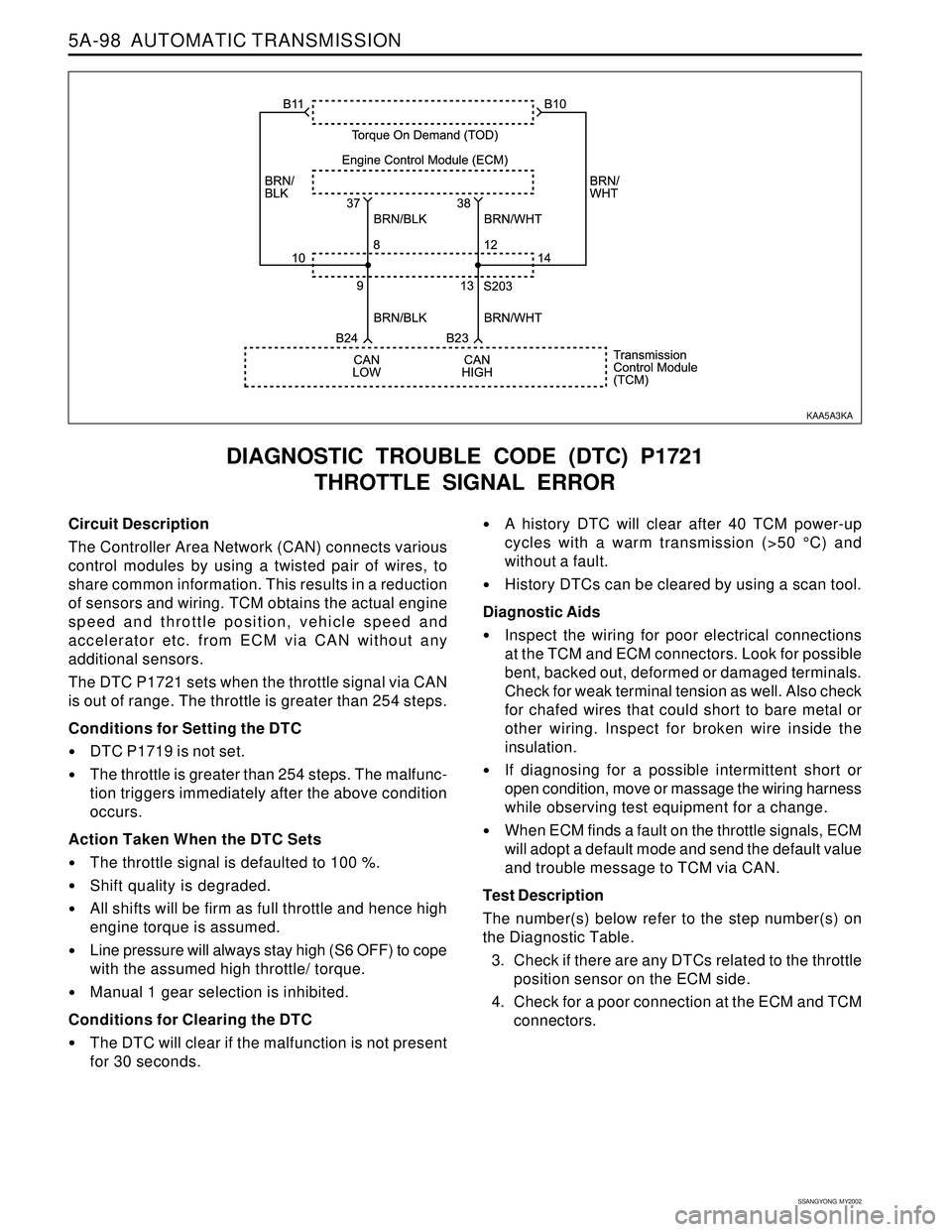
5A-98 AUTOMATIC TRANSMISSION
SSANGYONG MY2002
Circuit Description
The Controller Area Network (CAN) connects various
control modules by using a twisted pair of wires, to
share common information. This results in a reduction
of sensors and wiring. TCM obtains the actual engine
speed and throttle position, vehicle speed and
accelerator etc. from ECM via CAN without any
additional sensors.
The DTC P1721 sets when the throttle signal via CAN
is out of range. The throttle is greater than 254 steps.
Conditions for Setting the DTC
DTC P1719 is not set.
The throttle is greater than 254 steps. The malfunc-
tion triggers immediately after the above condition
occurs.
Action Taken When the DTC Sets
The throttle signal is defaulted to 100 %.
Shift quality is degraded.
All shifts will be firm as full throttle and hence high
engine torque is assumed.
Line pressure will always stay high (S6 OFF) to cope
with the assumed high throttle/ torque.
Manual 1 gear selection is inhibited.
Conditions for Clearing the DTC
The DTC will clear if the malfunction is not present
for 30 seconds.
DIAGNOSTIC TROUBLE CODE (DTC) P1721
THROTTLE SIGNAL ERROR
A history DTC will clear after 40 TCM power-up
cycles with a warm transmission (>50 °C) and
without a fault.
History DTCs can be cleared by using a scan tool.
Diagnostic Aids
Inspect the wiring for poor electrical connections
at the TCM and ECM connectors. Look for possible
bent, backed out, deformed or damaged terminals.
Check for weak terminal tension as well. Also check
for chafed wires that could short to bare metal or
other wiring. Inspect for broken wire inside the
insulation.
If diagnosing for a possible intermittent short or
open condition, move or massage the wiring harness
while observing test equipment for a change.
When ECM finds a fault on the throttle signals, ECM
will adopt a default mode and send the default value
and trouble message to TCM via CAN.
Test Description
The number(s) below refer to the step number(s) on
the Diagnostic Table.
3. Check if there are any DTCs related to the throttle
position sensor on the ECM side.
4. Check for a poor connection at the ECM and TCM
connectors.
KAA5A3KA