1997 SSANGYONG KORANDO wiring
[x] Cancel search: wiringPage 1083 of 2053
SSANGYONG MY2002
4F-100 ABS AND TCS
1
KAA4F330
KAA4F340
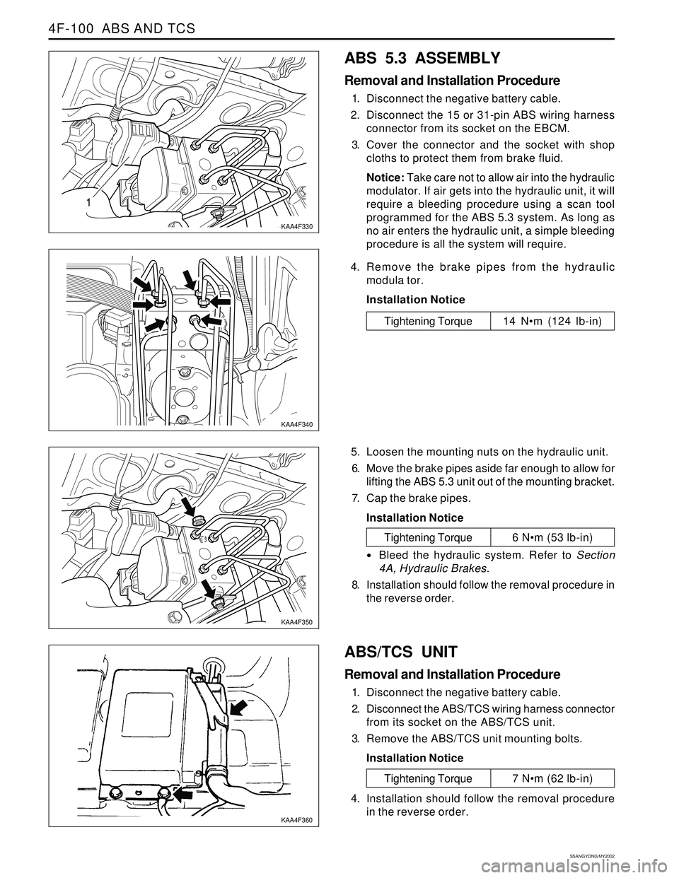
ABS 5.3 ASSEMBLY
Removal and Installation Procedure
1. Disconnect the negative battery cable.
2. Disconnect the 15 or 31-pin ABS wiring harness
connector from its socket on the EBCM.
3. Cover the connector and the socket with shop
cloths to protect them from brake fluid.
Notice: Take care not to allow air into the hydraulic
modulator. If air gets into the hydraulic unit, it will
require a bleeding procedure using a scan tool
programmed for the ABS 5.3 system. As long as
no air enters the hydraulic unit, a simple bleeding
procedure is all the system will require.
4. Remove the brake pipes from the hydraulic
modula tor.
Installation Notice
Tightening Torque 14 Nm (124 lb-in)
5. Loosen the mounting nuts on the hydraulic unit.
6. Move the brake pipes aside far enough to allow for
lifting the ABS 5.3 unit out of the mounting bracket.
7. Cap the brake pipes.
Installation Notice
ABS/TCS UNIT
Removal and Installation Procedure
1. Disconnect the negative battery cable.
2. Disconnect the ABS/TCS wiring harness connector
from its socket on the ABS/TCS unit.
3. Remove the ABS/TCS unit mounting bolts.
Installation Notice
KAA4F350
KAA4F360
Tightening Torque 6 Nm (53 lb-in)
Bleed the hydraulic system. Refer to Section
4A, Hydraulic Brakes.
8. Installation should follow the removal procedure in
the reverse order.
Tightening Torque 7 Nm (62 lb-in)
4. Installation should follow the removal procedure
in the reverse order.
Page 1095 of 2053
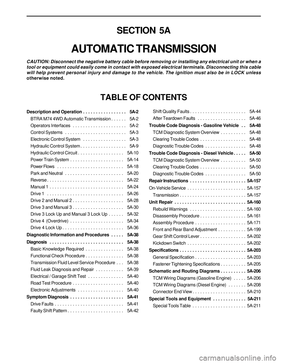
SECTION 5A
AUTOMATIC TRANSMISSION
CAUTION: Disconnect the negative battery cable before removing or installing any electrical unit or when a
tool or equipment could easily come in contact with exposed electrical terminals. Disconnecting this cable
will help prevent personal injury and damage to the vehicle. The ignition must also be in LOCK unless
otherwise noted.
TABLE OF CONTENTS
Description and Operation . . . . . . . . . . . . . . . . . 5A-2
BTRA M74 4WD Automatic Transmission . . . . . . 5A-2
Operators Interfaces . . . . . . . . . . . . . . . . . . . . . 5A-2
Control Systems . . . . . . . . . . . . . . . . . . . . . . . . 5A-3
Electronic Control System . . . . . . . . . . . . . . . . . 5A-3
Hydraulic Control System . . . . . . . . . . . . . . . . . . 5A-9
Hydraulic Control Circuit . . . . . . . . . . . . . . . . . . 5A-10
Power Train System . . . . . . . . . . . . . . . . . . . . . 5A-14
Power Flows . . . . . . . . . . . . . . . . . . . . . . . . . . 5A-18
Park and Neutral . . . . . . . . . . . . . . . . . . . . . . . 5A-20
Reverse . . . . . . . . . . . . . . . . . . . . . . . . . . . . . . 5A-22
Manual 1 . . . . . . . . . . . . . . . . . . . . . . . . . . . . . 5A-24
Drive 1 . . . . . . . . . . . . . . . . . . . . . . . . . . . . . . 5A-26
Drive 2 and Manual 2 . . . . . . . . . . . . . . . . . . . . 5A-28
Drive 3 and Manual 3 . . . . . . . . . . . . . . . . . . . . 5A-30
Drive 3 Lock Up and Manual 3 Lock Up . . . . . . 5A-32
Drive 4 (Overdrive) . . . . . . . . . . . . . . . . . . . . . 5A-34
Drive 4 Lock Up . . . . . . . . . . . . . . . . . . . . . . . . 5A-36
Diagnostic Information and Procedures . . . . . 5A-38
Diagnosis . . . . . . . . . . . . . . . . . . . . . . . . . . . . . 5A-38
Basic Knowledge Required . . . . . . . . . . . . . . . 5A-38
Functional Check Procedure . . . . . . . . . . . . . . . 5A-38
Transmission Fluid Level Service Procedure . . . 5A-38
Fluid Leak Diagnosis and Repair . . . . . . . . . . . 5A-39
Electrical / Garage Shift Test . . . . . . . . . . . . . . 5A-40
Road Test Procedure . . . . . . . . . . . . . . . . . . . . 5A-40
Electronic Adjustments . . . . . . . . . . . . . . . . . . 5A-40
Symptom Diagnosis . . . . . . . . . . . . . . . . . . . . . 5A-41
Drive Faults . . . . . . . . . . . . . . . . . . . . . . . . . . . 5A-41
Faulty Shift Pattern . . . . . . . . . . . . . . . . . . . . . . 5A-42Shift Quality Faults . . . . . . . . . . . . . . . . . . . . . . 5A-44
After Teardown Faults . . . . . . . . . . . . . . . . . . . 5A-46
Trouble Code Diagnosis - Gasoline Vehicle . . 5A-48
TCM Diagnostic System Overview . . . . . . . . . . 5A-48
Clearing Trouble Codes . . . . . . . . . . . . . . . . . . 5A-48
Diagnostic Trouble Codes . . . . . . . . . . . . . . . . 5A-48
Trouble Code Diagnosis - Diesel Vehicle . . . . . 5A-50
TCM Diagnostic System Overview . . . . . . . . . . 5A-50
Clearing Trouble Codes . . . . . . . . . . . . . . . . . . 5A-50
Diagnostic Trouble Codes . . . . . . . . . . . . . . . . 5A-50
Repair Instructions . . . . . . . . . . . . . . . . . . . . . . 5A-157
On-Vehicle Service . . . . . . . . . . . . . . . . . . . . . . . 5A-157
Transmission . . . . . . . . . . . . . . . . . . . . . . . . . . 5A-157
Unit Repair . . . . . . . . . . . . . . . . . . . . . . . . . . . . 5A-160
Rebuild Warnings . . . . . . . . . . . . . . . . . . . . . . 5A-160
Disassembly Procedure . . . . . . . . . . . . . . . . . . 5A-161
Assembly Procedure . . . . . . . . . . . . . . . . . . . . 5A-171
Front and Rear Band Adjustment . . . . . . . . . . . 5A-199
Gear Shift Control Lever . . . . . . . . . . . . . . . . . . 5A-202
Kickdown Switch . . . . . . . . . . . . . . . . . . . . . . . 5A-202
Specifications . . . . . . . . . . . . . . . . . . . . . . . . . . 5A-203
General Specification . . . . . . . . . . . . . . . . . . . . 5A-203
Fastener Tightening Specifications . . . . . . . . . . 5A-205
Schematic and Routing Diagrams . . . . . . . . . . 5A-206
TCM Wiring Diagrams (Gasoline Engine) . . . . . 5A-206
TCM Wiring Diagrams (Diesel Engine) . . . . . . . 5A-208
Connector End View . . . . . . . . . . . . . . . . . . . . . 5A-210
Special Tools and Equipment . . . . . . . . . . . . . 5A-211
Special Tools Table . . . . . . . . . . . . . . . . . . . . . 5A-211
Page 1099 of 2053
AUTOMATIC TRANSMISSION 5A-5
SSANGYONG MY2002
Engine Speed
The engine speed signal is derived from the Control-
ler Area Network (CAN) via Engine Control Module
(ECM).
Vehicle Speed
The vehicle speed sensor, which is located in the
transfer case, sends the output shaft speed signal
to the Engine Control Module (ECM). The information
is then transferred to the TCM via the CAN.
Transmission Fluid Temperature
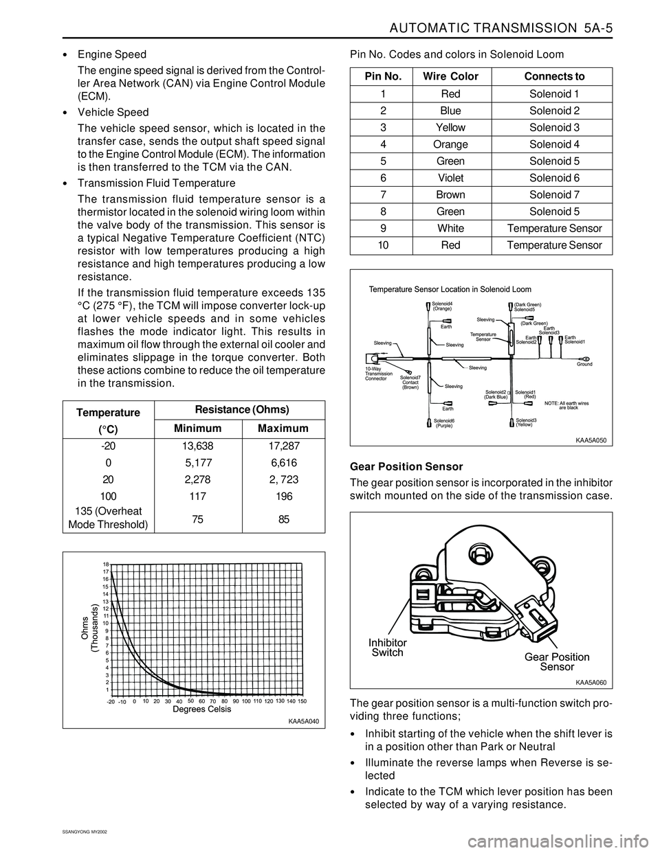
The transmission fluid temperature sensor is a
thermistor located in the solenoid wiring loom within
the valve body of the transmission. This sensor is
a typical Negative Temperature Coefficient (NTC)
resistor with low temperatures producing a high
resistance and high temperatures producing a low
resistance.
If the transmission fluid temperature exceeds 135
°C (275 °F), the TCM will impose converter lock-up
at lower vehicle speeds and in some vehicles
flashes the mode indicator light. This results in
maximum oil flow through the external oil cooler and
eliminates slippage in the torque converter. Both
these actions combine to reduce the oil temperature
in the transmission.
Minimum Temperature
(°C)Resistance (Ohms)
-20
0
20
100
135 (Overheat
Mode Threshold)13,638
5,177
2,278
117
75
Maximum
17,287
6,616
2, 723
196
85
Pin No. Wire ColorConnects to
1 Red Solenoid 1
2 BlueSolenoid 2
3 YellowSolenoid 3
4 OrangeSolenoid 4
5 GreenSolenoid 5
6 VioletSolenoid 6
7 BrownSolenoid 7
8 GreenSolenoid 5
9 White Temperature Sensor
10 Red Temperature Sensor
Pin No. Codes and colors in Solenoid Loom
KAA5A040KAA5A050
Gear Position Sensor
The gear position sensor is incorporated in the inhibitor
switch mounted on the side of the transmission case.
Inhibit starting of the vehicle when the shift lever is
in a position other than Park or Neutral
Illuminate the reverse lamps when Reverse is se-
lected
Indicate to the TCM which lever position has been
selected by way of a varying resistance. The gear position sensor is a multi-function switch pro-
viding three functions;
KAA5A060
Page 1100 of 2053
5A-6 AUTOMATIC TRANSMISSION
SSANGYONG MY2002
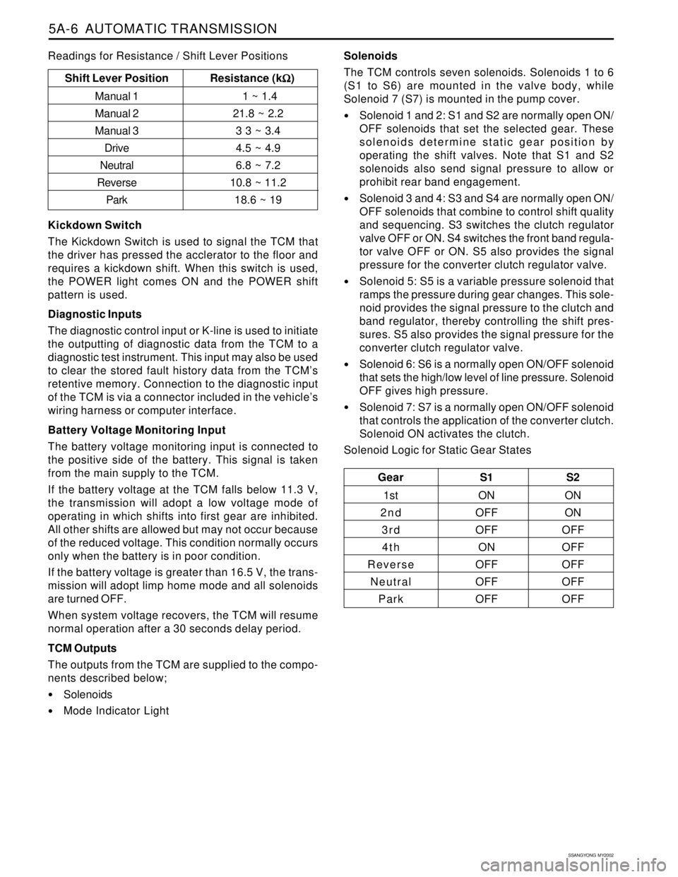
Solenoids
The TCM controls seven solenoids. Solenoids 1 to 6
(S1 to S6) are mounted in the valve body, while
Solenoid 7 (S7) is mounted in the pump cover.
Solenoid 1 and 2: S1 and S2 are normally open ON/
OFF solenoids that set the selected gear. These
solenoids determine static gear position by
operating the shift valves. Note that S1 and S2
solenoids also send signal pressure to allow or
prohibit rear band engagement.
Solenoid 3 and 4: S3 and S4 are normally open ON/
OFF solenoids that combine to control shift quality
and sequencing. S3 switches the clutch regulator
valve OFF or ON. S4 switches the front band regula-
tor valve OFF or ON. S5 also provides the signal
pressure for the converter clutch regulator valve.
Solenoid 5: S5 is a variable pressure solenoid that
ramps the pressure during gear changes. This sole-
noid provides the signal pressure to the clutch and
band regulator, thereby controlling the shift pres-
sures. S5 also provides the signal pressure for the
converter clutch regulator valve.
Solenoid 6: S6 is a normally open ON/OFF solenoid
that sets the high/low level of line pressure. Solenoid
OFF gives high pressure.
Solenoid 7: S7 is a normally open ON/OFF solenoid
that controls the application of the converter clutch.
Solenoid ON activates the clutch.
Solenoid Logic for Static Gear States
Gear S1 S2
1st ON ON
2nd OFF ON
3 r d OFF OFF
4th ON OFF
Reverse OFF OFF
Neutral OFF OFF
Park OFF OFF
Shift Lever Position Resistance (k
Ω ΩΩ Ω
Ω)
Manual 1 1 ~ 1.4
Manual 221.8 ~ 2.2
Manual 3 3 3 ~ 3.4
Drive4.5 ~ 4.9
Neutral6.8 ~ 7.2
Reverse10.8 ~ 11.2
Park18.6 ~ 19
Kickdown Switch
The Kickdown Switch is used to signal the TCM that
the driver has pressed the acclerator to the floor and
requires a kickdown shift. When this switch is used,
the POWER light comes ON and the POWER shift
pattern is used.
Diagnostic Inputs
The diagnostic control input or K-line is used to initiate
the outputting of diagnostic data from the TCM to a
diagnostic test instrument. This input may also be used
to clear the stored fault history data from the TCM’s
retentive memory. Connection to the diagnostic input
of the TCM is via a connector included in the vehicle’s
wiring harness or computer interface.
Battery Voltage Monitoring Input
The battery voltage monitoring input is connected to
the positive side of the battery. This signal is taken
from the main supply to the TCM.
If the battery voltage at the TCM falls below 11.3 V,
the transmission will adopt a low voltage mode of
operating in which shifts into first gear are inhibited.
All other shifts are allowed but may not occur because
of the reduced voltage. This condition normally occurs
only when the battery is in poor condition.
If the battery voltage is greater than 16.5 V, the trans-
mission will adopt limp home mode and all solenoids
are turned OFF.
When system voltage recovers, the TCM will resume
normal operation after a 30 seconds delay period.
TCM Outputs
The outputs from the TCM are supplied to the compo-
nents described below;
Solenoids
Mode Indicator Light Readings for Resistance / Shift Lever Positions
Page 1102 of 2053
5A-8 AUTOMATIC TRANSMISSION
SSANGYONG MY2002
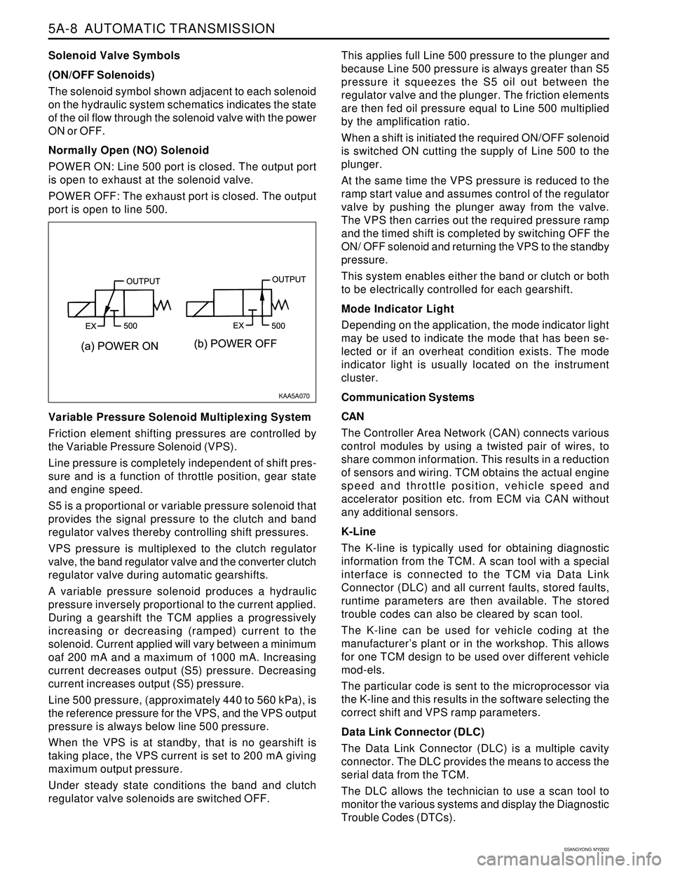
Solenoid Valve Symbols
(ON/OFF Solenoids)
The solenoid symbol shown adjacent to each solenoid
on the hydraulic system schematics indicates the state
of the oil flow through the solenoid valve with the power
ON or OFF.
Normally Open (NO) Solenoid
POWER ON: Line 500 port is closed. The output port
is open to exhaust at the solenoid valve.
POWER OFF: The exhaust port is closed. The output
port is open to line 500.
Variable Pressure Solenoid Multiplexing System
Friction element shifting pressures are controlled by
the Variable Pressure Solenoid (VPS).
Line pressure is completely independent of shift pres-
sure and is a function of throttle position, gear state
and engine speed.
S5 is a proportional or variable pressure solenoid that
provides the signal pressure to the clutch and band
regulator valves thereby controlling shift pressures.
VPS pressure is multiplexed to the clutch regulator
valve, the band regulator valve and the converter clutch
regulator valve during automatic gearshifts.
A variable pressure solenoid produces a hydraulic
pressure inversely proportional to the current applied.
During a gearshift the TCM applies a progressively
increasing or decreasing (ramped) current to the
solenoid. Current applied will vary between a minimum
oaf 200 mA and a maximum of 1000 mA. Increasing
current decreases output (S5) pressure. Decreasing
current increases output (S5) pressure.
Line 500 pressure, (approximately 440 to 560 kPa), is
the reference pressure for the VPS, and the VPS output
pressure is always below line 500 pressure.
When the VPS is at standby, that is no gearshift is
taking place, the VPS current is set to 200 mA giving
maximum output pressure.
Under steady state conditions the band and clutch
regulator valve solenoids are switched OFF.This applies full Line 500 pressure to the plunger and
because Line 500 pressure is always greater than S5
pressure it squeezes the S5 oil out between the
regulator valve and the plunger. The friction elements
are then fed oil pressure equal to Line 500 multiplied
by the amplification ratio.
When a shift is initiated the required ON/OFF solenoid
is switched ON cutting the supply of Line 500 to the
plunger.
At the same time the VPS pressure is reduced to the
ramp start value and assumes control of the regulator
valve by pushing the plunger away from the valve.
The VPS then carries out the required pressure ramp
and the timed shift is completed by switching OFF the
ON/ OFF solenoid and returning the VPS to the standby
pressure.
This system enables either the band or clutch or both
to be electrically controlled for each gearshift.
Mode Indicator Light
Depending on the application, the mode indicator light
may be used to indicate the mode that has been se-
lected or if an overheat condition exists. The mode
indicator light is usually located on the instrument
cluster.
Communication Systems
CAN
The Controller Area Network (CAN) connects various
control modules by using a twisted pair of wires, to
share common information. This results in a reduction
of sensors and wiring. TCM obtains the actual engine
speed and throttle position, vehicle speed and
accelerator position etc. from ECM via CAN without
any additional sensors.
K-Line
The K-line is typically used for obtaining diagnostic
information from the TCM. A scan tool with a special
interface is connected to the TCM via Data Link
Connector (DLC) and all current faults, stored faults,
runtime parameters are then available. The stored
trouble codes can also be cleared by scan tool.
The K-line can be used for vehicle coding at the
manufacturer’s plant or in the workshop. This allows
for one TCM design to be used over different vehicle
mod-els.
The particular code is sent to the microprocessor via
the K-line and this results in the software selecting the
correct shift and VPS ramp parameters.
Data Link Connector (DLC)
The Data Link Connector (DLC) is a multiple cavity
connector. The DLC provides the means to access the
serial data from the TCM.
The DLC allows the technician to use a scan tool to
monitor the various systems and display the Diagnostic
Trouble Codes (DTCs).
KAA5A070
Page 1137 of 2053
5A-42 AUTOMATIC TRANSMISSION
SSANGYONG MY2002
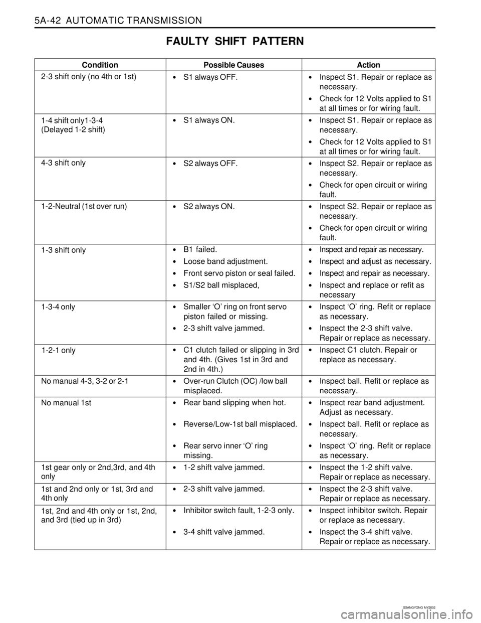
FAULTY SHIFT PATTERN
Condition
2-3 shift only (no 4th or 1st)Possible Causes
S1 always OFF.
S1 always ON.
S2 always OFF.
S2 always ON.
B1 failed.
Loose band adjustment.
Front servo piston or seal failed.
S1/S2 ball misplaced,
Smaller ‘O’ ring on front servo
piston failed or missing.
2-3 shift valve jammed.
C1 clutch failed or slipping in 3rd
and 4th. (Gives 1st in 3rd and
2nd in 4th.)
Over-run Clutch (OC) /low ball
misplaced.
Rear band slipping when hot.
Reverse/Low-1st ball misplaced.
Rear servo inner ‘O’ ring
missing.
1-2 shift valve jammed.
2-3 shift valve jammed.
Inhibitor switch fault, 1-2-3 only.
3-4 shift valve jammed.Action
Inspect S1. Repair or replace as
necessary.
Check for 12 Volts applied to S1
at all times or for wiring fault.
Inspect S1. Repair or replace as
necessary.
Check for 12 Volts applied to S1
at all times or for wiring fault.
Inspect S2. Repair or replace as
necessary.
Check for open circuit or wiring
fault.
Inspect S2. Repair or replace as
necessary.
Check for open circuit or wiring
fault.
Inspect and repair as necessary.
Inspect and adjust as necessary.
Inspect and repair as necessary.
Inspect and replace or refit as
necessary
Inspect ‘O’ ring. Refit or replace
as necessary.
Inspect the 2-3 shift valve.
Repair or replace as necessary.
Inspect C1 clutch. Repair or
replace as necessary.
Inspect ball. Refit or replace as
necessary.
Inspect rear band adjustment.
Adjust as necessary.
Inspect ball. Refit or replace as
necessary.
Inspect ‘O’ ring. Refit or replace
as necessary.
Inspect the 1-2 shift valve.
Repair or replace as necessary.
Inspect the 2-3 shift valve.
Repair or replace as necessary.
Inspect inhibitor switch. Repair
or replace as necessary.
Inspect the 3-4 shift valve.
Repair or replace as necessary.
1-4 shift only1-3-4
(Delayed 1-2 shift)
4-3 shift only
1-2-Neutral (1st over run)
1-3 shift only
1-3-4 only
1-2-1 only
No manual 4-3, 3-2 or 2-1
No manual 1st
1st gear only or 2nd,3rd, and 4th
only
1st and 2nd only or 1st, 3rd and
4th only
1st, 2nd and 4th only or 1st, 2nd,
and 3rd (tied up in 3rd)
Page 1149 of 2053
5A-54 AUTOMATIC TRANSMISSION
SSANGYONG MY2002
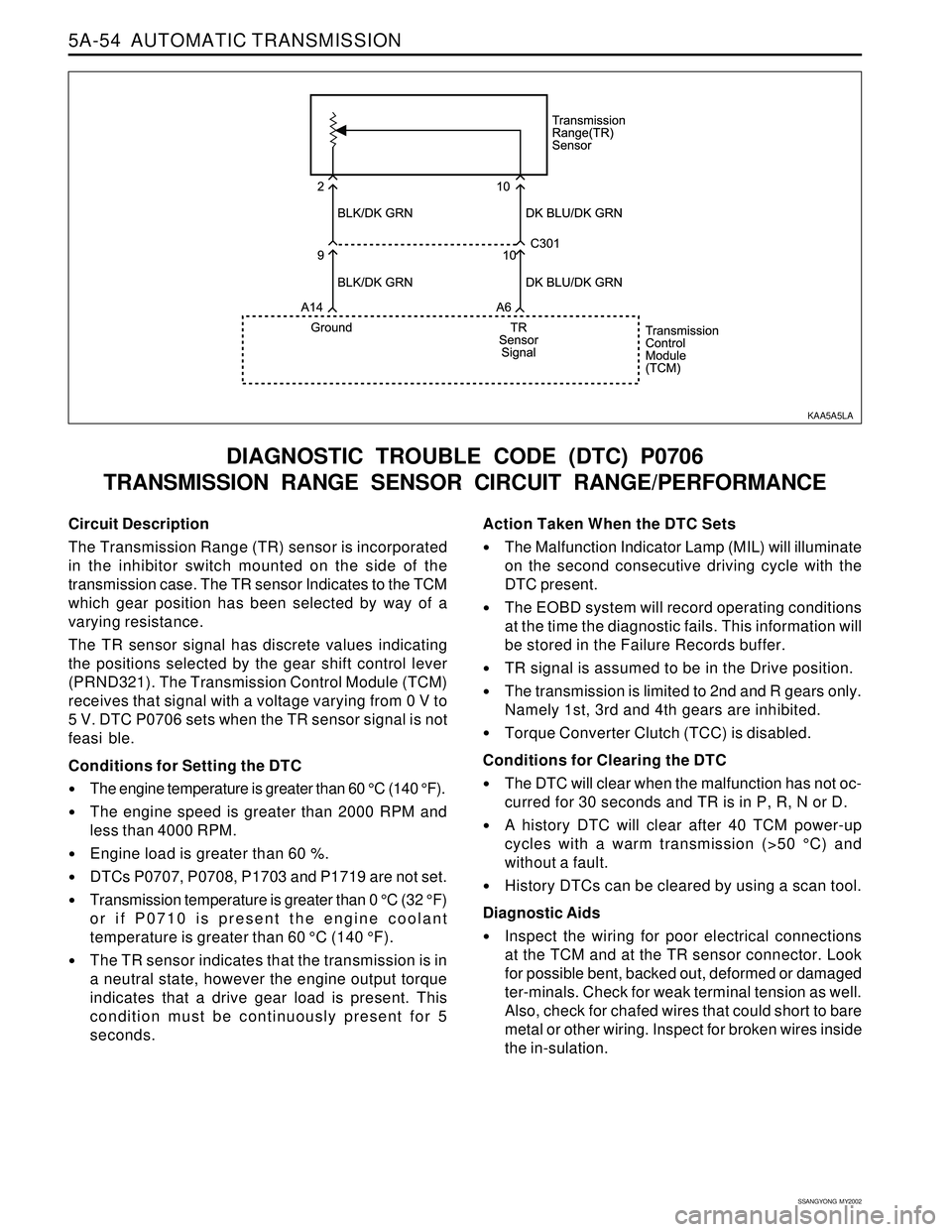
Circuit Description
The Transmission Range (TR) sensor is incorporated
in the inhibitor switch mounted on the side of the
transmission case. The TR sensor Indicates to the TCM
which gear position has been selected by way of a
varying resistance.
The TR sensor signal has discrete values indicating
the positions selected by the gear shift control lever
(PRND321). The Transmission Control Module (TCM)
receives that signal with a voltage varying from 0 V to
5 V. DTC P0706 sets when the TR sensor signal is not
feasi ble.
Conditions for Setting the DTC
•The engine temperature is greater than 60 °C (140 °F).
The engine speed is greater than 2000 RPM and
less than 4000 RPM.
Engine load is greater than 60 %.
DTCs P0707, P0708, P1703 and P1719 are not set.
Transmission temperature is greater than 0 °C (32 °F)
or if P0710 is present the engine coolant
temperature is greater than 60 °C (140 °F).
The TR sensor indicates that the transmission is in
a neutral state, however the engine output torque
indicates that a drive gear load is present. This
condition must be continuously present for 5
seconds.
DIAGNOSTIC TROUBLE CODE (DTC) P0706
TRANSMISSION RANGE SENSOR CIRCUIT RANGE/PERFORMANCE
Action Taken When the DTC Sets
The Malfunction Indicator Lamp (MIL) will illuminate
on the second consecutive driving cycle with the
DTC present.
The EOBD system will record operating conditions
at the time the diagnostic fails. This information will
be stored in the Failure Records buffer.
TR signal is assumed to be in the Drive position.
The transmission is limited to 2nd and R gears only.
Namely 1st, 3rd and 4th gears are inhibited.
Torque Converter Clutch (TCC) is disabled.
Conditions for Clearing the DTC
The DTC will clear when the malfunction has not oc-
curred for 30 seconds and TR is in P, R, N or D.
A history DTC will clear after 40 TCM power-up
cycles with a warm transmission (>50 °C) and
without a fault.
History DTCs can be cleared by using a scan tool.
Diagnostic Aids
Inspect the wiring for poor electrical connections
at the TCM and at the TR sensor connector. Look
for possible bent, backed out, deformed or damaged
ter-minals. Check for weak terminal tension as well.
Also, check for chafed wires that could short to bare
metal or other wiring. Inspect for broken wires inside
the in-sulation.
KAA5A5LA
Page 1151 of 2053
5A-56 AUTOMATIC TRANSMISSION
SSANGYONG MY2002
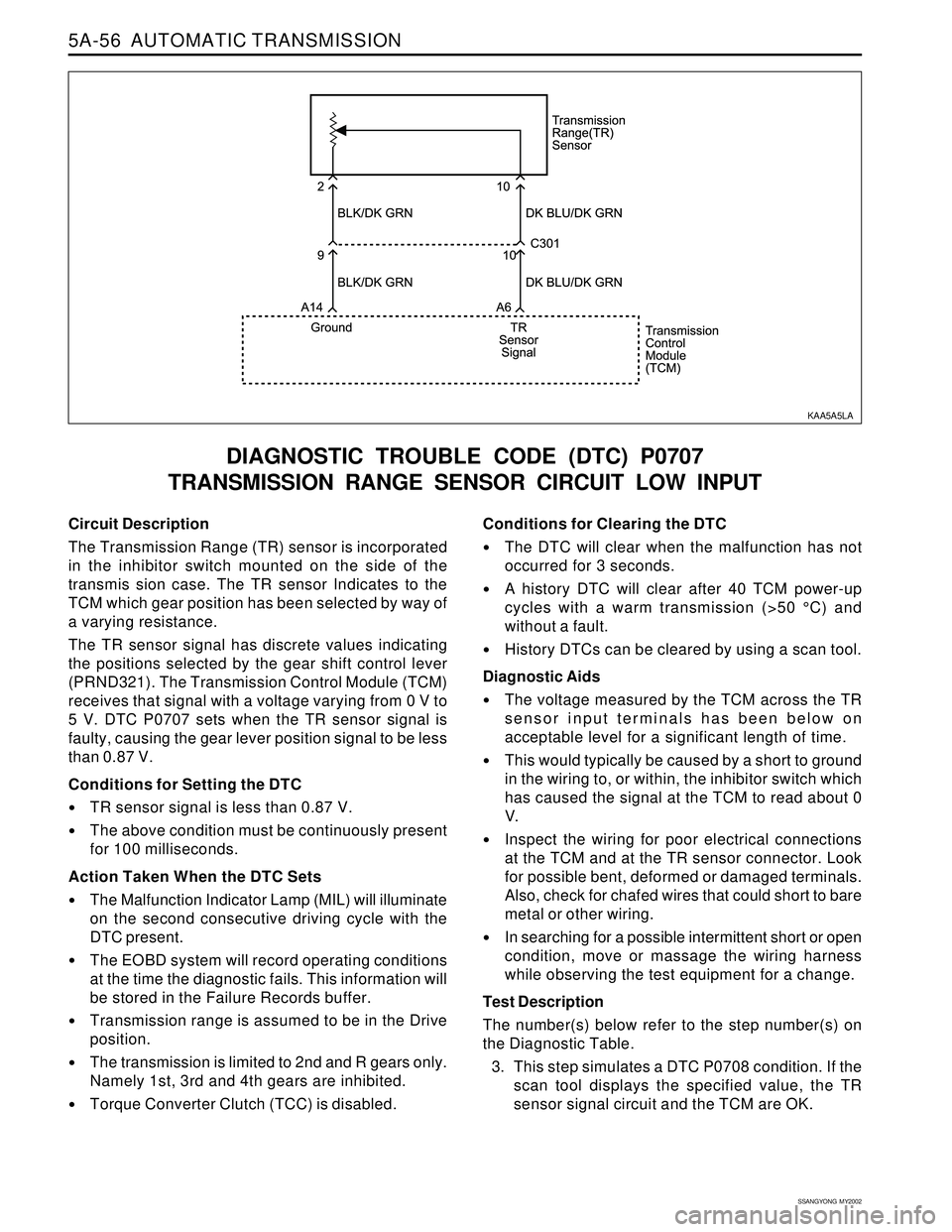
Circuit Description
The Transmission Range (TR) sensor is incorporated
in the inhibitor switch mounted on the side of the
transmis sion case. The TR sensor Indicates to the
TCM which gear position has been selected by way of
a varying resistance.
The TR sensor signal has discrete values indicating
the positions selected by the gear shift control lever
(PRND321). The Transmission Control Module (TCM)
receives that signal with a voltage varying from 0 V to
5 V. DTC P0707 sets when the TR sensor signal is
faulty, causing the gear lever position signal to be less
than 0.87 V.
Conditions for Setting the DTC
TR sensor signal is less than 0.87 V.
The above condition must be continuously present
for 100 milliseconds.
Action Taken When the DTC Sets
The Malfunction Indicator Lamp (MIL) will illuminate
on the second consecutive driving cycle with the
DTC present.
The EOBD system will record operating conditions
at the time the diagnostic fails. This information will
be stored in the Failure Records buffer.
Transmission range is assumed to be in the Drive
position.
The transmission is limited to 2nd and R gears only.
Namely 1st, 3rd and 4th gears are inhibited.
Torque Converter Clutch (TCC) is disabled.
DIAGNOSTIC TROUBLE CODE (DTC) P0707
TRANSMISSION RANGE SENSOR CIRCUIT LOW INPUT
Conditions for Clearing the DTC
The DTC will clear when the malfunction has not
occurred for 3 seconds.
A history DTC will clear after 40 TCM power-up
cycles with a warm transmission (>50 °C) and
without a fault.
History DTCs can be cleared by using a scan tool.
Diagnostic Aids
The voltage measured by the TCM across the TR
sensor input terminals has been below on
acceptable level for a significant length of time.
This would typically be caused by a short to ground
in the wiring to, or within, the inhibitor switch which
has caused the signal at the TCM to read about 0
V.
Inspect the wiring for poor electrical connections
at the TCM and at the TR sensor connector. Look
for possible bent, deformed or damaged terminals.
Also, check for chafed wires that could short to bare
metal or other wiring.
In searching for a possible intermittent short or open
condition, move or massage the wiring harness
while observing the test equipment for a change.
Test Description
The number(s) below refer to the step number(s) on
the Diagnostic Table.
3. This step simulates a DTC P0708 condition. If the
scan tool displays the specified value, the TR
sensor signal circuit and the TCM are OK.
KAA5A5LA