Page 513 of 2053

M161 ENGINE CONTROLS 1F2 -- 95
D AEW OO M Y_2000
MAINTENANCE AND REPAIR
YAA1F700
ON VEHICLE SERVICE
DISCHARGING THE PRESSURE IN
FUEL SYSTEM
Removal and Installation Procedure
1. Remove the fuel pressure test connector.
Installation Notice
Tightening Torque
25 NSm (18 lb-ft)
YAA1F710
2. Remove the fuel pressure in fuel system by pressing
the service valve with a clean, pointy tool.
Notice:Place a cloth so that the fuel doesn’t stain
around.
3. Installation should follow the removal procedure in
the reverse order.
YAA1F170
FUEL PUMP
Tools Required
661 589 00 46 00 Fuel Tank Cap Wrench
Removal and Installation Procedure
Caution: The fuel system is under pressure. To
avoid fuel spillage and the risk of personal injury or
fire, it is necessary to relieve the fuel system pres -
sure before disconnecting the fuel lines.
1. Relieve the fuel system pressure. Refer to “Discharg-
ing the Pressure in Fuel System” in this section.
2. Disconnect the negative battery cable.
3. Put aside the floor carpet to remove the fuel pump ac-
cess cover.
4. Remove the fuel pump access cover.
5. Remove the fuel pump wiring connectors.
6. Disconnect the fuel supply and return pipes.
7. Remove the fuel pump locking cap band.
Page 524 of 2053
D AEW OO M Y_2000
SECTION 1G2
M161 ENGINE INTAKE & EXHAUST
CAUTION: Disconnect the negative battery cable before removing or installing any electrical unit or when a
tool or equipment could easily come in contact with exposed electrical terminals. Disconnecting this cable
will help prevent personal injury and damage to the vehicle. The ignition must also be in LOCK unless other -
wise noted.
TABLE OF CONTENTS
Specifications 1G2 -- 2...........................
Fastener Tightening Specifications 1G2 -- 2.........
Maintenance and Repair 1G2 -- 3..................
On-- Vehicle Service 1G2-- 3........................
Air Cleaner 1G2-- 3.............................
Air Intake Shield 1G2-- 5.........................Intake Air Duct 1G2--6..........................
Intake Manifold 1G2--8.........................
Exhaust Manifold 1G2-- 10.......................
Removal and Installation of Exhaust
System 1G2-- 12.............................
Page 526 of 2053
M161 ENGINE INTAKE & EXHAUST 1G2 -- 3
D AEW OO M Y_2000
MAINTENANCE AND REPAIR
ON -- VEHICLE SERVICE
AIR CLEANER
1 Air Cleaner Assembly
2 Element Assembly
3 Insulator4 Air Duct Hose
6 Bolt (M8 x 30 ) 22.5-- 27.5 NSm ...............
Page 551 of 2053

D AEW OO M Y_2000
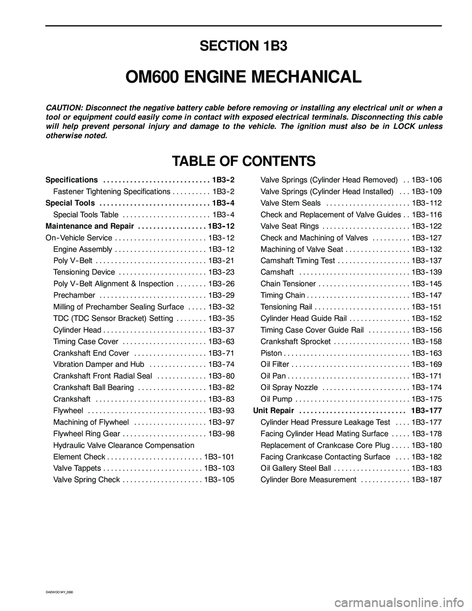
SECTION 1B3
OM600 ENGINE MECHANICAL
CAUTION: Disconnect the negative battery cable before removing or installing any electrical unit or when a
tool or equipment could easily come in contact with exposed electrical terminals. Disconnecting this cable
will help prevent personal injury and damage to the vehicle. The ignition must also be in LOCK unless
otherwise noted.
TABLE OF CONTENTS
Specifications 1B3 -- 2............................
Fastener Tightening Specifications 1B3 -- 2..........
Special Tools 1B3 -- 4.............................
Special Tools Table 1B3-- 4.......................
Maintenance and Repair 1B3 -- 12..................
On-- Vehicle Service 1B3-- 12........................
Engine Assembly 1B3-- 12........................
Poly V-- Belt 1B3 -- 21.............................
Tensioning Device 1B3-- 23.......................
Poly V-- Belt Alignment & Inspection 1B3-- 26........
Prechamber 1B3-- 29............................
Milling of Prechamber Sealing Surface 1B3 -- 32.....
TDC (TDC Sensor Bracket) Setting 1B3 -- 35........
Cylinder Head 1B3-- 37...........................
Timing Case Cover 1B3 -- 63......................
Crankshaft End Cover 1B3-- 71...................
Vibration Damper and Hub 1B3-- 74...............
Crankshaft Front Radial Seal 1B3-- 80.............
Crankshaft Ball Bearing 1B3-- 82..................
Crankshaft 1B3-- 83.............................
Flywheel 1B3 -- 93...............................
Machining of Flywheel 1B3-- 97...................
Flywheel Ring Gear 1B3 -- 98......................
Hydraulic Valve Clearance Compensation
Element Check 1B3-- 101.........................
Valve Tappets 1B3-- 103..........................
Valve Spring Check 1B3-- 105.....................Valve Springs (Cylinder Head Removed) 1B3-- 106..
Valve Springs (Cylinder Head Installed) 1B3-- 109...
Valve Stem Seals 1B3-- 112......................
Check and Replacement of Valve Guides 1B3-- 116..
Valve Seat Rings 1B3-- 122.......................
Check and Machining of Valves 1B3-- 127..........
Machining of Valve Seat 1B3-- 132.................
Camshaft Timing Test 1B3-- 137...................
Camshaft 1B3-- 139.............................
Chain Tensioner 1B3-- 145........................
Timing Chain 1B3-- 147...........................
Tensioning Rail 1B3-- 151.........................
Cylinder Head Guide Rail 1B3-- 152................
Timing Case Cover Guide Rail 1B3-- 156...........
Crankshaft Sprocket 1B3-- 158....................
Piston 1B3-- 163.................................
Oil Filter 1B3-- 169...............................
Oil Pan 1B3-- 171................................
Oil Spray Nozzle 1B3-- 174.......................
Oil Pump 1B3-- 175..............................
Unit Repair 1B3 -- 177............................
Cylinder Head Pressure Leakage Test 1B3-- 177....
Facing Cylinder Head Mating Surface 1B3 -- 178.....
Replacement of Crankcase Core Plug 1B3-- 180.....
Facing Crankcase Contacting Surface 1B3 -- 182....
Oil Gallery Steel Ball 1B3-- 183....................
Cylinder Bore Measurement 1B3-- 187.............
Page 561 of 2053
1B3 -- 12 OM600 ENGINE MECHANICAL
D AEW OO M Y_2000
MAINTENANCE AND REPAIR
ON -- VEHICLE SERVICE
ENGINE ASSEMBLY
Page 737 of 2053

D AEW OO M Y_2000
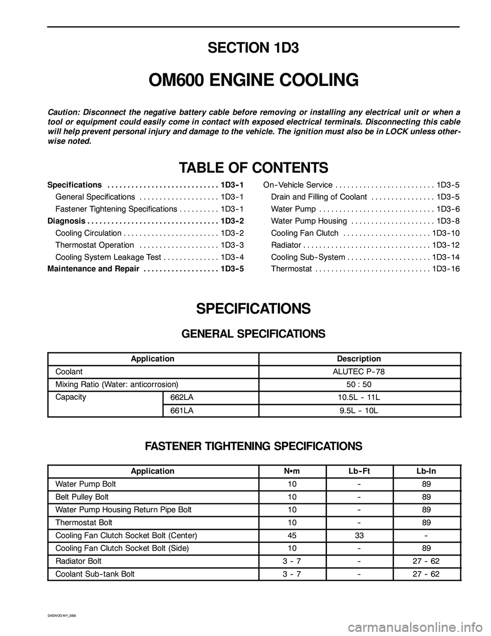
SECTION 1D3
OM600 ENGINE COOLING
Caution: Disconnect the negative battery cable before removing or installing any electrical unit or when a
tool or equipment could easily come in contact with exposed electrical terminals. Disconnecting this cable
will help prevent personal injury and damage to the vehicle. The ignition must also be in LOCK unless other -
wise noted.
TABLE OF CONTENTS
Specifications 1D3 -- 1............................
General Specifications 1D3-- 1....................
Fastener Tightening Specifications 1D3 -- 1..........
Diagnosis 1D3 -- 2.................................
Cooling Circulation 1D3 -- 2........................
Thermostat Operation 1D3 -- 3....................
Cooling System Leakage Test 1D3-- 4..............
Maintenance and Repair 1D3 -- 5...................On-- Vehicle Service 1D3-- 5.........................
Drain and Filling of Coolant 1D3 -- 5................
Wat er Pum p 1D3 -- 6.............................
Water Pump Housing 1D3-- 8.....................
Cooling Fan Clutch 1D3 -- 10......................
Radiator 1D3-- 12................................
Cooling Sub-- System 1D3-- 14.....................
Thermostat 1D3 -- 16.............................
SPECIFICATIONS
GENERAL SPECIFICATIONS
ApplicationDescription
CoolantALUTEC P-- 78
Mixing Ratio (Water: anticorrosion)50 : 50
Capacity662LA10.5L -- 11Lpy
661LA9.5L -- 10L
FASTENER TIGHTENING SPECIFICATIONS
ApplicationNSmLb-- FtLb-In
Water Pump Bolt10--89
Belt Pulley Bolt10--89
Water Pump Housing Return Pipe Bolt10--89
Thermostat Bolt10--89
Cooling Fan Clutch Socket Bolt (Center)4533--
Cooling Fan Clutch Socket Bolt (Side)10--89
Radiator Bolt3--7--27 -- 62
Coolant Sub-- tank Bolt3--7--27 -- 62
Page 740 of 2053
OM600 ENGINE COOLING 1D3 -- 5
D AEW OO M Y_2000
MAINTENANCE AND REPAIR
ON -- VEHICLE SERVICE
DRAIN AND FILLING OF COOLANT
Preceding Work : Removal of skid plate
Drain / Filling
1. Loosen the pressure cap of reservoir by 1 notch and
remove pressure and then loosen the cap.
Notice
Do not remove radiator cap when coolant is above
90°C.
2. Open the drain plug and drain the coolant.
Notice
Collect the coolant by using the proper bottle.
3. Remove the drain plug(1) and seal(2) of cylinder
block and drain the coolant.
4. Replace the seal to new one and tighten the drain
plug.
Installation Notice
Tightening Torque30 N∙m (22 lb-ft)
5. Tighten the drain plug of the lower radiator.
6. Fill the coolant through coolant reservoir -- tank.
Notice
DA proportion of 50% by volume of water / anticor-
rosion must be ensured.
7. After engine is running at idle speed, check the level
of coolant. If necessary, add enough specified cool-
ant.
Page 753 of 2053
D AEW OO M Y_2000
SECTION 1E3
OM600 ENGINE ELECTRICAL
Caution: Disconnect the negative battery cable before removing or installing any electrical unit or when a
tool or equipment could easily come in contact with exposed electrical terminals. Disconnecting this cable
will help prevent personal injury and damage to the vehicle. The ignition must also be in LOCK unless other -
wise noted.
TABLE OF CONTENTS
Specifications 1E3 -- 1............................
General Specifications 1E3-- 1....................
Maintenance and Repair 1E3 -- 2...................
On-- Vehicle Service 1E3-- 2.........................Glow Plug 1E3-- 2...............................
Generator 1E3-- 6...............................
Starter Motor 1E3-- 8............................
SPECIFICATIONS
GENERAL SPECIFICATIONS
ApplicationDescription
Generator12V -- 75A
Starter12V -- 2.2kW
Glow Plug11. 5 V