Page 1456 of 2053
POWER STEERING SYSTEM 6A-5
SSANGYONG MY2002
BLEEDING THE POWER
STEERING SYSTEM
1. Disconnect the fuel line. Using a starter motor,
crank the engine and turn the steering wheel from
lock to start 5 or 6 times.
Notice: Do bleeding with engine cranking. If bleed
with idling, there can be a air contact with oil.
2. Connect the fuel feed line and start the engine at
idle speed.
3. Turn the steering wheel from lock to lock until there
is no more air in oil reservoir.
4. Connect the oil level is within specification.
5. By turning the steering wheel left to right, check
the oil level change.
Notice: If oil is not changes more than 5 mm, do
bleeding again. If oil level rises suddenly when
stopped engine, again.
MAINTENANCE
CHECKING AND ADDING FLUID
Notice: When adding fluid or making a complete fluid
change, always use DEXRON. - II power steering fluid.
Failure to use the proper fluid will cause hose and seal
damage and fluid leaks.
1. The power steering fluid level is indicated by marks
on a fluid level indicator on the fluid reservoir cap.
2. If the fluid is warmed up to 66 °C (150 °F), the fluid
level should be between the MAX and MIN marks.
Add fluid as needed.
3. If the fluid is cool, 21 °C (70 °F), the fluid level should
be at the MIN mark. Add fluid as needed.
Page 1519 of 2053
SSANGYONG MY2002
7A-18 HEATING AND VENTILATION SYSTEM
ON-VEHICLE SERVICE
TEMPREATURE CONTROL CABLE
ADJUSTMENT
Because the cable and the cable housing have fixed
lengths, it is impossible to make a temperature cable
adjustment.
The heater/air distributor case linkage also cannot be
adjusted.
If a malfunction is suspected, verify the proper
operation of the controller and the mechanical doors
for heater/air distributor case assembly.
MAINTENANCE AND REPAIR
KAA7A020
KAA7A030
CONTROLLER ASSEMBLY AND
TEMPERATURE CONTROL CABLE
Removal and installation Procedure
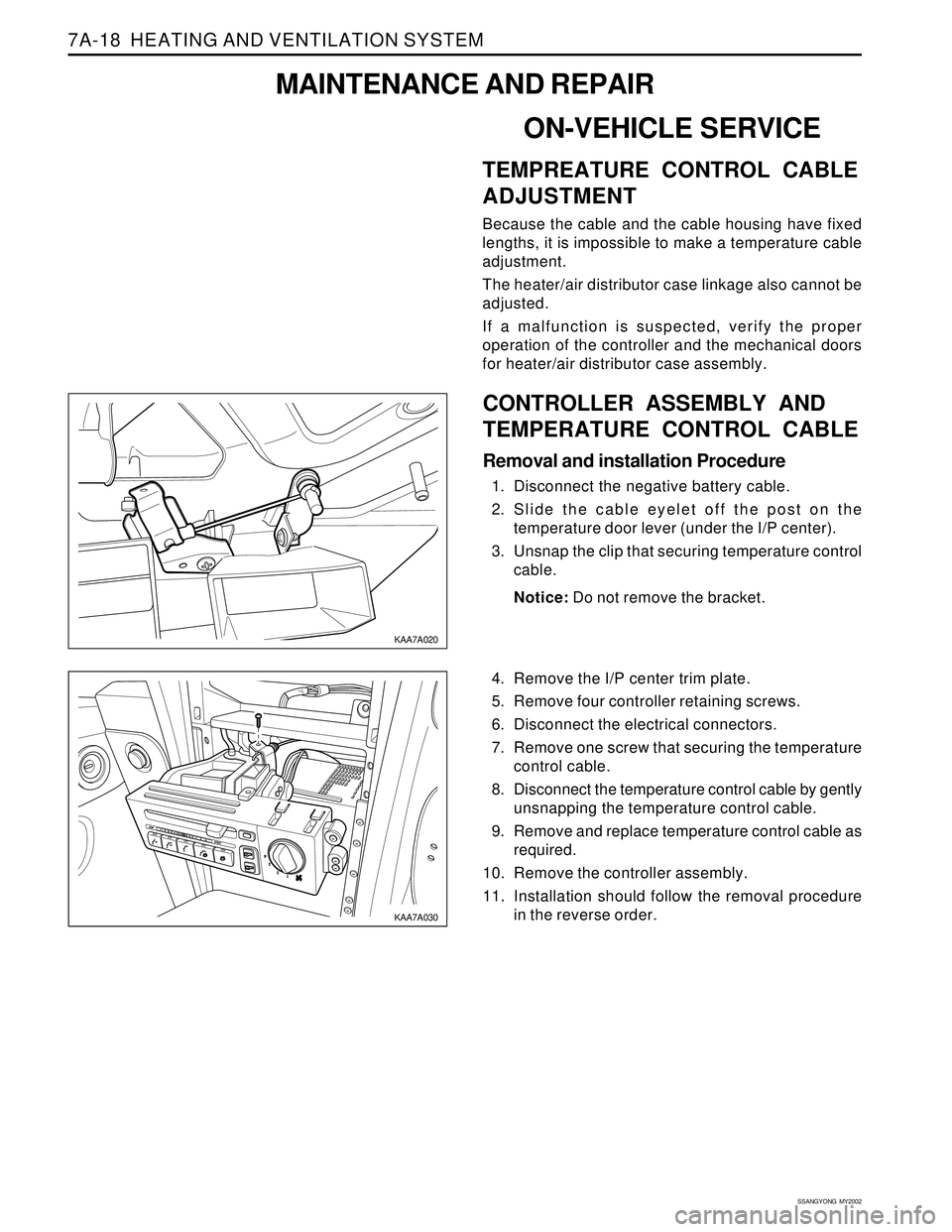
1. Disconnect the negative battery cable.
2. Slide the cable eyelet off the post on the
temperature door lever (under the I/P center).
3. Unsnap the clip that securing temperature control
cable.
Notice: Do not remove the bracket.
4. Remove the I/P center trim plate.
5. Remove four controller retaining screws.
6. Disconnect the electrical connectors.
7. Remove one screw that securing the temperature
control cable.
8. Disconnect the temperature control cable by gently
unsnapping the temperature control cable.
9. Remove and replace temperature control cable as
required.
10. Remove the controller assembly.
11. Installation should follow the removal procedure
in the reverse order.
Page 1530 of 2053
SECTION 7C
MANUAL CONTROL / SEMIAUTO
TEMPERATURE CONTROL HEATING,
VENTILATION AND AIR CONDITIONING
SYSTEM
CAUTION: Disconnect the negative battery cable before removing or installing any electrical unit or when
a tool or equipment could easily come in contact with exposed electrical terminals. Disconnecting this
cable will help prevent personal injury and damage to the vehicle. The ignition must also be in LOCK
unless other-wise noted.
TABLE OF CONTENTS
Specifications.......................................................7C-2
Refrigerant..........................................................7C-2
Evaporator Unit....................................................7C-2
Blower Unit..........................................................7C-2
Compressor.........................................................7C-2
Condenser...........................................................7C-2
Receiver Drier......................................................7C-2
Pressure Switch...................................................7C-3
Air Filter...............................................................7C-3
Heater Unit..........................................................7C-3
Fastener Tightening Specifications.......................7C-3
Diagnosis..............................................................7C-4
Defectives in Fan Motor Circuit.............................7C-5
Defectives in Compressor Circuit.........................7C-6
Diagnosis Using the Manifold Gauge...................7C-7Component Locator.............................................7C-9
Ventilation............................................................7C-9
Heater System ................................................... 7C-11
Air Conditioner System...................................... 7C-12
Diesel Engine .................................................... 7C-12
Gasoline Engine................................................ 7C-13
Maintenance and Repair................................... 7C-14
Refrigerant Charging .......................................... 7C-14
Compressor Oil Replacement............................ 7C-18
Repair Instructions.............................................. 7C-19
On-Vehicle Service............................................... 7C-19
Condener.......................................................... 7C-19
Receiver Drier.................................................... 7C-21
Air - Conditioner Compressor............................. 7C-23
Heater and Air Conditioner Control Box.............. 7C-24
Air Filter............................................................. 7C-25
Page 1543 of 2053
SSANGYONG MY2002
7C-14 MANUAL & SEMIAUTO-HVAC
REFRIGERANT CHARGING
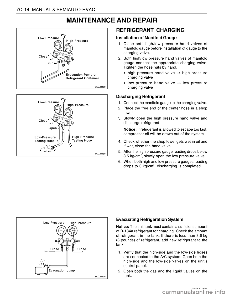
Installation of Manifold Gauge
1. Close both high/low pressure hand valves of
manifold gauge before installation of gauge to the
charging valve.
2. Both high/low pressure hand valves of manifold
gauge connect the appropriate charging valve.
Tighten the hose nuts by hand.
high pressure hand valve → high pressure
charging valve
low pressure hand valve → low pressure
charging valve
Discharging Refrigerant
1. Connect the manifold gauge to the charging valve.
2. Place the free end of the center hose in a shop
towel.
3. Slowly open the high pressure hand valve and
discharge refrigerant.
Notice: If refrigerant is allowed to escape too fast,
compressor oil will be drawn out of the system.
4. Check whether the shop towel gets wet in oil and
if wet, close the hand valve.
5. After the high pressure gauge reading drops below
3.5 kg/cm
2, slowly open the low pressure valve.
6. When both high and low pressure gauges reading
drops to 0 kg/cm
2, discharging is completed.
Evacuating Refrigeration System
Notice: The unit tank must contain a sufficient amount
of R-134a refrigerant for charging. Check the amount
of refrigerant in the tank. If there is less than 3.6 kg
(8 pounds) of refrigerant, add new refrigerant to the
tank.
1. Verify that the high-side and the low-side hoses
are connected to the A/C system. Open both the
high-side and the low-side valves on the unit’s
control panel.
2. Open both the gas and the liquid valves on the
tank.
YAD7B150
YAD7B160
YAD7B170
MAINTENANCE AND REPAIR
Page 1555 of 2053
SECTION 7D
FULL AUTOMATIC TEMPERATURE
CONTROL HEATING, VENTILATION AND
AIR CONDITIONING SYSTEM
FATC (Full Automatic Temperature Control) is full automatic heater and airconditioning system that detects
incar temperature, ambient temperature, sun load and coolant temperature and controls airconditioner
system blowing capacity, outlet temperature and intaking/outlet mode to maintain interior comfort.
TABLE OF CONTENTS
Specifications.......................................................7D-2
Refrigerant..........................................................7D-2
Evaporator Unit....................................................7D-2
Blower Unit..........................................................7D-2
Compressor.........................................................7D-2
Condenser...........................................................7D-2
Receiver Drier......................................................7D-2
Pressure Switch...................................................7D-3
Air Filter...............................................................7D-3
Heater Unit..........................................................7D-3
Service Specifications ..........................................7D-4
Fastener Tightening Specifications.......................7D-4Schematic and Routing Diagrams.......................7D-5
Circuit Diagram....................................................7D-5
FATC Block Diagram...........................................7D-6
Component Locator.............................................7D-7
Ventilation System...............................................7D-7
Function Description............................................7D-8
Diagnosis..............................................................7D-9
Diagnosis Test.....................................................7D-9
Maintenance and Repair................................... 7D-13
FATC Control Panel............................................ 7D-13
Air Filter............................................................. 7D-16
Troubleshooting................................................. 7D-17
Page 1567 of 2053
FATC-HAVC 7D-13
SSANGYONG MY2002
MAINTENANCE AND REPAIR
FATC CONTROL PANEL
KAA7D070
1 AUTO Switch
2 MODE Switch
3 OFF Switch
4 Temperature UP/DOWN Switch
5 Defrost Switch6 Airconditioner Switch
7 Fresh/Recirculation Switch
8 Blower Switch (UP/DOWN)
9 VFD (Vacuum Fluorescent Display)
Page 1769 of 2053
SECTION 9I
WATERLEAKS
CAUTION: Disconnect the negative battery cable before removing or installing any electrical unit or when a
tool or equipment could easily come in contact with exposed electrical terminals. Disconnecting this cable
will help prevent personal injury and damage to the vehicle. The ignition must also be in LOCK unless
otherwise noted.
TABLE OF CONTENTS
Specifications........................................................9I-2
Recommended Materials for Waterleak Repairs....9I-2
Watertest Stand Specifications.............................9I-2
Diagnosis...............................................................9I-3Waterleak Diagnosis.............................................9I-3
Maintenance and Repair......................................9I-6
On-Vehicle Service..................................................9I-6
Waterleak Repair..................................................9I-6
Page 1774 of 2053
SSANGYONG MY2002
9I-6 WATERLEAKS
KAA9I080
6. Using a sharp knife, trim off the uneven edges of
the adhesive material around the leak 75 to 100
mm (3 to 4 inches) on both sides of the leak.
KAA9I070
ON-VEHICLE SERVICE
WATERLEAK REPAIR
Some waterleaks around the glass can be repaired
without removing the glass.
Important: This type of repair may be used only for
urethane-installed glass.
1. Remove the reveal molding in the area of the leak.
It may be necessary to remove the garnish molding
or the trim strip lace in order to locate the leak.
2. While spraying water over the leak area, carefully
push the glass outward in order to determine the
size of the leak.
3. Mark the location of the leak.
4. Use water to clean any dirt from the area. Dry the
area with an air hose.
5. Using a sharp knife, trim off the uneven edges of
the adhesive caulking material around the leak for
a distance of 75 to 100 mm (3 to 4 inches) on both
sides of the leak.
MAINTENANCE AND REPAIR