Page 1309 of 2053

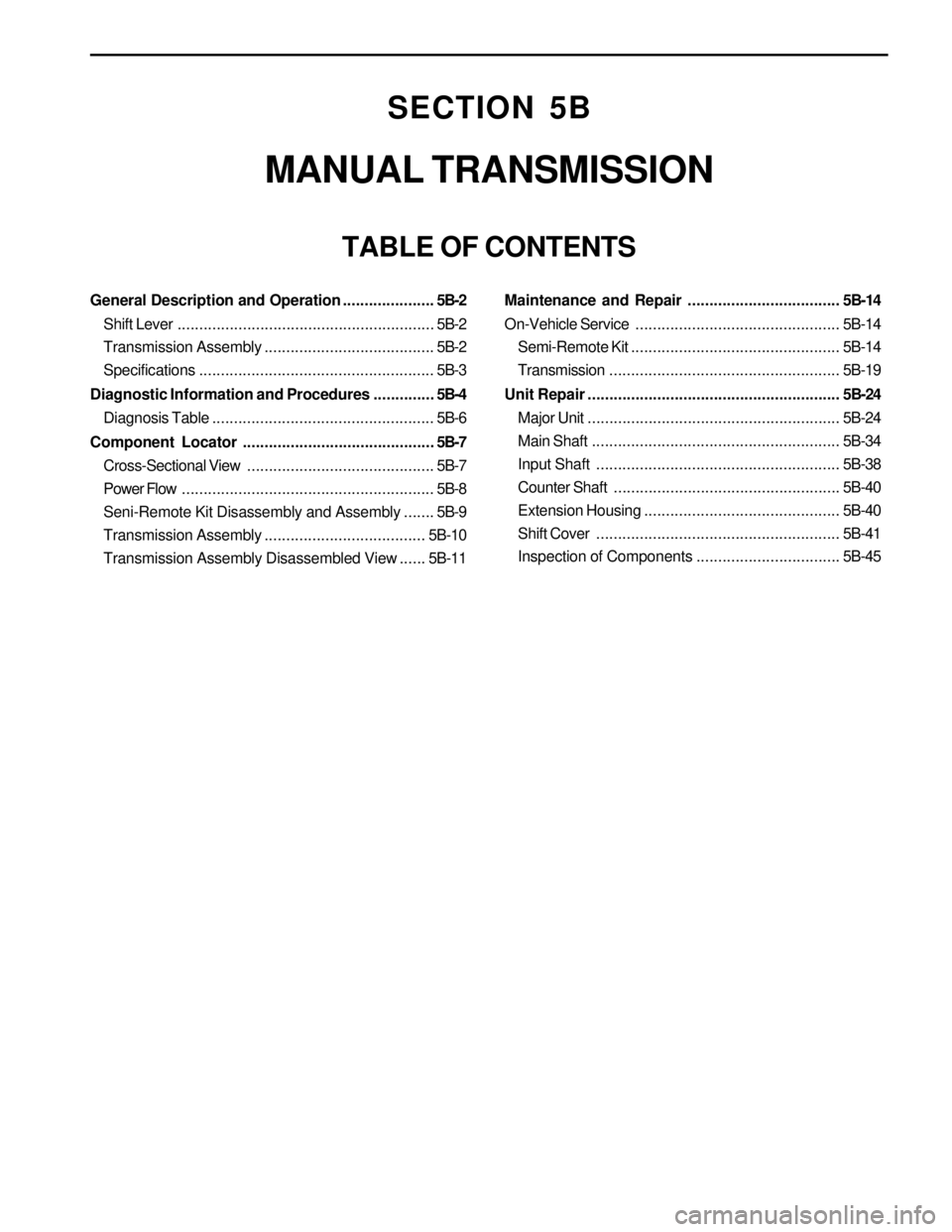
SECTION 5B
MANUAL TRANSMISSION
TABLE OF CONTENTS
General Description and Operation.....................5B-2
Shift Lever...........................................................5B-2
Transmission Assembly.......................................5B-2
Specifications......................................................5B-3
Diagnostic Information and Procedures..............5B-4
Diagnosis Table...................................................5B-6
Component Locator............................................5B-7
Cross-Sectional View ...........................................5B-7
Power Flow..........................................................5B-8
Seni-Remote Kit Disassembly and Assembly.......5B-9
Transmission Assembly.....................................5B-10
Transmission Assembly Disassembled View......5B-11Maintenance and Repair................................... 5B-14
On-Vehicle Service...............................................5B-14
Semi-Remote Kit................................................5B-14
Transmission.....................................................5B-19
Unit Repair.......................................................... 5B-24
Major Unit..........................................................5B-24
Main Shaft.........................................................5B-34
Input Shaft........................................................5B-38
Counter Shaft....................................................5B-40
Extension Housing.............................................5B-40
Shift Cover........................................................5B-41
Inspection of Components.................................5B-45
Page 1322 of 2053
SSANGYONG MY2002
5B-14 MANUAL TRANSMISSION
ON-VEHICLE SERVICE
SEMI-REMOTE KIT
Removal Procedure
1. Remove the control housing arm insulator from the
semi-remote kit.
YAD5B120
YAD5B140
YAD5B130
2. Remove two snap rings and two screws using the
snap ring plier.
Notice: Do not reuse the damaged snap ring.
3. Disconnect the shift rod pin using the punch.
MAINTENANCE AND REPAIR
Page 1357 of 2053

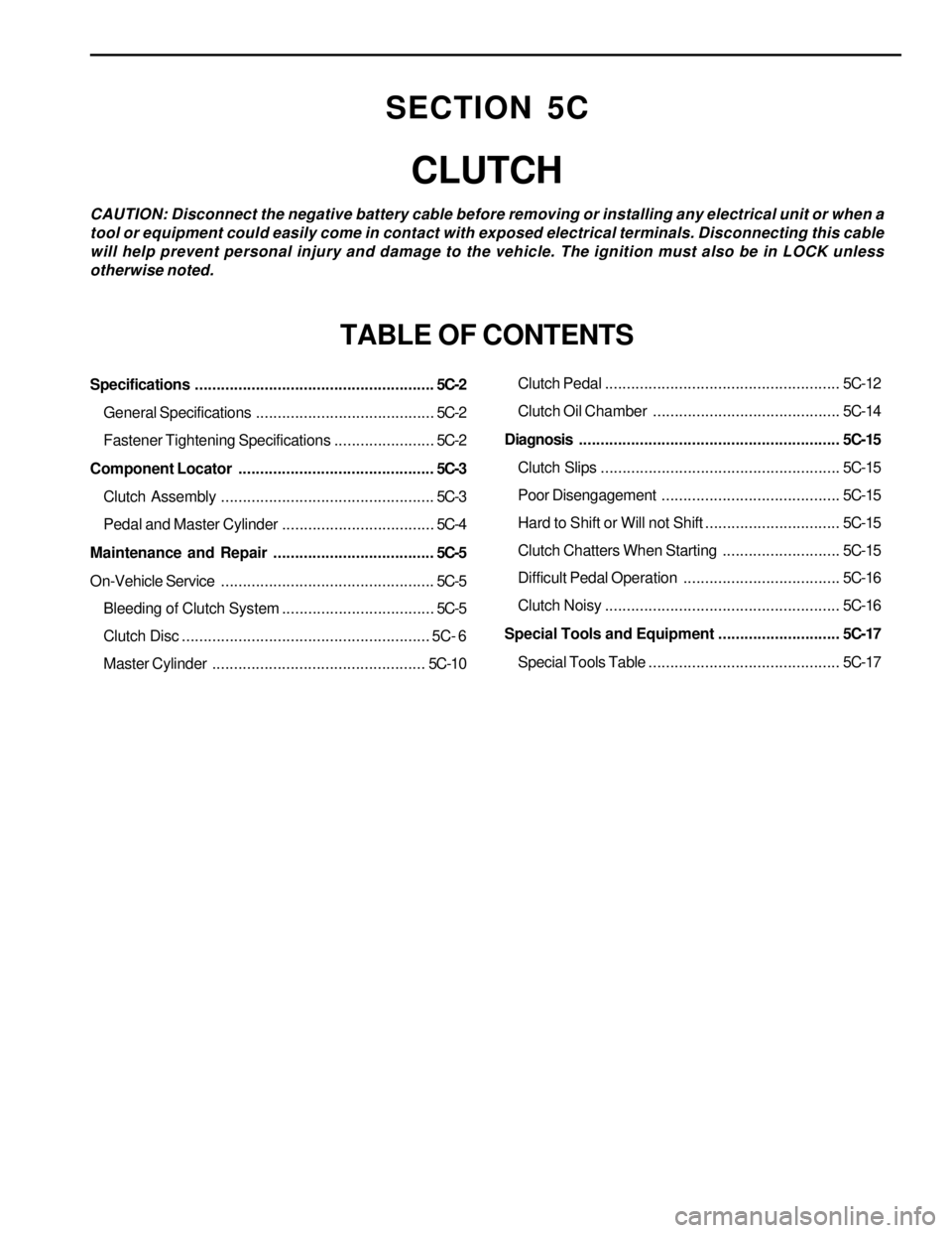
Specifications.......................................................5C-2
General Specifications.........................................5C-2
Fastener Tightening Specifications.......................5C-2
Component Locator.............................................5C-3
Clutch Assembly.................................................5C-3
Pedal and Master Cylinder...................................5C-4
Maintenance and Repair.....................................5C-5
On-Vehicle Service.................................................5C-5
Bleeding of Clutch System...................................5C-5
Clutch Disc......................................................... 5C- 6
Master Cylinder.................................................5C-10Clutch Pedal...................................................... 5C-12
Clutch Oil Chamber........................................... 5C-14
Diagnosis............................................................ 5C-15
Clutch Slips....................................................... 5C-15
Poor Disengagement ......................................... 5C-15
Hard to Shift or Will not Shift............................... 5C-15
Clutch Chatters When Starting........................... 5C-15
Difficult Pedal Operation.................................... 5C-16
Clutch Noisy...................................................... 5C-16
Special Tools and Equipment............................ 5C-17
Special Tools Table............................................ 5C-17
SECTION 5C
CLUTCH
CAUTION: Disconnect the negative battery cable before removing or installing any electrical unit or when a
tool or equipment could easily come in contact with exposed electrical terminals. Disconnecting this cable
will help prevent personal injury and damage to the vehicle. The ignition must also be in LOCK unless
otherwise noted.
TABLE OF CONTENTS
Page 1360 of 2053
CLUTCH 5C-5
SSANGYONG MY2002
ON-VEHICLE SERVICE
BLEEDING OF CLUTCH SYSTEM
Bleeding procedure
Notice: Keep the fluid level over ‘MAX’ in reservoir
during bleeding operation.
Do not let fluid contact a painted surface.
1. Remove the air bolt cap of the release cylinder.
Connect a vinyl tube to the bolt.
2. Insert the other end of the tube in a vacant
container.
3. Slowly depress the clutch pedal several times.
4. With clutch pedal fully depressed, open the air
bolt and release air rind fluid in the fluid line,
5. Repeat this procedure until there are no more air
bubbles in the fluid flows.
KAA5C030
MAINTENANCE AND REPAIR
Page 1401 of 2053

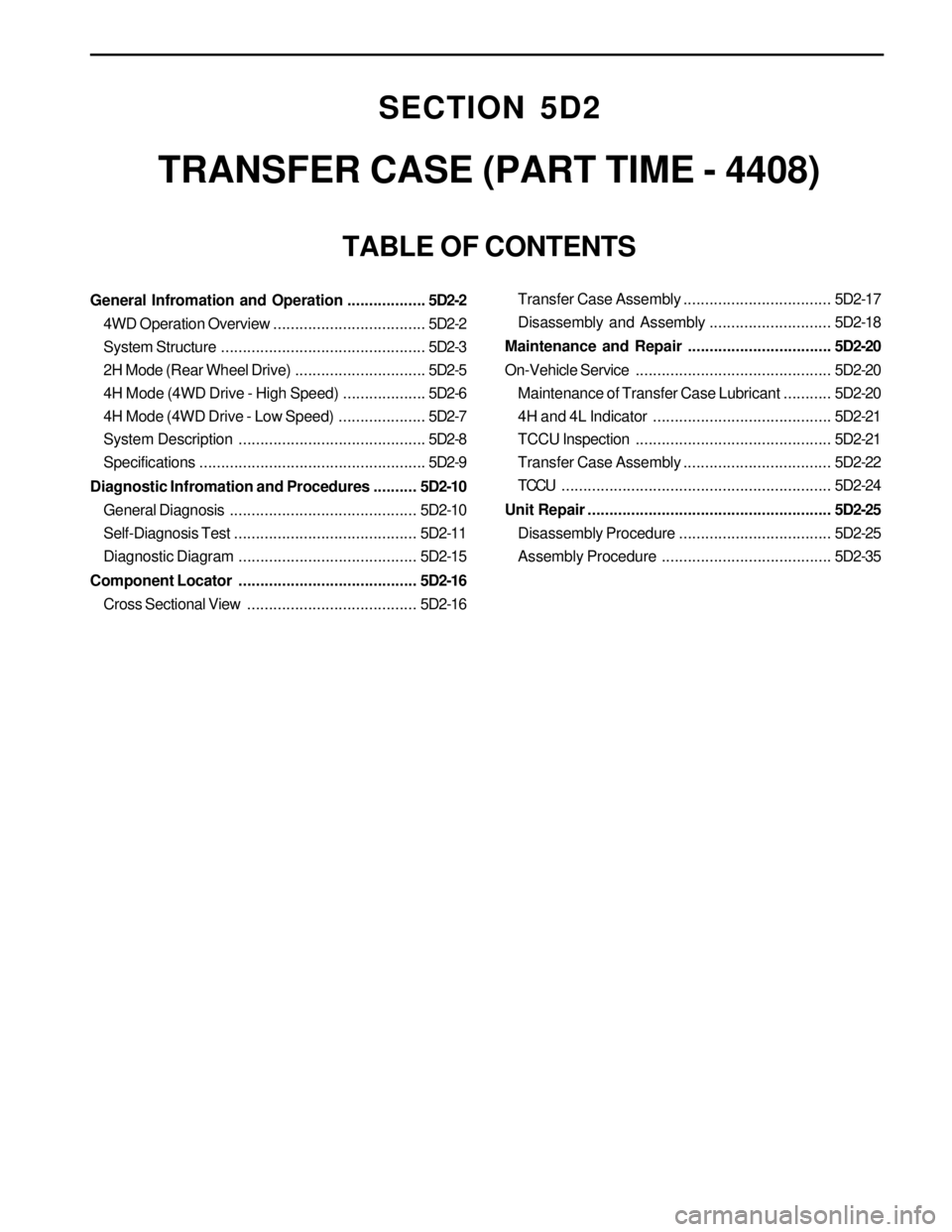
SECTION 5D2
TRANSFER CASE (PART TIME - 4408)
TABLE OF CONTENTS
General Infromation and Operation..................5D2-2
4WD Operation Overview...................................5D2-2
System Structure...............................................5D2-3
2H Mode (Rear Wheel Drive)..............................5D2-5
4H Mode (4WD Drive - High Speed)...................5D2-6
4H Mode (4WD Drive - Low Speed)....................5D2-7
System Description...........................................5D2-8
Specifications....................................................5D2-9
Diagnostic Infromation and Procedures..........5D2-10
General Diagnosis...........................................5D2-10
Self-Diagnosis Test..........................................5D2-11
Diagnostic Diagram .........................................5D2-15
Component Locator .........................................5D2-16
Cross Sectional View.......................................5D2-16Transfer Case Assembly..................................5D2-17
Disassembly and Assembly............................5D2-18
Maintenance and Repair.................................5D2-20
On-Vehicle Service.............................................5D2-20
Maintenance of Transfer Case Lubricant...........5D2-20
4H and 4L Indicator .........................................5D2-21
TCCU Inspection.............................................5D2-21
Transfer Case Assembly..................................5D2-22
TCCU..............................................................5D2-24
Unit Repair........................................................5D2-25
Disassembly Procedure...................................5D2-25
Assembly Procedure.......................................5D2-35
Page 1419 of 2053
SSANGYONG MY2002
5D2-20 TRANSFER CASE (PART TIME - 4408)
������
KAA5D220
ON-VEHICLE SERVICE
MAINTENANCE OF TRANSFER
CASE LUBRICANT
1. Oil Level Check
Clean the oil level plug and surrounding area.
Remove the oil level plug and check whether
oil is drip out or not.
Tighten the oil level plug.
Installation Notice
KAA5D230
MAINTENANCE AND REPAIR
2. Oil Change
Clean the oil level plug and surrounding area
Place a suitable container under the transfer
case.
Remove the oil and tighten the drain plug.
Installation Notice
Fill the oil through the oil level plug until oil
begins to drip out.
Tighten the oil level plug.
3. Cautions for oil level check and plugs tightening
Do not use an impact wrench to remove or
tighten the oil level plug or drain plug since this
will damage the threads in the transfer case.
Tightening Torque4 - 6 Nm
(35 - 53 lb-in)
Tightening Torque20 - 30 Nm
(15 - 22 lb-ft)
Page 1443 of 2053

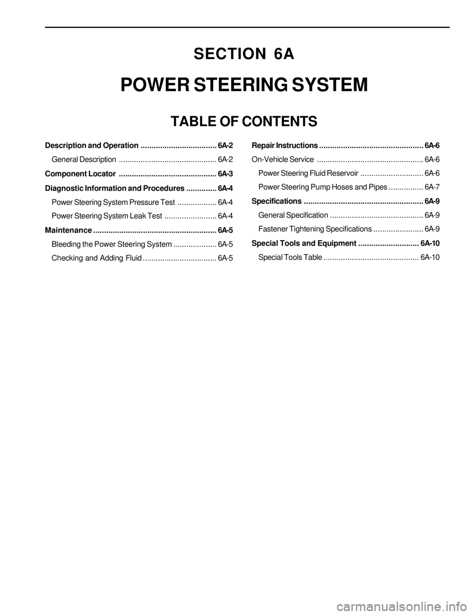
SECTION 6A
POWER STEERING SYSTEM
TABLE OF CONTENTS
Description and Operation...................................6A-2
General Description.............................................6A-2
Component Locator.............................................6A-3
Diagnostic Information and Procedures..............6A-4
Power Steering System Pressure Test..................6A-4
Power Steering System Leak Test........................6A-4
Maintenance .........................................................6A-5
Bleeding the Power Steering System....................6A-5
Checking and Adding Fluid..................................6A-5Repair Instructions................................................6A-6
On-Vehicle Service.................................................6A-6
Power Steering Fluid Reservoir.............................6A-6
Power Steering Pump Hoses and Pipes................6A-7
Specifications.......................................................6A-9
General Specification...........................................6A-9
Fastener Tightening Specifications.......................6A-9
Special Tools and Equipment............................ 6A-10
Special Tools Table............................................6A-10
Page 1447 of 2053

POWER STEERING SYSTEM 6A-5
SSANGYONG MY2002
BLEEDING THE POWER
STEERING SYSTEM
1. Disconnect the fuel line. Using a starter motor,
crank the engine and turn the steering wheel from
lock to start 5 or 6 times.
Notice: Do bleeding with engine cranking. If bleed
with idling, there can be a air contact with oil.
2. Connect the fuel feed line and start the engine at
idle speed.
3. Turn the steering wheel from lock to lock until there
is no more air in oil reservoir.
4. Connect the oil level is within specification.
5. By turning the steering wheel left to right, check
the oil level change.
Notice: If oil is not changes more than 5 mm, do
bleeding again. If oil level rises suddenly when
stopped engine, again.
MAINTENANCE
CHECKING AND ADDING FLUID
Notice: When adding fluid or making a complete fluid
change, always use DEXRON. - II power steering fluid.
Failure to use the proper fluid will cause hose and seal
damage and fluid leaks.
1. The power steering fluid level is indicated by marks
on a fluid level indicator on the fluid reservoir cap.
2. If the fluid is warmed up to 66 °C (150 °F), the fluid
level should be between the MAX and MIN marks.
Add fluid as needed.
3. If the fluid is cool, 21 °C (70 °F), the fluid level should
be at the MIN mark. Add fluid as needed.