Page 675 of 2053
1B3 -- 126 OM600 ENGINE MECHANICAL
D AEW OO M Y_2000
15. Hang the cylinder head (1) to the lifting device and
heat in a water tank to approx. 80_C.
16. Cool down new valve seat ring (2) into the cooling
box with liquidnitrogen.
Notice
Do not touch the cooled valve seat rings with hand.
Super Cooling Box 345 589 00 63 00
17. Drive in new valve seat ring (2) with a proper wood-
en drift.
18. Install the valve guide (3) with a proper drift and as-
sembling tool.
Notice
Thevalveguidemustbedriveninfromthecylinder
head cover.
Drift (Intake) 8mm
Drift (Exhaust) 9mm
19. Machine the valve seats.
Page 696 of 2053
OM600 ENGINE MECHANICAL 1B3 -- 147
D AEW OO M Y_2000
TIMING CHAIN
Preceding Work : Removal of glow plug
Removal of chain tensioner
Removal of cooling fan
Removal of cylinder head cover
1 Chain Link
2 Timing Chain
3 Camshaft Sprocket
4 Outer Plate
Page 701 of 2053
1B3 -- 152 OM600 ENGINE MECHANICAL
D AEW OO M Y_2000
CYLINDER HEAD GUIDE RAIL
Preceding Work : Removal of the cooling fan
Removal of poly V-- belt
Removal of chain tensioner
1 Cylinder Head Cover
2 Bolt 10N∙m (89 lb-in) .....................
3 Gasket Replace..........................
4 Camshaft Sprocket
5 Washer
6 12-- Sided Bolt (M11)
Inspect, 25N∙m (18 lb-ft)+90_ ..............
7 Tensioning Lever
8 Bolt 23N∙m (17 lb-ft) ......................9 Bearing Pin Sealing Compound.............
10 Guide Rail
11 Bearing Pin
12 Guide Pulley
13 Socket Bolt 23N∙m (17 lb-ft) ................
14 Closing Cover
15 Spring
16 Timing Chain
Page 732 of 2053
OM600 ENGINE MECHANICAL 1B3 -- 183
D AEW OO M Y_2000
OIL GALLERY STEEL BALL
Preceding Work : Removal of cooling fan
Removal of the water pump housing
Removal of the flywheel and driven plate
1 Steel Ballφ15mm .........................2 Screw Plug Loctite 241, 50N∙m .............
Notice
The screw plug (2) has to be installed as a repair
solution if the steel ball (1) is leaking.
Page 737 of 2053

D AEW OO M Y_2000
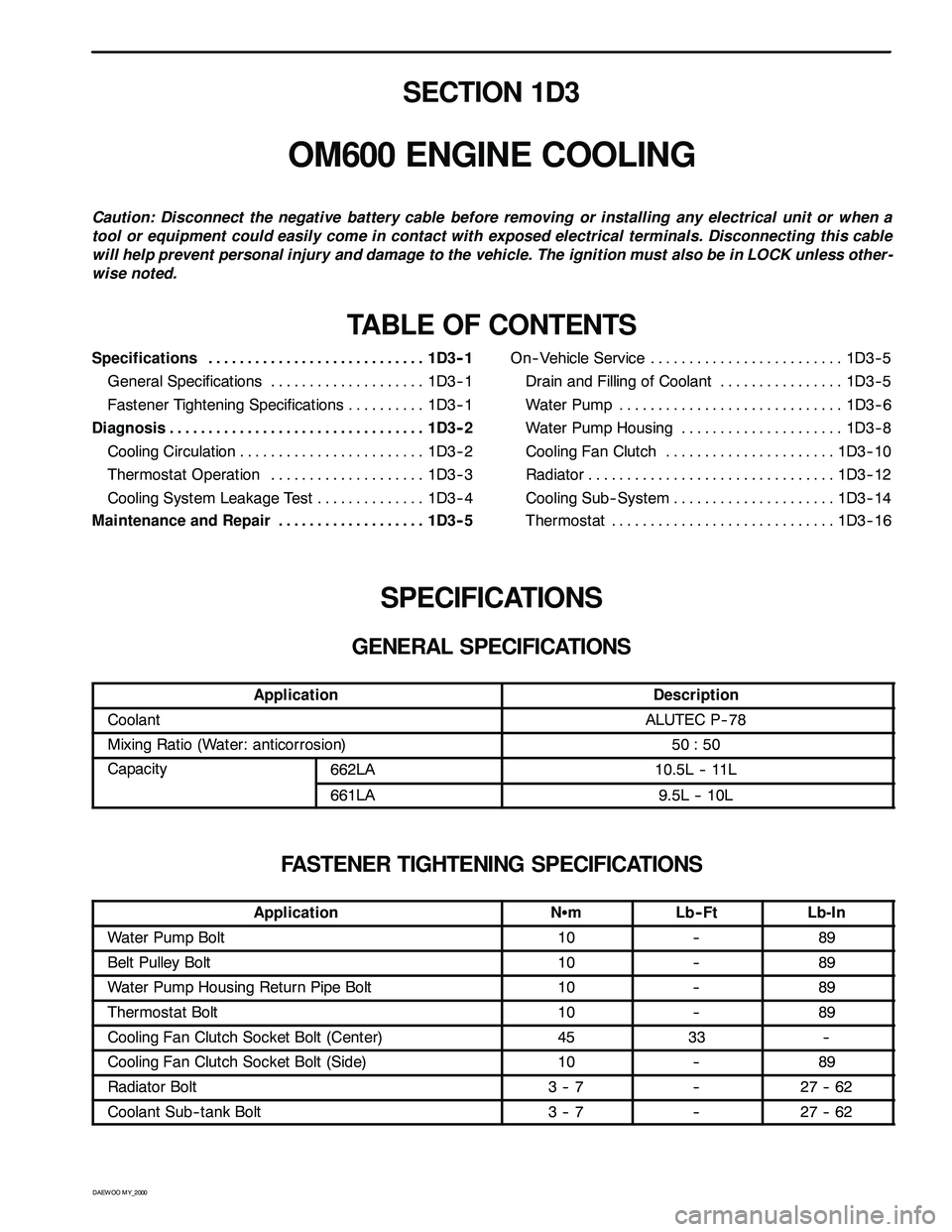
SECTION 1D3
OM600 ENGINE COOLING
Caution: Disconnect the negative battery cable before removing or installing any electrical unit or when a
tool or equipment could easily come in contact with exposed electrical terminals. Disconnecting this cable
will help prevent personal injury and damage to the vehicle. The ignition must also be in LOCK unless other -
wise noted.
TABLE OF CONTENTS
Specifications 1D3 -- 1............................
General Specifications 1D3-- 1....................
Fastener Tightening Specifications 1D3 -- 1..........
Diagnosis 1D3 -- 2.................................
Cooling Circulation 1D3 -- 2........................
Thermostat Operation 1D3 -- 3....................
Cooling System Leakage Test 1D3-- 4..............
Maintenance and Repair 1D3 -- 5...................On-- Vehicle Service 1D3-- 5.........................
Drain and Filling of Coolant 1D3 -- 5................
Wat er Pum p 1D3 -- 6.............................
Water Pump Housing 1D3-- 8.....................
Cooling Fan Clutch 1D3 -- 10......................
Radiator 1D3-- 12................................
Cooling Sub-- System 1D3-- 14.....................
Thermostat 1D3 -- 16.............................
SPECIFICATIONS
GENERAL SPECIFICATIONS
ApplicationDescription
CoolantALUTEC P-- 78
Mixing Ratio (Water: anticorrosion)50 : 50
Capacity662LA10.5L -- 11Lpy
661LA9.5L -- 10L
FASTENER TIGHTENING SPECIFICATIONS
ApplicationNSmLb-- FtLb-In
Water Pump Bolt10--89
Belt Pulley Bolt10--89
Water Pump Housing Return Pipe Bolt10--89
Thermostat Bolt10--89
Cooling Fan Clutch Socket Bolt (Center)4533--
Cooling Fan Clutch Socket Bolt (Side)10--89
Radiator Bolt3--7--27 -- 62
Coolant Sub-- tank Bolt3--7--27 -- 62
Page 738 of 2053
1D3 -- 2 OM600 ENGINE COOLING
D AEW OO M Y_2000
DIAGNOSIS
COOLING CIRCULATION
A Thermostat
B Radiator
D From Heater
EHoseG Deaeration Line
HReservoir
Page 739 of 2053
1D3 -- 4 OM600 ENGINE COOLING
D AEW OO M Y_2000
COOLING SYSTEM LEAKAGE TEST
Tools Required
124589152100Tester
Test
1. Loosen the pressure cap by 1 notch and remove the
cap after.
Notice
Do not remove radiator cap when coolant is above
90°C.
2. Add the coolant to the arrow mark of coolant reser-
voir.
3. Connect the special tool to the injector of reservoir
and apply 1.4bar pressure.
Tester 124 589 15 21 00
4. If the pressure on the tester drops, check the hose,
pipe and leakage and, replace or retighten.
Page 740 of 2053
OM600 ENGINE COOLING 1D3 -- 5
D AEW OO M Y_2000
MAINTENANCE AND REPAIR
ON -- VEHICLE SERVICE
DRAIN AND FILLING OF COOLANT
Preceding Work : Removal of skid plate
Drain / Filling
1. Loosen the pressure cap of reservoir by 1 notch and
remove pressure and then loosen the cap.
Notice
Do not remove radiator cap when coolant is above
90°C.
2. Open the drain plug and drain the coolant.
Notice
Collect the coolant by using the proper bottle.
3. Remove the drain plug(1) and seal(2) of cylinder
block and drain the coolant.
4. Replace the seal to new one and tighten the drain
plug.
Installation Notice
Tightening Torque30 N∙m (22 lb-ft)
5. Tighten the drain plug of the lower radiator.
6. Fill the coolant through coolant reservoir -- tank.
Notice
DA proportion of 50% by volume of water / anticor-
rosion must be ensured.
7. After engine is running at idle speed, check the level
of coolant. If necessary, add enough specified cool-
ant.