Page 1723 of 4133
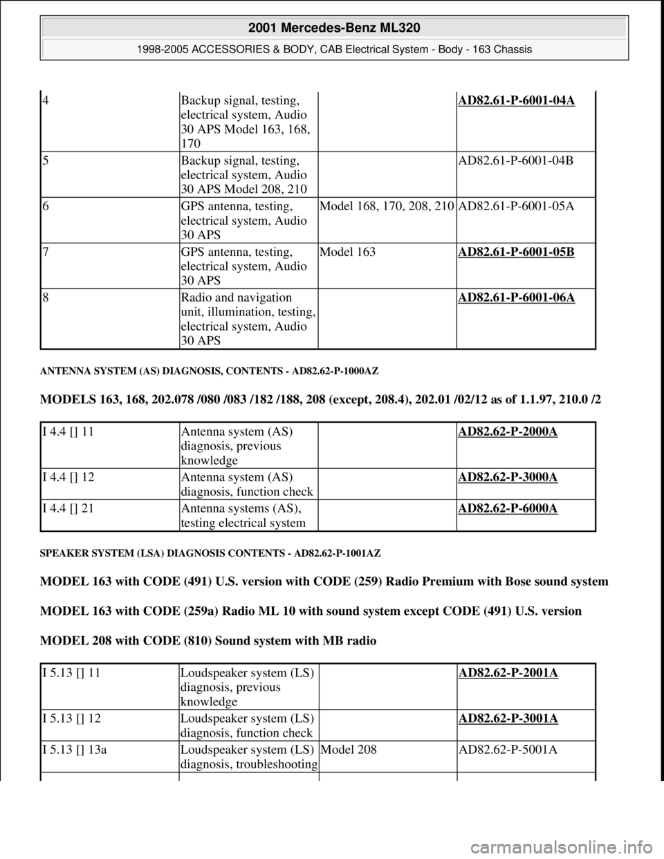
ANTENNA SYSTEM (AS) DIAGNOSIS, CONTENTS - AD82.62-P-1000AZ
MODELS 163, 168, 202.078 /080 /083 /182 /188, 208 (except, 208.4), 202.01 /02/12 as of 1.1.97, 210.0 /2
SPEAKER SYSTEM (LSA) DIAGNOSIS CONTENTS - AD82.62-P-1001AZ
MODEL 163 with CODE (491) U.S. version with CODE (259) Radio Premium with Bose sound system
MODEL 163 with CODE (259a) Radio ML 10 with sound system except CODE (491) U.S. version
MODEL 208 with CODE (810) Sound system with MB radio
4Backup signal, testing,
electrical system, Audio
30 APS Model 163, 168,
170 AD82.61-P-6001-04A
5Backup signal, testing,
electrical system, Audio
30 APS Model 208, 210 AD82.61-P-6001-04B
6GPS antenna, testing,
electrical system, Audio
30 APSModel 168, 170, 208, 210AD82.61-P-6001-05A
7GPS antenna, testing,
electrical system, Audio
30 APSModel 163AD82.61-P-6001-05B
8Radio and navigation
unit, illumination, testing,
electrical system, Audio
30 APS AD82.61-P-6001-06A
I 4.4 [] 11Antenna system (AS)
diagnosis, previous
knowledge AD82.62-P-2000A
I 4.4 [] 12Antenna system (AS)
diagnosis, function check AD82.62-P-3000A
I 4.4 [] 21Antenna systems (AS),
testing electrical system AD82.62-P-6000A
I 5.13 [] 11Loudspeaker system (LS)
diagnosis, previous
knowledge AD82.62-P-2001A
I 5.13 [] 12Loudspeaker system (LS)
diagnosis, function check AD82.62-P-3001A
I 5.13 [] 13aLoudspeaker system (LS)
diagnosis, troubleshootingModel 208AD82.62-P-5001A
2001 Mercedes-Benz ML320
1998-2005 ACCESSORIES & BODY, CAB Electrical System - Body - 163 Chassis
me
Saturday, October 02, 2010 3:30:08 PMPage 228 © 2006 Mitchell Repair Information Company, LLC.
Page 1782 of 4133
starts flashing again. In this state the code number can be written over as frequently as desired. A
correction can be made only by entering the complete code number again.
4. Confirm code number:
Press TUNE, AUTO/SEEK or SC button. The radio automatically switches on and indicates the radio
station or frequency stored with station button 1.
5. If an incorrect code number is entered and confirmed, the word "CODE" appears again on the display. If
an incorrect code is entered three times the word "WAIT" appears on the display and the radio locks up
for approx. 10 min. If the code is entered incorrectly three times again the radio locks up again for 10
min. Three more incorrect entries (a total of 9 incorrect attempts) increase the lock-up time to 60 min.
Another three incorrect entries lock up the radio for another 60 min.
The waiting time runs only when the radio is switched on.
CODING RADIO - AR82.60-P-7502-01GH
1. If the power supply to the radio is interrupted the radio will not operate when reconnected. After
switching on the ignition the word "CODE" appears on the radio display.
2. The code number for this radio is given on the included code card.
3. Enter the code number with the station buttons, e.g. number 1 = station button 1..
4. After entering the first digit the word "CODE" disappears and the number entered is displayed followed
by four dashes. Enter the next numbers with the corresponding station buttons. After entering the five
digit code number compare the code number with the number on the display. At this point the code
number can be written over as frequently as necessary for correction. If the wrong code number has been
entered, enter the entire code number again.
5. Confirm entry of correct code number with " < " or " > " button.
6. If the wrong code number has been entered and confirmed the word "CODE" appears again on the display
and the code must be entered again.
7. After entering the code incorrectly three times the word "WAIT" appears on the display and the radio is
disabled for approx. 10 minutes. After entering the incorrect code three times again the radio is disabled
for approx. 60 minutes.
The disable time runs down only with the radio switched off.
REMOVE/INSTALL RADIO - AR82.60-P-7502EA
MODEL 129 with single-block unit, 2nd generation two-component unit control element and MB radios
MODEL 163 with CODE (257) Hi-Line radio with CODE (259) Premium radio with Bose sound system
with CODE (352) COMAND operating and display system with CODE (353) Audio 30 APS with CODE
(357) Navigation system - additional unit with CODE (522) Modular control system (MCS) radio USA
with CODE (750) MB Audio 30 RDS radio with CODE (752) Becker Mexico 2000 radio with traffic news
decoder with CODE (753) MB Audio 30 RDS radio with CODE (756) MB Audio 10 RDS radio with CD
compartment
2001 Mercedes-Benz ML320
1998-2005 ACCESSORIES & BODY, CAB Electrical System - Body - 163 Chassis
me
Saturday, October 02, 2010 3:30:09 PMPage 287 © 2006 Mitchell Repair Information Company, LLC.
Page 1786 of 4133
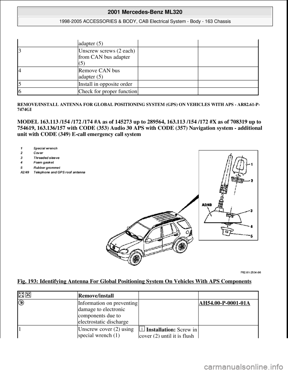
REMOVE/INSTALL ANTENNA FOR GLOBAL POSITIONING SYSTEM (GPS) ON VEHICLES WITH APS - AR82.61-P-
7474GI
MODEL 163.113 /154 /172 /174 #A as of 145273 up to 289564, 163.113 /154 /172 #X as of 708319 up to
754619, 163.136/157 with CODE (353) Audio 30 APS with CODE (357) Navigation system - additional
unit with CODE (349) E-call emergency call system
Fig. 193: Identifying Antenna For Global Positioning System On Vehicles With APS Components
adapter (5)
3Unscrew screws (2 each)
from CAN bus adapter
(5)
4Remove CAN bus
adapter (5)
5Install in opposite order
6Check for proper function
Remove/install
Information on preventing
damage to electronic
components due to
electrostatic discharge AH54.00-P-0001-01A
1Unscrew cover (2) using
special wrench (1) Installation:Screw in
cover (2) until it is flush
2001 Mercedes-Benz ML320
1998-2005 ACCESSORIES & BODY, CAB Electrical System - Body - 163 Chassis
me
Saturday, October 02, 2010 3:30:09 PMPage 291 © 2006 Mitchell Repair Information Company, LLC.
Page 1796 of 4133
REPLACE FIBER OPTICAL CA BLE (D2B) BETWEEN RADIO AND SOUND AMPLIFIER (AFTER TESTING) - AR82.62-P-
8350GH
MODEL 163.113 /154 /174 #A as of 289565, 163.113 #X as of 754620, 163.128 /157 /175 with CODE (810)
Sound system
Fig. 203: Identifying Sound Amplif ier, Radio And Navigation Unit
Fig. 204: Identifying ETC Control Modul e And Exchange D2B Wiring Harness
amplifier (A2/18) with
bracket (5)
6Install in the reverse order
7Perform function check
2001 Mercedes-Benz ML320
1998-2005 ACCESSORIES & BODY, CAB Electr ical System - Body - 163 Chassis
me
Saturday, October 02, 2010 3:30:10 PMPage 301 © 2006 Mitchell Repair Information Company, LLC.
Page 1815 of 4133
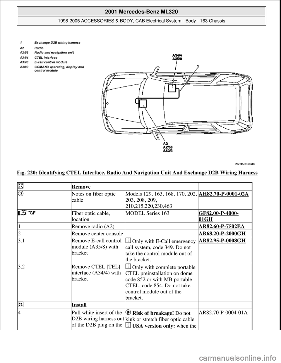
Fig. 220: Identifying CTEL Interface, Radio And Navigation Unit And Exchange D2B Wiring Harness
Remove
Notes on fiber optic
cableModels 129, 163, 168, 170, 202,
203, 208, 209,
210,215,220,230,463AH82.70-P-0001-02A
Fiber optic cable,
locationMODEL Series 163GF82.00-P-4000-
01GH
1Remove radio (A2) AR82.60-P-7502EA
2Remove center console AR68.20-P-2000GH
3.1Remove E-call control
module (A35/8) with
bracket Only with E-Call emergency
call system, code 349. Do not
take the control module out of
the bracket.AR82.95-P-0008GH
3.2Remove CTEL [TEL]
interface (A34/4) with
bracket Only with complete portable
CTEL preinstallation on dome
code 852 or with MB portable
CTEL, code 854. Do not take
control module out of the
bracket.
Install
4Pull white insert of the
D2B wiring harness out
of the D2B plug on the Risk of breakage! Do not
kink or stretch fiber optic cable
USA version only: when the AR82.70-P-0004-01A
2001 Mercedes-Benz ML320
1998-2005 ACCESSORIES & BODY, CAB Electrical System - Body - 163 Chassis
me
Saturday, October 02, 2010 3:30:10 PMPage 320 © 2006 Mitchell Repair Information Company, LLC.
Page 1823 of 4133
3. Connect adapter wiring harness (4) to standard wiring harness and radio and navigation operating unit
(A2/29) with radio mating connector (7).
Fig. 228: Identifying Adapter Wiring Harness, Radio And Navigation Operating Unit And Radio
Mating Connector
4. Connect black 10-pin connector (C) to radio and navigation operating unit (A2/29).
5. Connect GPS antenna lead (41) as shown in figure.
Fig. 229: Identifying 10
-Pin Connector, Radio And Navigation Operating Unit, GPS Antenna Lead
And Green Back-Up Lamp Signal Lead
6. Route tie-out to CAN bus adapter (5) from adapter wiring harness (5) to center tunnel at rear.
2001 Mercedes-Benz ML320
1998-2005 ACCESSORIES & BODY, CAB Electrical System - Body - 163 Chassis
me
Saturday, October 02, 2010 3:30:10 PMPage 328 © 2006 Mitchell Repair Information Company, LLC.
Page 1825 of 4133
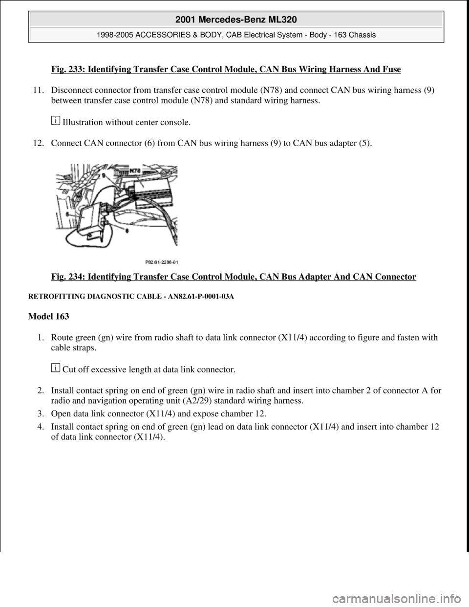
Fig. 233: Identifying Transfer Case Control Module, CAN Bus Wiring Harness And Fuse
11. Disconnect connector from transfer case control module (N78) and connect CAN bus wiring harness (9)
between transfer case control module (N78) and standard wiring harness.
Illustration without center console.
12. Connect CAN connector (6) from CAN bus wiring harness (9) to CAN bus adapter (5).
Fig. 234: Identifying Transfer Case Control Module, CAN Bus Adapter And CAN Connector
RETROFITTING DIAGNOSTIC CABLE - AN82.61-P-0001-03A
Model 163
1. Route green (gn) wire from radio shaft to data link connector (X11/4) according to figure and fasten with
cable straps.
Cut off excessive length at data link connector.
2. Install contact spring on end of green (gn) wire in radio shaft and insert into chamber 2 of connector A for
radio and navigation operating unit (A2/29) standard wiring harness.
3. Open data link connector (X11/4) and expose chamber 12.
4. Install contact spring on end of green (gn) lead on data link connector (X11/4) and insert into chamber 12
of data link connector (X11/4).
2001 Mercedes-Benz ML320
1998-2005 ACCESSORIES & BODY, CAB Electrical System - Body - 163 Chassis
me
Saturday, October 02, 2010 3:30:10 PMPage 330 © 2006 Mitchell Repair Information Company, LLC.
Page 1826 of 4133
Fig. 235: Identifying Retrofitting Diagnostic Cable
If a lead is already present in chamber 12 connect it to the green (gn) lead using a solder connector.
RETROFIT NAVIGATION SYSTEM AUDIO 30 APS - AN82.61-P-0001H
MODEL 163 up to 30.6.99 except CODE (819) 6-disk CD changer in trunk
MODEL 163 as of 1.7.99 in combination with CD changer with D2B fiber optic cable system
System illustration with GPS and telephone roof antenna
2001 Mercedes-Benz ML320
1998-2005 ACCESSORIES & BODY, CAB Electrical System - Body - 163 Chassis
me
Saturday, October 02, 2010 3:30:10 PMPage 331 © 2006 Mitchell Repair Information Company, LLC.