Page 2547 of 4133
Fig. 43: Identifying Brake Caliper Dust Shield And Supporting Joint
Wheel location, hub
Remove
1Remove steering knuckle AR33.25-P-
0400GH
2Detach and rotate brake caliper dust shield
3Press supporting joint (7) out of steering knuckle (5) AR33.20-P-0440-
01GH
Install
4Pull in supporting joint (7) with locking slotted
round nut until it abuts
Replace locking
slotted nut.AR33.20-P-0440-
01GH
*BA33.20-P-1003-
01D
Claw-type wrenchFig. 38
5Attach brake caliper dust shield
6Install steering knuckle AR33.25-P-
0400GH
NumberDesignationModel Series 163
BA33.20-P-1003-01DLocking slotted nut, supporting joint to steering knuckleNM300
2001 Mercedes-Benz ML320
1998-2005 DRIVELINE/AXLES Front Axle - 163 Chassis
me
Saturday, October 02, 2010 3:38:22 PMPage 28 © 2006 Mitchell Repair Information Company, LLC.
Page 2548 of 4133
Fig. 44: Identifying Prong Wrench (385 589 00 07 00)
PRESSING OUT AND ATTACHING FOLLOWER JOINT AT STEERING KNUCKLE - AR33.20-P-0500-01GH
Wheel location, hub
Fig. 45: Identifying Thrust Piece (129 589 10 63 00)
Fig. 46: Identifying Support (163 589 01 43 00)
NumberDesignationModel
163
BA33.20-P-1001-
01DSelf-locking nut, upper transverse control arm follower joint to
steering knuckleNM50
2001 Mercedes-Benz ML320
1998-2005 DRIVELINE/AXLES Front Axle - 163 Chassis
me
Saturday, October 02, 2010 3:38:22 PMPage 29 © 2006 Mitchell Repair Information Company, LLC.
Page 2550 of 4133
Fig. 49: Identifying Upper Wishbone Components
Remove/install
Notes on self-locking nuts and
boltsAll modelsAH00.00-N-
0001-01A
1
Remove front wheels
Remove, remount front road
wheels, rotate as necessaryAP40.10-P-
4050GH
2Remove shock absorber AR32.25-P-
0105GH
3Detach brake line bracket from
steering knuckle
4Use extractor to remove guide
joint from upper control arm (6)
AR33.20-P-
0500-01GH
*BA33.20-P-
1001-01D
Thrust pieceFig. 45
SupportFig. 46
PressFig. 47
5
Secure steering knuckle to shock
absorber with a wire to prevent it
from tilting down To avoid leaks within the hydraulic brake
system and open circuits in the electrical
wiring, never tug on the brake lines or the
electrical wiring.
2001 Mercedes-Benz ML320
1998-2005 DRIVELINE/AXLES Front Axle - 163 Chassis
me
Saturday, October 02, 2010 3:38:22 PMPage 31 © 2006 Mitchell Repair Information Company, LLC.
Page 2551 of 4133
Wheel location, hub
Fig. 50: Identifying Press (163 589 03 43 00)
Fig. 51: Identifying Support (163 589 01 43 00)
6Detach upper transverse control
arm (6) from vehicle frame
Installation: Gently tighten the new nuts,
continuing until they seat. Wait until the
vehicle is resting on it s road wheels before
tightening the bolts.
*BA33.20-P-
1006-01D
7Install in the reverse order
8Perform chassis alignment check AR40.20-P-
0200GH
NumberDesignationModel Series
163
BA33.20-P-1001-
01DSelf-locking nut, upper wishbone follower joint to steering
knuckleNM50
BA33.20-P-1006-
01DBolt, upper wishbone to frameNM120
2001 Mercedes-Benz ML320
1998-2005 DRIVELINE/AXLES Front Axle - 163 Chassis
me
Saturday, October 02, 2010 3:38:22 PMPage 32 © 2006 Mitchell Repair Information Company, LLC.
Page 2555 of 4133

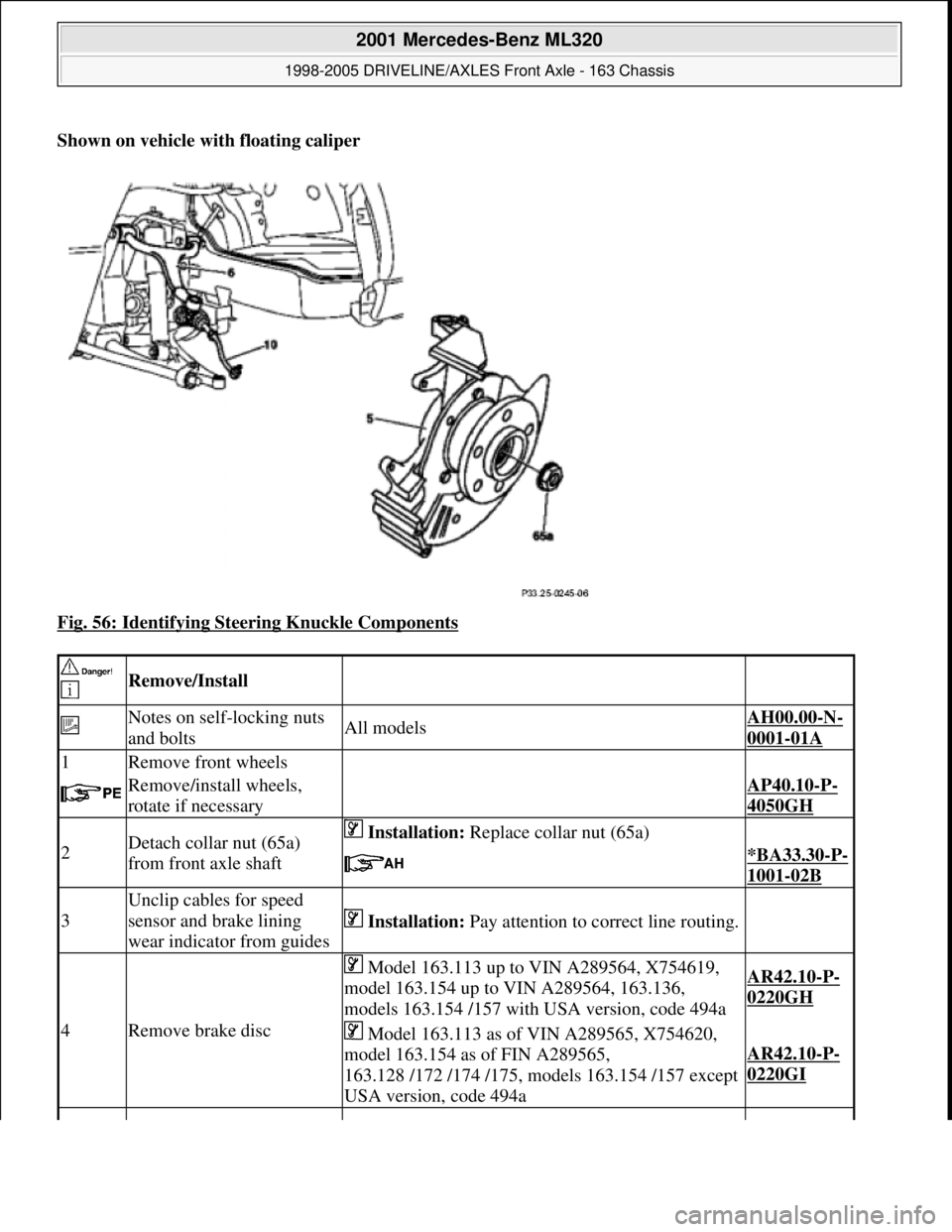
Shown on vehicle with floating caliper
Fig. 56: Identifying Steering Knuckle Components
Remove/Install
Notes on self-locking nuts
and boltsAll modelsAH00.00-N-
0001-01A
1Remove front wheels
Remove/install wheels,
rotate if necessaryAP40.10-P-
4050GH
2Detach collar nut (65a)
from front axle shaft Installation: Replace collar nut (65a)
*BA33.30-P-
1001-02B
3
Unclip cables for speed
sensor and brake lining
wear indicator from guides
Installation: Pay attention to correct line routing.
4Remove brake disc
Model 163.113 up to VIN A289564, X754619,
model 163.154 up to VIN A289564, 163.136,
models 163.154 /157 with USA version, code 494aAR42.10-P-
0220GH
Model 163.113 as of VIN A289565, X754620,
model 163.154 as of FIN A289565,
163.128 /172 /174 /175, models 163.154 /157 except
USA version, code 494a
AR42.10-P-
0220GI
2001 Mercedes-Benz ML320
1998-2005 DRIVELINE/AXLES Front Axle - 163 Chassis
me
Saturday, October 02, 2010 3:38:22 PMPage 36 © 2006 Mitchell Repair Information Company, LLC.
Page 2556 of 4133

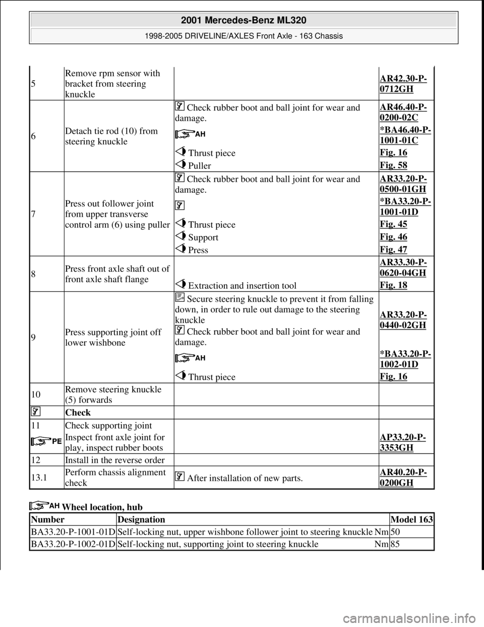
Wheel location, hub
5
Remove rpm sensor with
bracket from steering
knuckle
AR42.30-P-
0712GH
6Detach tie rod (10) from
steering knuckle
Check rubber boot and ball joint for wear and
damage.AR46.40-P-
0200-02C
*BA46.40-P-
1001-01C
Thrust pieceFig. 16
PullerFig. 58
7
Press out follower joint
from upper transverse
control arm (6) using puller
Check rubber boot and ball joint for wear and
damage.AR33.20-P-
0500-01GH
*BA33.20-P-
1001-01D
Thrust pieceFig. 45
SupportFig. 46
PressFig. 47
8Press front axle shaft out of
front axle shaft flange AR33.30-P-
0620-04GH
Extraction and insertion toolFig. 18
9Press supporting joint off
lower wishbone
Secure steering knuckle to prevent it from falling
down, in order to rule out damage to the steering
knuckle
Check rubber boot and ball joint for wear and
damage.
AR33.20-P-
0440-02GH
*BA33.20-P-
1002-01D
Thrust pieceFig. 16
10Remove steering knuckle
(5) forwards
Check
11Check supporting joint
Inspect front axle joint for
play, inspect rubber bootsAP33.20-P-
3353GH
12Install in the reverse order
13.1Perform chassis alignment
check After installation of new parts.AR40.20-P-
0200GH
NumberDesignationModel 163
BA33.20-P-1001-01DSelf-locking nut, upper wishbone follower joint to steering knuckleNm50
BA33.20-P-1002-01DSelf-locking nut, supporting joint to steering knuckleNm85
2001 Mercedes-Benz ML320
1998-2005 DRIVELINE/AXLES Front Axle - 163 Chassis
me
Saturday, October 02, 2010 3:38:22 PMPage 37 © 2006 Mitchell Repair Information Company, LLC.
Page 2562 of 4133

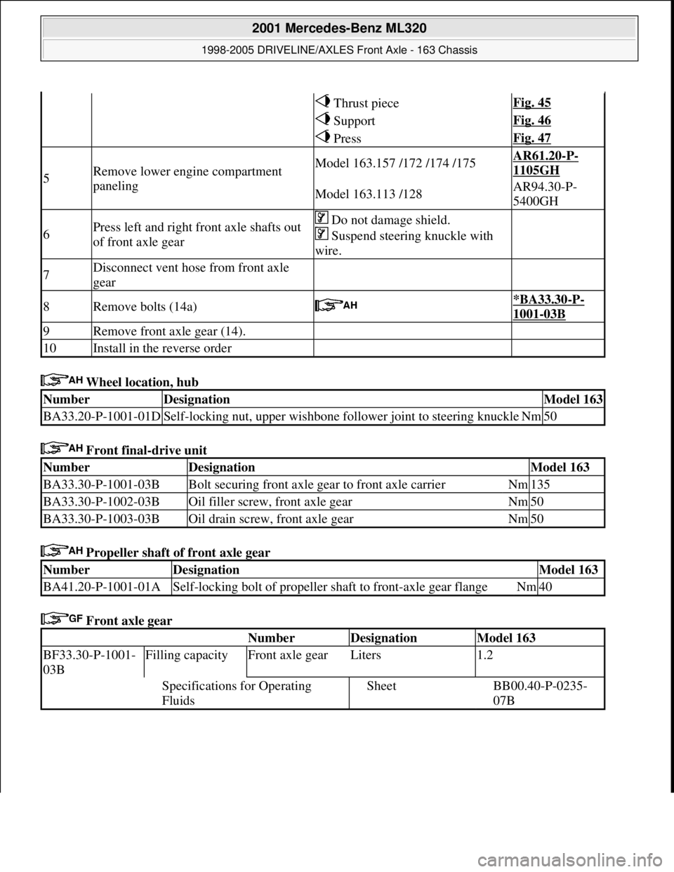
Wheel location, hub
Front final-drive unit
Propeller shaft of front axle gear
Front axle gear
Thrust pieceFig. 45
SupportFig. 46
PressFig. 47
5Remove lower engine compartment
panelingModel 163.157 /172 /174 /175AR61.20-P-
1105GH
Model 163.113 /128AR94.30-P-
5400GH
6Press left and right front axle shafts out
of front axle gear Do not damage shield.
Suspend steering knuckle with
wire.
7Disconnect vent hose from front axle
gear
8Remove bolts (14a) *BA33.30-P-
1001-03B
9Remove front axle gear (14).
10Install in the reverse order
NumberDesignationModel 163
BA33.20-P-1001-01DSelf-locking nut, upper wishbone follower joint to steering knuckleNm50
NumberDesignationModel 163
BA33.30-P-1001-03BBolt securing front axle gear to front axle carrierNm135
BA33.30-P-1002-03BOil filler screw, front axle gearNm50
BA33.30-P-1003-03BOil drain screw, front axle gearNm50
NumberDesignationModel 163
BA41.20-P-1001-01ASelf-locking bolt of propeller shaft to front-axle gear flangeNm40
Number Designation Model 163
BF33.30-P-1001-
03BFilling capacityFront axle gearLiters1.2
Specifications for Operating
FluidsSheetBB00.40-P-0235-
07B
2001 Mercedes-Benz ML320
1998-2005 DRIVELINE/AXLES Front Axle - 163 Chassis
me
Saturday, October 02, 2010 3:38:22 PMPage 43 © 2006 Mitchell Repair Information Company, LLC.
Page 2568 of 4133
Wheel location, hub
Front axle gear
Fig. 82: Identifying Thrust Piece (129 589 10 63 00)
Fig. 83: Identifying Base (163 589 01 43 00)
4Lever front axle shaft out of
front axle transmission Do not damage shield.
5Press out radial shaft sealing
ring (14e) using a suitable tool Installation: Drive in radial shaft seal using
drift (094). Install new radial shaft seal and coat
lip with universal hypoid gear oil.
Universal hypoid gear oils
(SAE 85 W-90) BB00.40-P-
0235-07A
DriftFig. 85
6Install in the reverse order
NumberDesignationModel 163
BA33.20-P-1001-01DSelf-locking nut, upper wishbone foll ower joint to steering knuckleNm50
NumberDesignationModel 163
BF33.30-P-1001-
03BFilling capacityFront axle gearLiters1.2
Specifications for
Operating FluidsSheetBB00.40-P-0235-
07B
2001 Mercedes-Benz ML320
1998-2005 DRIVELINE/AXLES Front Axle - 163 Chassis
me
Saturday, October 02, 2010 3:38:22 PMPage 49 © 2006 Mitchell Repair Information Company, LLC.