1997 MERCEDES-BENZ ML430 steering wheel
[x] Cancel search: steering wheelPage 2571 of 4133
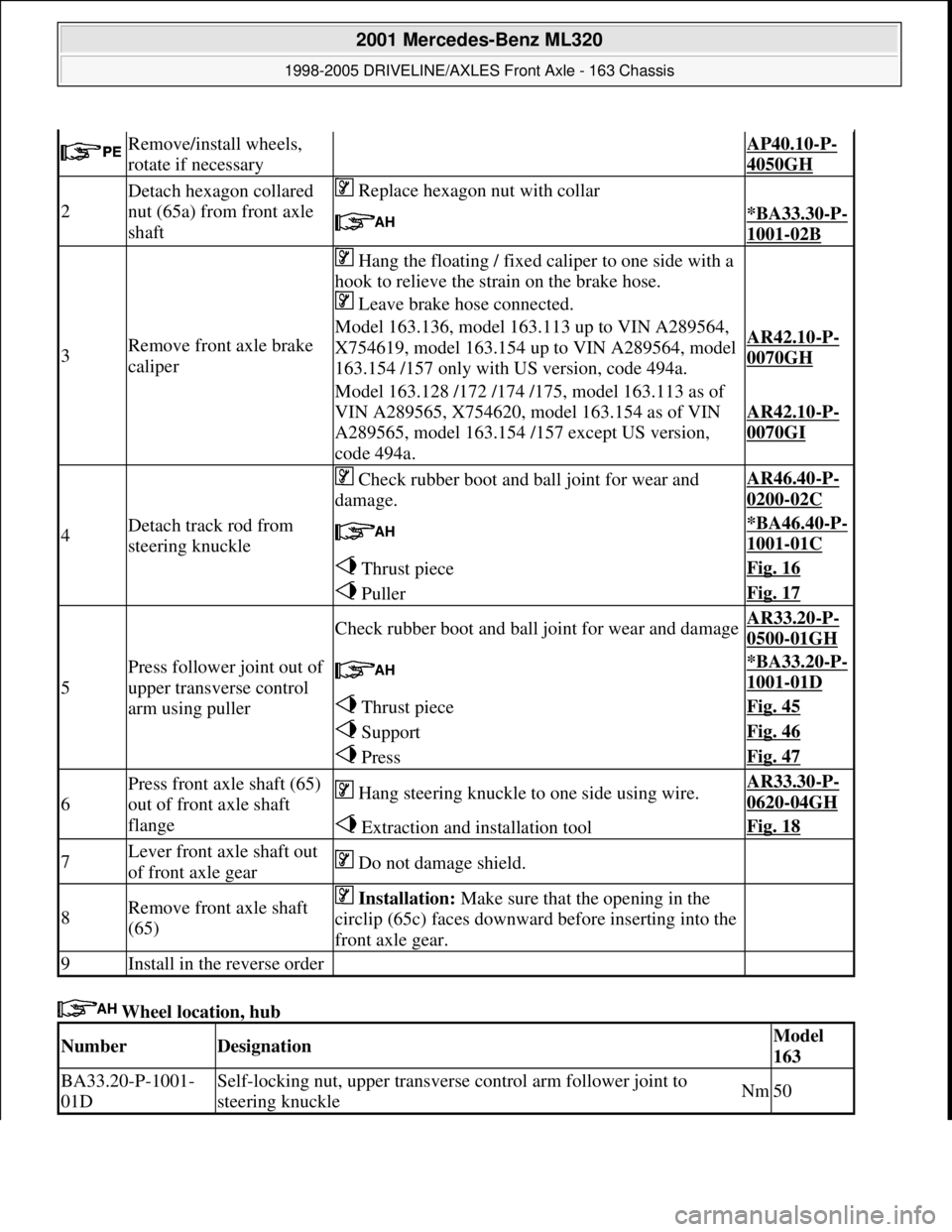
Wheel location, hub
Remove/install wheels,
rotate if necessary AP40.10-P-
4050GH
2
Detach hexagon collared
nut (65a) from front axle
shaft Replace hexagon nut with collar
*BA33.30-P-
1001-02B
3Remove front axle brake
caliper
Hang the floating / fixed caliper to one side with a
hook to relieve the strain on the brake hose.
Leave brake hose connected.
Model 163.136, model 163.113 up to VIN A289564,
X754619, model 163.154 up to VIN A289564, model
163.154 /157 only with US version, code 494a.AR42.10-P-
0070GH
Model 163.128 /172 /174 /175, model 163.113 as of
VIN A289565, X754620, model 163.154 as of VIN
A289565, model 163.154 /157 except US version,
code 494a.
AR42.10-P-
0070GI
4Detach track rod from
steering knuckle
Check rubber boot and ball joint for wear and
damage.AR46.40-P-
0200-02C
*BA46.40-P-
1001-01C
Thrust pieceFig. 16
PullerFig. 17
5
Press follower joint out of
upper transverse control
arm using puller
Check rubber boot and ball joint for wear and damageAR33.20-P-
0500-01GH
*BA33.20-P-
1001-01D
Thrust pieceFig. 45
SupportFig. 46
PressFig. 47
6
Press front axle shaft (65)
out of front axle shaft
flange Hang steering knuckle to one side using wire.AR33.30-P-
0620-04GH
Extraction and installation toolFig. 18
7Lever front axle shaft out
of front axle gear Do not damage shield.
8Remove front axle shaft
(65) Installation: Make sure that the opening in the
circlip (65c) faces downward before inserting into the
front axle gear.
9Install in the reverse order
NumberDesignationModel
163
BA33.20-P-1001-
01DSelf-locking nut, upper transverse control arm follower joint to
steering knuckleNm50
2001 Mercedes-Benz ML320
1998-2005 DRIVELINE/AXLES Front Axle - 163 Chassis
me
Saturday, October 02, 2010 3:38:22 PMPage 52 © 2006 Mitchell Repair Information Company, LLC.
Page 2580 of 4133
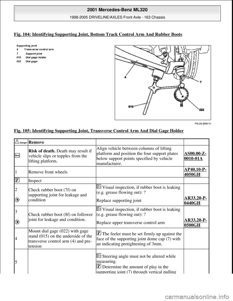
Fig. 104: Identifying Supporting Joint, Bottom Track Control Arm And Rubber Boots
Fig. 105: Identifying Supporting Joint, Transverse Control Arm And Dial Gage Holder
Remove
Risk of death. Death may result if
vehicle slips or topples from the
lifting platform.Align vehicle between columns of lifting
platform and position the four support plates
below support points specified by vehicle
manufacturer.
AS00.00-Z-
0010-01A
1Remove front wheels AP40.10-P-
4050GH
Inspect
2Check rubber boot (7f) on
supporting joint for leakage and
condition Visual inspection, if rubber boot is leaking
(e.g. grease flowing out): ?
Replace supporting jointAR33.20-P-
0440GH
3Check rubber boot (8f) on follower
joint for leakage and condition.
Visual inspection, if rubber boot is leaking
(e.g. grease flowing out): ?
Replace upper transverse control armAR33.20-P-
0500GH
4
Mount dial gage (022) with gage
stand (015) on the underside of the
transverse control arm (4) and pre-
tension The feeler must be set firmly up against the
face of the supporting joint dome cap (7) with
an indicating pretightening of 3mm.
5
Steering angle must not be altered while
measuring.
Determine the amount of play in the
supporting joint (7) through vertical pulling
2001 Mercedes-Benz ML320
1998-2005 DRIVELINE/AXLES Front Axle - 163 Chassis
me
Saturday, October 02, 2010 3:38:22 PMPage 61 © 2006 Mitchell Repair Information Company, LLC.
Page 2655 of 4133
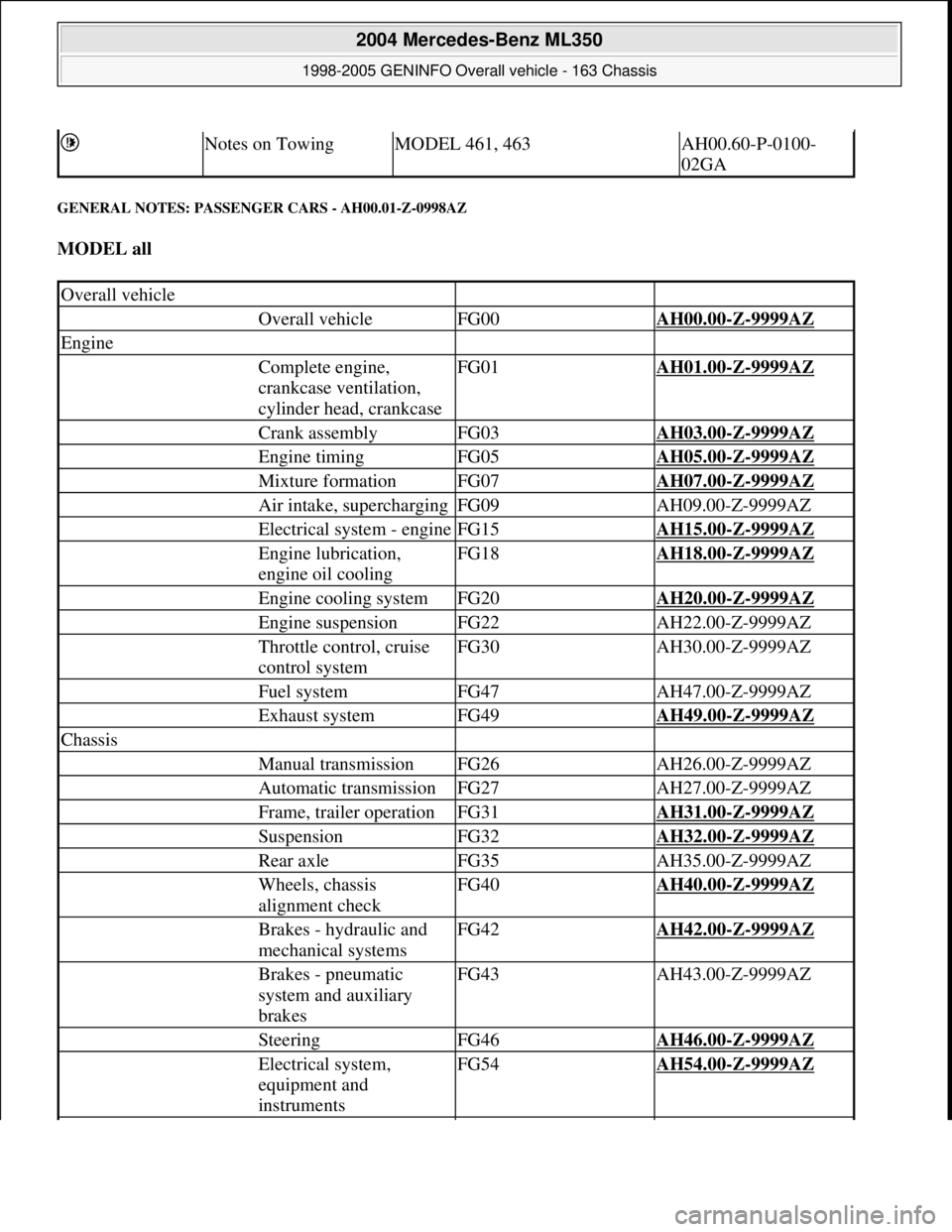
GENERAL NOTES: PASSENGER CARS - AH00.01-Z-0998AZ
MODEL all
Notes on TowingMODEL 461, 463AH00.60-P-0100-
02GA
Overall vehicle
Overall vehicleFG00AH00.00-Z-9999AZ
Engine
Complete engine,
crankcase ventilation,
cylinder head, crankcaseFG01AH01.00-Z-9999AZ
Crank assemblyFG03AH03.00-Z-9999AZ
Engine timingFG05AH05.00-Z-9999AZ
Mixture formationFG07AH07.00-Z-9999AZ
Air intake, superchargingFG09AH09.00-Z-9999AZ
Electrical system - engineFG15AH15.00-Z-9999AZ
Engine lubrication,
engine oil coolingFG18AH18.00-Z-9999AZ
Engine cooling systemFG20AH20.00-Z-9999AZ
Engine suspensionFG22AH22.00-Z-9999AZ
Throttle control, cruise
control systemFG30AH30.00-Z-9999AZ
Fuel systemFG47AH47.00-Z-9999AZ
Exhaust systemFG49AH49.00-Z-9999AZ
Chassis
Manual transmissionFG26AH26.00-Z-9999AZ
Automatic transmissionFG27AH27.00-Z-9999AZ
Frame, trailer operationFG31AH31.00-Z-9999AZ
SuspensionFG32AH32.00-Z-9999AZ
Rear axleFG35AH35.00-Z-9999AZ
Wheels, chassis
alignment checkFG40AH40.00-Z-9999AZ
Brakes - hydraulic and
mechanical systemsFG42AH42.00-Z-9999AZ
Brakes - pneumatic
system and auxiliary
brakesFG43AH43.00-Z-9999AZ
SteeringFG46AH46.00-Z-9999AZ
Electrical system,
equipment and
instrumentsFG54AH54.00-Z-9999AZ
2004 Mercedes-Benz ML350
1998-2005 GENINFO Overall vehicle - 163 Chassis
me
Saturday, October 02, 2010 3:47:44 PMPage 10 © 2006 Mitchell Repair Information Company, LLC.
Page 2892 of 4133
211, 215, 216, 219, 220, 221,
230, 240, 245, 251, 414, 461
as of 1.4.94, 463
Assessment of damage
in wiring harnessesModel 124, 126, 129, 140,
163, 164, 168, 169, 170, 171,
199, 202, 203, 208, 209, 210,
211, 215, 216, 219, 220, 221,
230, 240, 245, 251, 414, 461,
463AH00.19-P-1000-05A
Assessment of airbag
and belt tensioner units
in accident vehiclesModel 129, 202 up to 30.6.93
Model 124, 126, 140AH91.00-P-0006-01A
Assessment of airbag
and belt tensioner units
in accident vehiclesModel 129 as of 1.7.93, 163,
164, 168, 169, 170, 171, 199,
202 as of 1.7.93, 203, 208,
209, 210, 211, 215, 216, 219,
220, 221, 230, 240, 245, 251,
414, 461 as of 1.4.94, 463,
638, 901, 902, 903, 904, 905,
906, WD1, WD2, WD3, WD6,
WD7, XD1, XD2, XD3, XD4,
XD5, XD6, XD7, YD1, YD2,
YD3, YD4, YD5, YD6, YD7AH91.00-P-0006-01B
Notes regarding plug
connections AH00.19-P-1000-06A
Advantages of repairing
wiring harnesses AH00.19-P-1000-03A
Repair methods for
wiring harnesses AH00.19-P-1000-04A
Repair supplemental
restraint system (SRS)
squib wiring harnessModel 124, 129, 140, 163,
164, 168, 169, 170, 171, 202,
203, 208, 209, 210, 211, 215,
216, 219, 220, 221, 230, 240,
245, 251, 414, 461 as of
1.4.94, 463
Model 126 with code 291
Airbag for driver and front
passenger (for front passenger
only if driver airbag standard)
Model 126 with code 442
Airbag in steering wheelAR54.18-P-0600A
Repairing wiring
harnessModel 168.031 ## up to
180747 with engine 166.940
Engine wiring harness at body
side
Model 168.033 ## up to AR54.18-P-0100GF
2004 Mercedes-Benz ML350
1998-2005 GENINFO Overall vehicle - 163 Chassis
me
Saturday, October 02, 2010 3:47:48 PMPage 247 © 2006 Mitchell Repair Information Company, LLC.
Page 3149 of 4133

W4B035.
3.2 Automatic transmission fluids (ATF), sheet 236.2 , for MB passenger car and commercial vehicle
transmissions with non-ferrous metal synchronization except front-wheel drive manual transmissions of
the A-Class (see Section 2.5, Sheet 235.10), Allison transmission, commercial vehicle power steering,
hydraulic fan drive.
The ATF must meet all the requirements of the transmissions with nonferrous metal synchronization.
These include, in particular, wear protection against pitting and seizure as well as a defined friction
coefficient of the synchronizer components that is as constant as possible over the entire service life. As a
hydraulic fluid, the ATF is used for hydraulic power transmission and for protecting the hydraulic
assemblies from wear. The seal compatibility must be ensured with all elastomer materials used.
If the approved ATF are not available, engine oils according to sheet 227.0, SAE 10W or, depending on
the outside temperature, 20W-20 can be used in the above-mentioned synchronized manual transmissions
as a makeshift measure (queries should be directed to the Abt. Betriebstoffe EP/QWB (EP/QWB
Operating Fluids Dept.).
The approved ATF according to Sheet 236.2 correspond to the currently no longer valid GM specification
Type A Suffix A. The kinematic fresh oil viscosity at 100°C must be at least 7.0 mm
2 /s, after shearing
(as per CEC- TLPG 7) at least 6.0 mm
2 s.
3.3 Steering gear oil, sheet 236.3 , for all commercial vehicle steering systems, except vans T0 and T1N,
power steering systems for passenger cars, except
S-Class W220, power pack of the A-Class, and cross-country vehicles, manual steering L 075 Z for
passenger cars and manual steering in cross-country vehicle.
In the S class W220, in the Power-Pack of the A class as well as in the Transporters T0 and T1N as
of/below outside temperatures of 25°C the hydraulic fluids according to sheet 345.0 must be used.
3.4 Automatic transmission fluids (ATF) and/or engine oils, sheet 236.5 , for Allison transmission HAT
700
The oils listed here correspond to the Allison-C4 specification. Allison automatic transmissions in makes
AT 500, MT 600, S1000, S2000, World Transmission MD 3000, HD 4000 must only be filled with the
oils specified in Sheet 236.9 or TES 295.
If prior to starting the vehicle the gear oil temperature is below the critical temperature for the oil used,
then either the gear oil should be prewarmed or the transmission should be warmed up while in neutral.
Automatic transmissions in the model series CLBT 750 must only ever be filled with oils according to
Sheet 236.5. Under extreme operating conditions or for off-road use and/or with outside temperatures
higher than 30°C an engine oil of SAE grade 30 and/or 15W-40 from Sheet 236.5 should be used.
Depending on the outside temperature during vehicle operation, the oils used must be selected from the
followin
g diagram according to their SAE viscosity class and/or Dexron specification:
2004 Mercedes-Benz ML350
1998-2005 GENINFO Overall vehicle - 163 Chassis
me
Saturday, October 02, 2010 3:47:56 PMPage 504 © 2006 Mitchell Repair Information Company, LLC.
Page 3153 of 4133
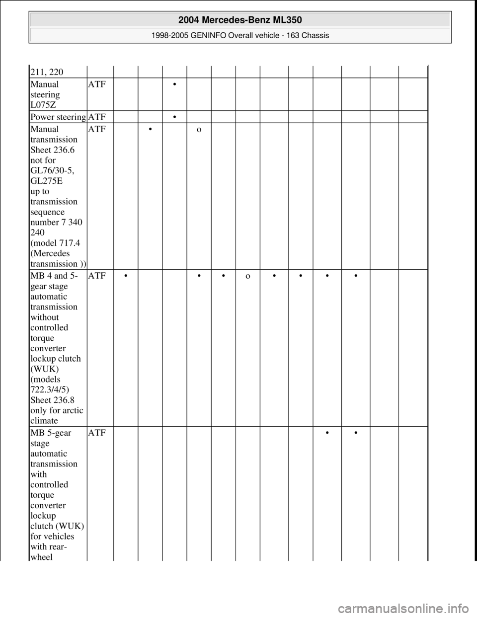
211, 220
Manual
steering
L075ZATF •
Power steeringATF •
Manual
transmission
Sheet 236.6
not for
GL76/30-5,
GL275E
up to
transmission
sequence
number 7 340
240
(model 717.4
(Mercedes
transmission ))ATF • o
MB 4 and 5-
gear stage
automatic
transmission
without
controlled
torque
converter
lockup clutch
(WUK)
(models
722.3/4/5)
Sheet 236.8
only for arctic
climateATF• ••o••••
MB 5-gear
stage
automatic
transmission
with
controlled
torque
converter
lockup
clutch (WUK)
for vehicles
with rear-
wheel ATF ••
2004 Mercedes-Benz ML350
1998-2005 GENINFO Overall vehicle - 163 Chassis
me
Saturday, October 02, 2010 3:47:56 PMPage 508 © 2006 Mitchell Repair Information Company, LLC.
Page 3232 of 4133
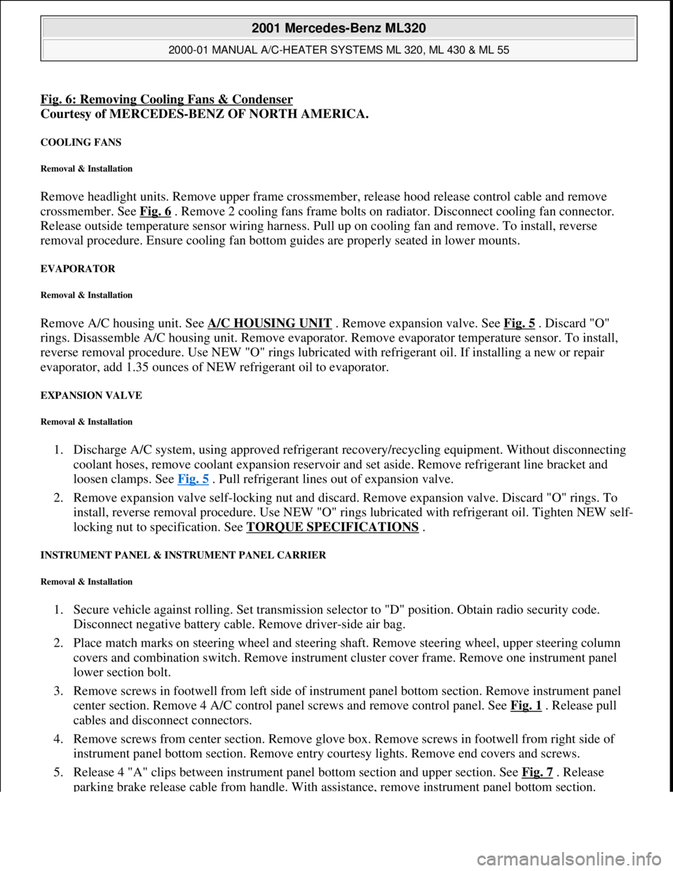
Fig. 6: Removing Cooling Fans & Condenser
Courtesy of MERCEDES-BENZ OF NORTH AMERICA.
COOLING FANS
Removal & Installation
Remove headlight units. Remove upper frame crossmember, release hood release control cable and remove
crossmember. See Fig. 6
. Remove 2 cooling fans frame bolts on radiator. Disconnect cooling fan connector.
Release outside temperature sensor wiring harness. Pull up on cooling fan and remove. To install, reverse
removal procedure. Ensure cooling fan bottom guides are properly seated in lower mounts.
EVAPORATOR
Removal & Installation
Remove A/C housing unit. See A/C HOUSING UNIT . Remove expansion valve. See Fig. 5 . Discard "O"
rings. Disassemble A/C housing unit. Remove evaporator. Remove evaporator temperature sensor. To install,
reverse removal procedure. Use NEW "O" rings lubricated with refrigerant oil. If installing a new or repair
evaporator, add 1.35 ounces of NEW refrigerant oil to evaporator.
EXPANSION VALVE
Removal & Installation
1. Discharge A/C system, using approved refrigerant recovery/recycling equipment. Without disconnecting
coolant hoses, remove coolant expansion reservoir and set aside. Remove refrigerant line bracket and
loosen clamps. See Fig. 5
. Pull refrigerant lines out of expansion valve.
2. Remove expansion valve self-locking nut and discard. Remove expansion valve. Discard "O" rings. To
install, reverse removal procedure. Use NEW "O" rings lubricated with refrigerant oil. Tighten NEW self-
locking nut to specification. See TORQUE SPECIFICATIONS
.
INSTRUMENT PANEL & INSTRUMENT PANEL CARRIER
Removal & Installation
1. Secure vehicle against rolling. Set transmission selector to "D" position. Obtain radio security code.
Disconnect negative battery cable. Remove driver-side air bag.
2. Place match marks on steering wheel and steering shaft. Remove steering wheel, upper steering column
covers and combination switch. Remove instrument cluster cover frame. Remove one instrument panel
lower section bolt.
3. Remove screws in footwell from left side of instrument panel bottom section. Remove instrument panel
center section. Remove 4 A/C control panel screws and remove control panel. See Fig. 1
. Release pull
cables and disconnect connectors.
4. Remove screws from center section. Remove glove box. Remove screws in footwell from right side of
instrument panel bottom section. Remove entry courtesy lights. Remove end covers and screws.
5. Release 4 "A" clips between instrument panel bottom section and upper section. See Fig. 7
. Release
parkin
g brake release cable from handle. With assistance, remove instrument panel bottom section.
2001 Mercedes-Benz ML320
2000-01 MANUAL A/C-HEATER SYSTEMS ML 320, ML 430 & ML 55
me
Saturday, October 02, 2010 3:25:10 PMPage 21 © 2006 Mitchell Repair Information Company, LLC.
Page 3493 of 4133
AR54.30-P-6015GH
Remove instrument cluster
20.1.97
MODEL
163.113 /128 /136 /154 /157 /172 /174 /175
P54.25-2680-06
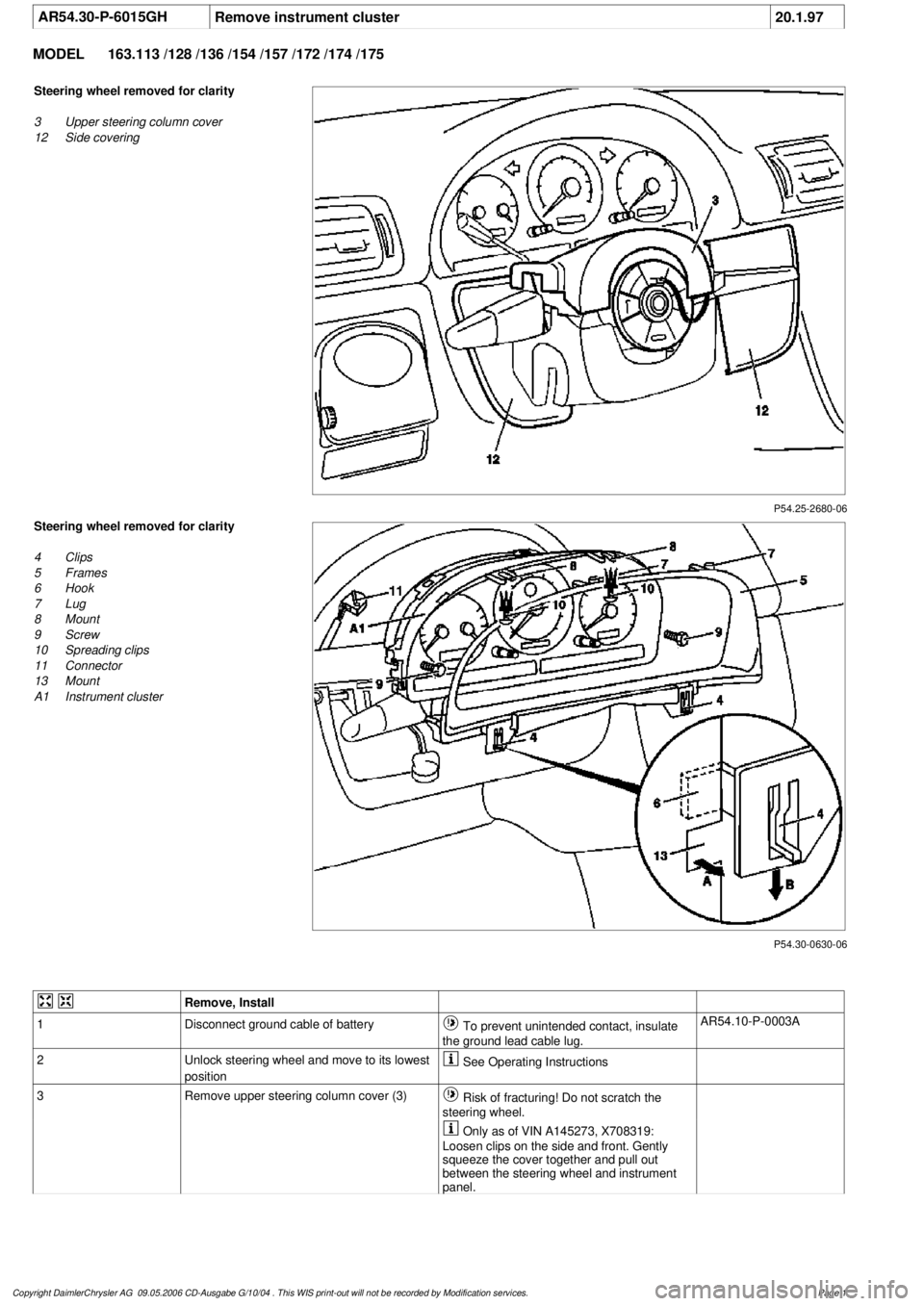
Steering wheel removed for clarity
3
Upper steering column cover
12
Side covering
P54.30-0630-06
Steering wheel removed for clarity
4
Clips
5
Frames
6
Hook
7
Lug
8
Mount
9
Screw
10
Spreading clips
11
Connector
13
Mount
A1
Instrument cluster
Remove, Install
1
Disconnect ground cable of battery
To prevent unintended contact, insulate
the ground lead cable lug.
AR54.10-P-0003A
2
Unlock steering wheel and move to its lowest
position
See Operating Instructions
3
Remove upper steering column cover (3)
Risk of fracturing! Do not scratch the
steering wheel.
Only as of VIN A145273, X708319:
Loosen clips on the side and front. Gently
squeeze the cover together and pull out
between the steering wheel and instrument
panel.
Copyright DaimlerChrysler AG 09.05.2006 CD-Ausgabe G/10/04 . This WIS print-out will not be recorde
d by Modification services.
Page 1