Page 2145 of 4133
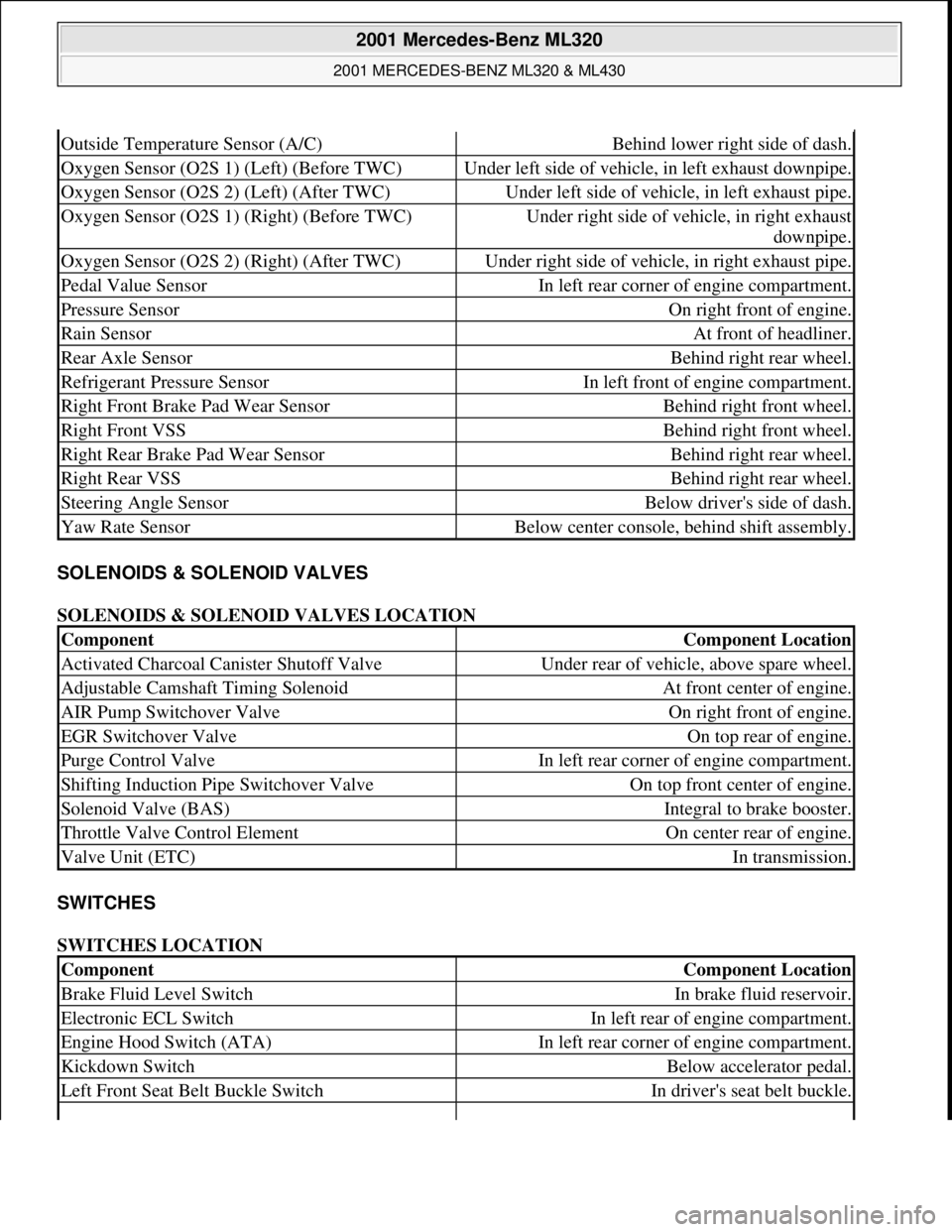
SOLENOIDS & SOLENOID VALVES
SOLENOIDS & SOLENOID VALVES LOCATION
SWITCHES
SWITCHES LOCATION
Outside Temperature Sensor (A/C)Behind lower right side of dash.
Oxygen Sensor (O2S 1) (Left) (Before TWC)Under left side of vehicle, in left exhaust downpipe.
Oxygen Sensor (O2S 2) (Left) (After TWC)Under left side of vehicle, in left exhaust pipe.
Oxygen Sensor (O2S 1) (Right) (Before TWC)Under right side of vehicle, in right exhaust
downpipe.
Oxygen Sensor (O2S 2) (Right) (After TWC)Under right side of vehicle, in right exhaust pipe.
Pedal Value SensorIn left rear corner of engine compartment.
Pressure SensorOn right front of engine.
Rain SensorAt front of headliner.
Rear Axle SensorBehind right rear wheel.
Refrigerant Pressure SensorIn left front of engine compartment.
Right Front Brake Pad Wear SensorBehind right front wheel.
Right Front VSSBehind right front wheel.
Right Rear Brake Pad Wear SensorBehind right rear wheel.
Right Rear VSSBehind right rear wheel.
Steering Angle SensorBelow driver's side of dash.
Yaw Rate SensorBelow center console, behind shift assembly.
ComponentComponent Location
Activated Charcoal Canister Shutoff ValveUnder rear of vehicle, above spare wheel.
Adjustable Camshaft Timing SolenoidAt front center of engine.
AIR Pump Switchover ValveOn right front of engine.
EGR Switchover ValveOn top rear of engine.
Purge Control ValveIn left rear corner of engine compartment.
Shifting Induction Pipe Switchover ValveOn top front center of engine.
Solenoid Valve (BAS)Integral to brake booster.
Throttle Valve Control ElementOn center rear of engine.
Valve Unit (ETC)In transmission.
ComponentComponent Location
Brake Fluid Level SwitchIn brake fluid reservoir.
Electronic ECL SwitchIn left rear of engine compartment.
Engine Hood Switch (ATA)In left rear corner of engine compartment.
Kickdown SwitchBelow accelerator pedal.
Left Front Seat Belt Buckle SwitchIn driver's seat belt buckle.
2001 Mercedes-Benz ML320
2001 MERCEDES-BENZ ML320 & ML430
me
Saturday, October 02, 2010 3:21:17 PMPage 5 © 2006 Mitchell Repair Information Company, LLC.
Page 2524 of 4133
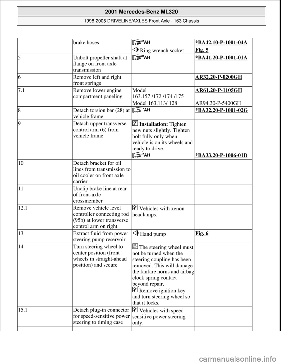
brake hoses *BA42.10-P-1001-04A
Ring wrench socketFig. 5
5Unbolt propeller shaft at
flange on front axle
transmission *BA41.20-P-1001-01A
6Remove left and right
front springs AR32.20-P-0200GH
7.1Remove lower engine
compartment panelingModel
163.157 /172 /174 /175AR61.20-P-1105GH
Model 163.113/ 128AR94.30-P-5400GH
8Detach torsion bar (28) at
vehicle frame *BA32.20-P-1001-02G
9Detach upper transverse
control arm (6) from
vehicle frame Installation: Tighten
new nuts slightly. Tighten
bolt fully only when
vehicle is on its wheels and
ready to drive.
*BA33.20-P-1006-01D
10Detach bracket for oil
lines from transmission to
oil cooler on front axle
carrier
11Unclip brake line at rear
of front-axle
crossmember
12.1Remove vehicle level
controller connecting rod
(95b) at lower transverse
control arm on right Vehicles with xenon
headlamps.
13Extract fluid from power
steering pump reservoir Hand pumpFig. 6
14Turn steering wheel to
center position (front
wheels in straight-ahead
position) and secureThe steering wheel must
not be turned when the
steering coupling has been
removed. This will damage
the fanfare horns and airbag
clock spring contact
beyond repair.
Remove ignition key
and turn steering wheel so
that it locks.
15.1Detach plug-in connector
for speed-sensitive power
steering to timing case Vehicles with speed-
sensitive power steering
only.
2001 Mercedes-Benz ML320
1998-2005 DRIVELINE/AXLES Front Axle - 163 Chassis
me
Saturday, October 02, 2010 3:38:21 PMPage 5 © 2006 Mitchell Repair Information Company, LLC.
Page 2526 of 4133
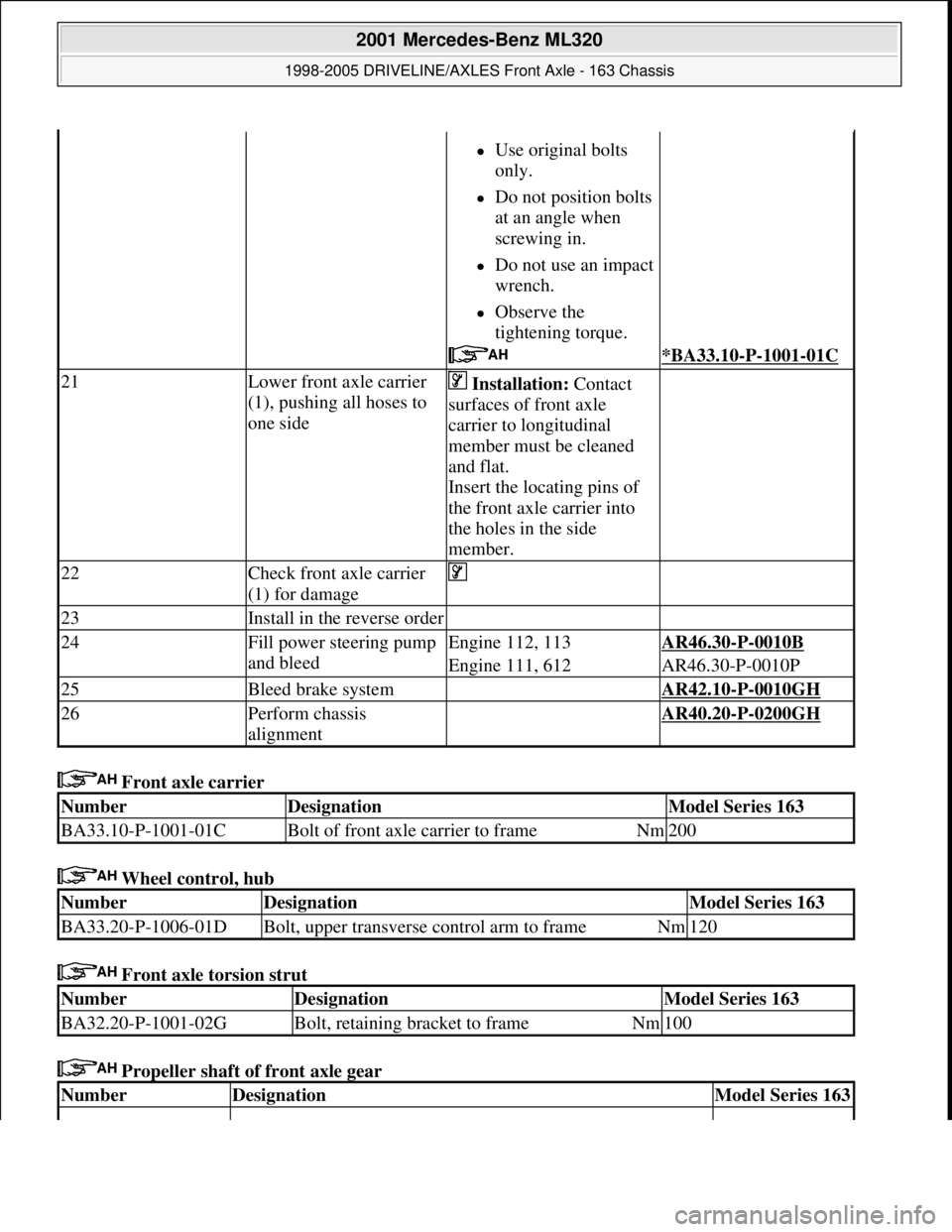
Front axle carrier
Wheel control, hub
Front axle torsion strut
Propeller shaft of front axle gear
Use original bolts
only.
Do not position bolts
at an angle when
screwing in.
Do not use an impact
wrench.
Observe the
tightening torque.
*BA33.10-P-1001-01C
21Lower front axle carrier
(1), pushing all hoses to
one side Installation: Contact
surfaces of front axle
carrier to longitudinal
member must be cleaned
and flat.
Insert the locating pins of
the front axle carrier into
the holes in the side
member.
22Check front axle carrier
(1) for damage
23Install in the reverse order
24Fill power steering pump
and bleedEngine 112, 113AR46.30-P-0010B
Engine 111, 612AR46.30-P-0010P
25Bleed brake system AR42.10-P-0010GH
26Perform chassis
alignment AR40.20-P-0200GH
NumberDesignationModel Series 163
BA33.10-P-1001-01CBolt of front axle carrier to frameNm200
NumberDesignationModel Series 163
BA33.20-P-1006-01DBolt, upper transverse control arm to frameNm120
NumberDesignationModel Series 163
BA32.20-P-1001-02GBolt, retaining bracket to frameNm100
NumberDesignationModel Series 163
2001 Mercedes-Benz ML320
1998-2005 DRIVELINE/AXLES Front Axle - 163 Chassis
me
Saturday, October 02, 2010 3:38:21 PMPage 7 © 2006 Mitchell Repair Information Company, LLC.
Page 2533 of 4133
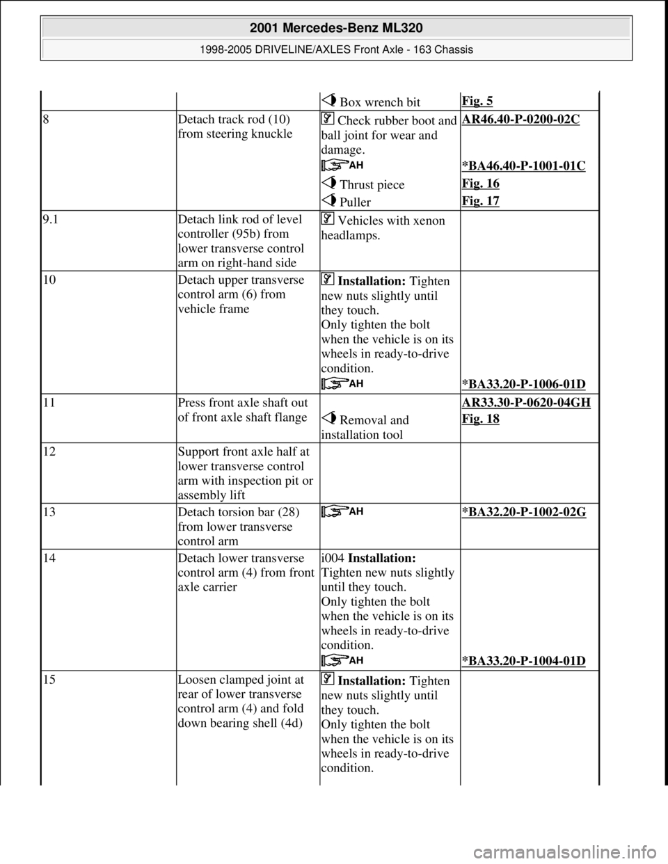
Box wrench bitFig. 5
8Detach track rod (10)
from steering knuckleCheck rubber boot and
ball joint for wear and
damage.AR46.40-P-0200-02C
*BA46.40-P-1001-01C
Thrust pieceFig. 16
PullerFig. 17
9.1Detach link rod of level
controller (95b) from
lower transverse control
arm on right-hand side Vehicles with xenon
headlamps.
10Detach upper transverse
control arm (6) from
vehicle frame Installation: Tighten
new nuts slightly until
they touch.
Only tighten the bolt
when the vehicle is on its
wheels in ready-to-drive
condition.
*BA33.20-P-1006-01D
11Press front axle shaft out
of front axle shaft flange AR33.30-P-0620-04GH
Removal and
installation toolFig. 18
12Support front axle half at
lower transverse control
arm with inspection pit or
assembly lift
13Detach torsion bar (28)
from lower transverse
control arm *BA32.20-P-1002-02G
14Detach lower transverse
control arm (4) from front
axle carrieri004 Installation:
Tighten new nuts slightly
until they touch.
Only tighten the bolt
when the vehicle is on its
wheels in ready-to-drive
condition.
*BA33.20-P-1004-01D
15Loosen clamped joint at
rear of lower transverse
control arm (4) and fold
down bearing shell (4d) Installation: Tighten
new nuts slightly until
they touch.
Only tighten the bolt
when the vehicle is on its
wheels in ready-to-drive
condition.
2001 Mercedes-Benz ML320
1998-2005 DRIVELINE/AXLES Front Axle - 163 Chassis
me
Saturday, October 02, 2010 3:38:22 PMPage 14 © 2006 Mitchell Repair Information Company, LLC.
Page 2534 of 4133
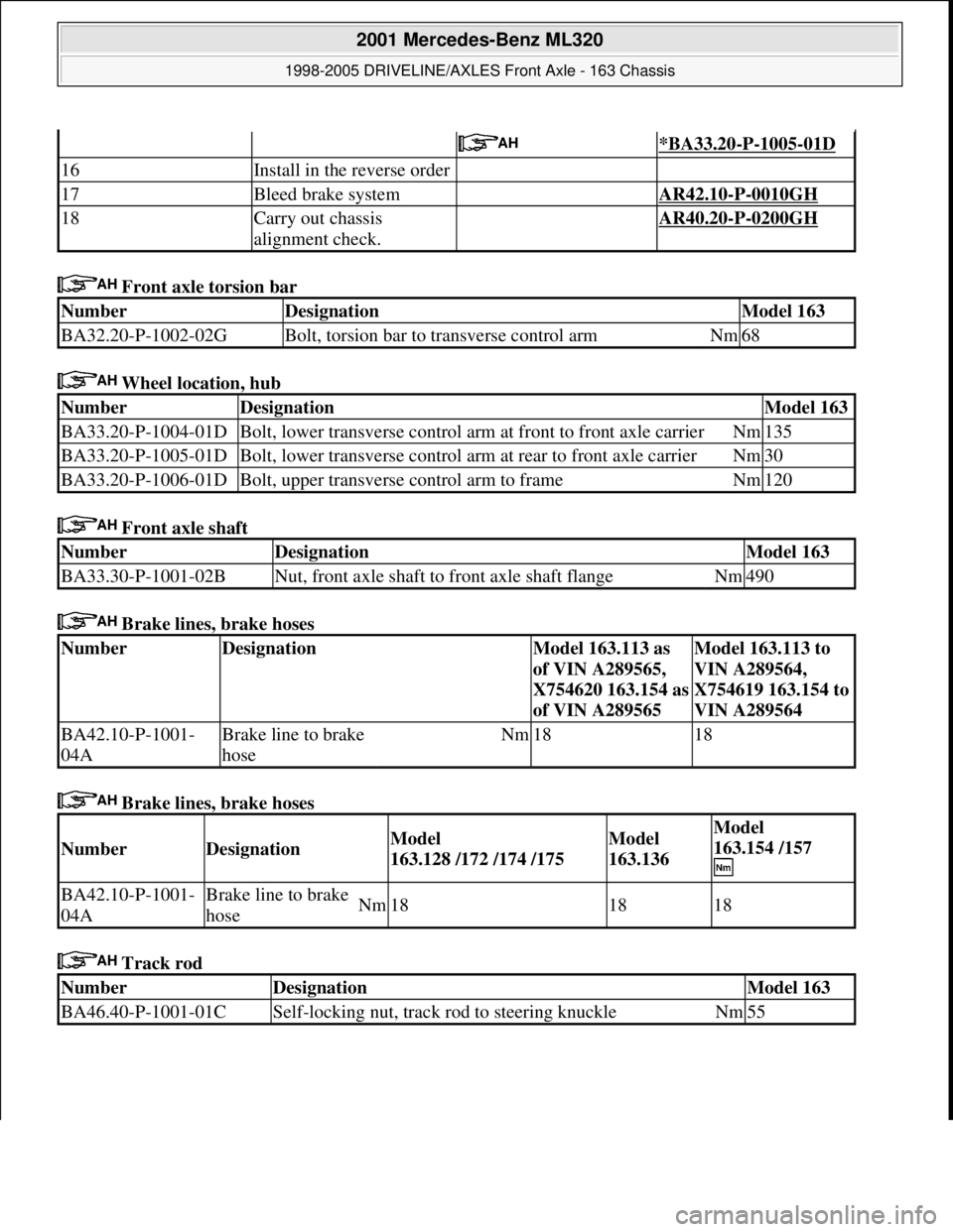
Front axle torsion bar
Wheel location, hub
Front axle shaft
Brake lines, brake hoses
Brake lines, brake hoses
Track rod
*BA33.20-P-1005-01D
16Install in the reverse order
17Bleed brake system AR42.10-P-0010GH
18Carry out chassis
alignment check. AR40.20-P-0200GH
NumberDesignationModel 163
BA32.20-P-1002-02GBolt, torsion bar to transverse control armNm68
NumberDesignationModel 163
BA33.20-P-1004-01DBolt, lower transverse control arm at front to front axle carrierNm135
BA33.20-P-1005-01DBolt, lower transverse control arm at rear to front axle carrierNm30
BA33.20-P-1006-01DBolt, upper transverse control arm to frameNm120
NumberDesignationModel 163
BA33.30-P-1001-02BNut, front axle shaft to front axle shaft flangeNm490
NumberDesignationModel 163.113 as
of VIN A289565,
X754620 163.154 as
of VIN A289565Model 163.113 to
VIN A289564,
X754619 163.154 to
VIN A289564
BA42.10-P-1001-
04ABrake line to brake
hoseNm1818
NumberDesignationModel
163.128 /172 /174 /175Model
163.136Model
163.154 /157
BA42.10-P-1001-
04ABrake line to brake
hoseNm181818
NumberDesignationModel 163
BA46.40-P-1001-01CSelf-locking nut, track rod to steering knuckleNm55
2001 Mercedes-Benz ML320
1998-2005 DRIVELINE/AXLES Front Axle - 163 Chassis
me
Saturday, October 02, 2010 3:38:22 PMPage 15 © 2006 Mitchell Repair Information Company, LLC.
Page 2541 of 4133
Fig. 31: Identifying Front Axle Shaft Flange And Double-Row Angular Ball Bearing Components
Modification notes
7.8.00Pulling out front axle
shaft flange, changed
Step 2:
The front axle shaft flange is now pulled out using a
stationary press and not with the auxiliary hydraulic
press.
AR33.20-P-
0315-01GI
Remove/Install
1Remove steering knuckle AR33.25-P-
0400GH
2Pull out front axle shaft flange (9)
AR33.20-P-
0315-01GI
Extractor toolFig. 19
Extraction and insertion toolFig. 20
3Detach circlip (9p)
Installation: Ensure that the circlip
seats securely in the wheel carrier.
Pliers for locking ring*WH58.30-Z-
1009-02A
4Pull double-row angular ball bearing
(9n) out of steering knuckle AR33.20-P-
0315-03GH
Extraction and insertion toolFig. 20
AR33.20-P-
0315-04GH
2001 Mercedes-Benz ML320
1998-2005 DRIVELINE/AXLES Front Axle - 163 Chassis
me
Saturday, October 02, 2010 3:38:22 PMPage 22 © 2006 Mitchell Repair Information Company, LLC.
Page 2544 of 4133
Fig. 37: Identifying Follower Joint Of Steering Knuckle Mount
PRESSING OUT AND ATTACHING SUPPORTING JOINT AT STEERING KNUCKLE - AR33.20-P-0440-01GH
Wheel location, hub
Fig. 38: Identifying Prong Wrench (385 589 00 07 00)
Remove
1. Push supporting joint (7) out of steering knuckle using suitable tool.
Inspect
1Raise front of vehicle
2Check rubber boot (8f) for cracks and damage
3
Check play in follower joint (8) by firmly
pulling and pushing on the front wheel while
feeling the ball joint at the same time.
If inspection indicates that upper
control (6) arm should be replaced,
proceed as follows: ?
Upper control arm, removal and
installationAR33.20-P-
0500GH
NumberDesignationModel Series 163
BA33.20-P-1003-01DLocking slotted nut, supporting joint to steering knuckleNM300
2001 Mercedes-Benz ML320
1998-2005 DRIVELINE/AXLES Front Axle - 163 Chassis
me
Saturday, October 02, 2010 3:38:22 PMPage 25 © 2006 Mitchell Repair Information Company, LLC.
Page 2545 of 4133
Fig. 39: Identifying Steering Knuckle Supporting Joint
Install
2. Insert supporting joint (7) and attach locking grooved nut (7) .
3. Pull in supporting joint (7) using claw-type wrench (044) until it abuts.
Fig. 40: Identifying Steering Knuckle Supporting Joint And Attaching Locking Grooved Nut
PRESSING OFF AND ATTACHING SUPPORTING JOINT AT LOWER WISHBONE - AR33.20-P-0440-02GH
Wheel location, hub
NumberDesignationModel Series 163
BA33.20-P-1002-01DSelf-locking nut, supporting joint to steering knuckleNM85
2001 Mercedes-Benz ML320
1998-2005 DRIVELINE/AXLES Front Axle - 163 Chassis
me
Saturday, October 02, 2010 3:38:22 PMPage 26 © 2006 Mitchell Repair Information Company, LLC.