1997 MERCEDES-BENZ ML430 steering wheel
[x] Cancel search: steering wheelPage 3897 of 4133

2
Remove screws (2)
Starting from the straight-ahead position,
turn steering wheel by 90 to obtain better
access to the bolts.
*BA91.60-P-1001-01A
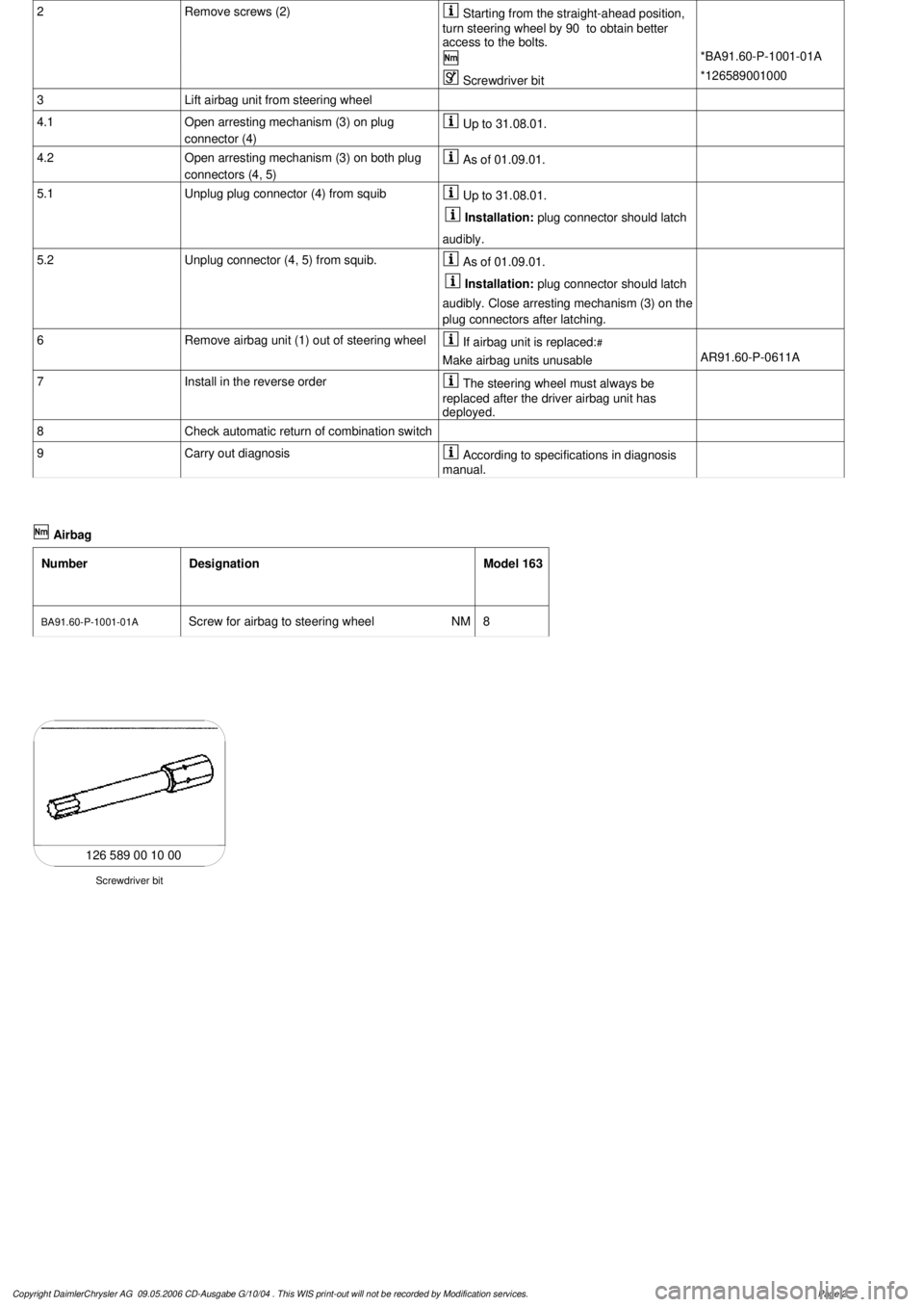
Screwdriver bit
*126589001000
3
Lift airbag unit from steering wheel
4.1
Open arresting mechanism (3) on plug
connector (4)
Up to 31.08.01.
4.2
Open arresting mechanism (3) on both plug
connectors (4, 5)
As of 01.09.01.
5.1
Unplug plug connector (4) from squib
Up to 31.08.01.
Installation:
plug connector should latch
audibly.
5.2
Unplug connector (4, 5) from squib.
As of 01.09.01.
Installation:
plug connector should latch
audibly. Close arresting mechanism (3) on the
plug connectors after latching.
6
Remove airbag unit (1) out of steering wheel
If airbag unit is replaced:
#
Make airbag units unusable
AR91.60-P-0611A
7
Install in the reverse order
The steering wheel must always be
replaced after the driver airbag unit has
deployed.
8
Check automatic return of combination switch
9
Carry out diagnosis
According to specifications in diagnosis
manual.
Airbag
Number
Designation
Model 163
BA91.60-P-1001-01A
Screw for airbag to steering wheel
NM
8
126 589 00 10 00
Screwdriver bit
Copyright DaimlerChrysler AG 09.05.2006 CD-Ausgabe G/10/04 . This WIS print-out will not be recorde
d by Modification services.
Page 2
Page 3898 of 4133

AR46.10-P-0200GH
Removing, installing contact spiral
1.3.97
MODEL
163.113 /128 /136 /154 /157 /172 /174 /175
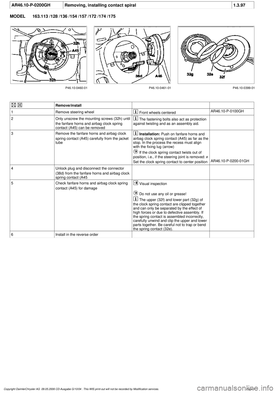
P46.10-0460-01 P46.10-0461-01 P46.10-0399-01
Remove/install
1
Remove steering wheel
Front wheels centered
AR46.10-P-0100GH
2
Only unscrew the mounting screws (32h) until
the fanfare horns and airbag clock spring
contact (A45) can be removed
The fastening bolts also act as protection
against twisting and as an assembly aid.
3
Remove the fanfare horns and airbag clock
spring contact (A45) carefully from the jacket
tube
Installation:
Push on fanfare horns and
airbag clock spring contact (A45) as far as the
stop. In the process the recess must align
with the fixing lug (arrow)
If the clock spring contact twists out of
position, i.e., if the steering joint is removed:
#
Set the clock spring contact to center position
AR46.10-P-0200-01GH
4
Unlock plug and disconnect the connector
(38d) from the fanfare horns and airbag clock
spring contact (A45
5
Check fanfare horns and airbag clock spring
contact (A45) for damage
Visual inspection
Do not use any oil or grease!
The upper (32f) and lower part (32g) of
the clock spring contact are clipped together
and can only be separated by the effect of
high forces or due to defective assembly. If
the spring contact is assembled incorrectly,
carefully unwind and clip the upper and lower
parts together. Be careful not to trap or bend
the spring contact (32e).
6
Install in the reverse order
Copyright DaimlerChrysler AG 09.05.2006 CD-Ausgabe G/10/04 . This WIS print-out will not be recorde
d by Modification services.
Page 1
Page 3899 of 4133

AR46.10-P-0100GHRemoving and installing steering wheel
1.3.97
MODEL
163.113 /128 /136 /154 /157 /172 /174 /175
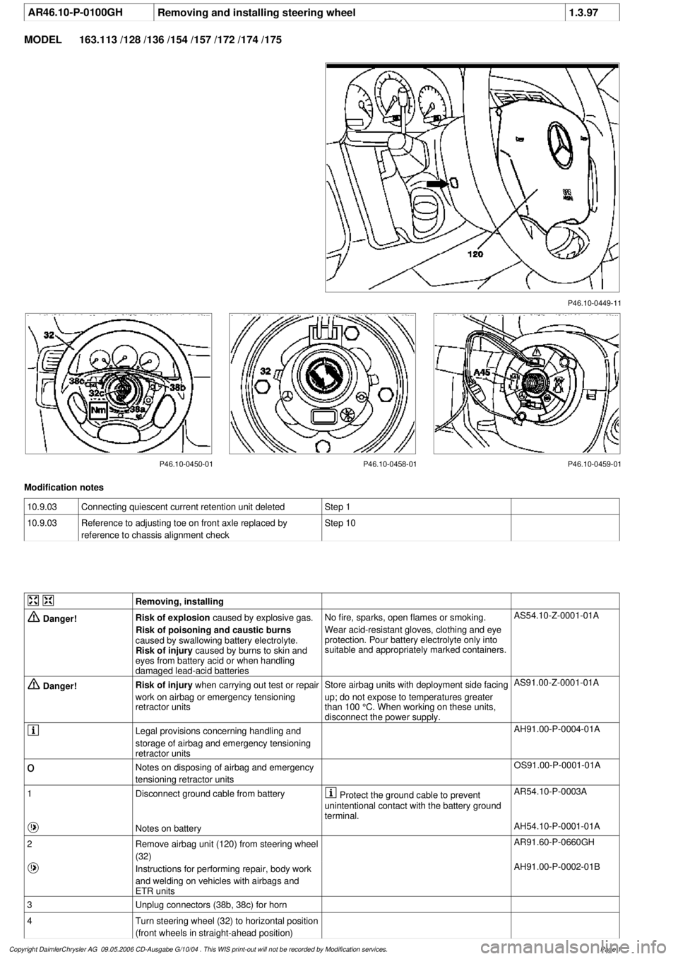
P46.10-0449-11
P46.10-0450-01 P46.10-0458-01 P46.10-0459-01
Modification notes
10.9.03
Connecting quiescent current retention unit deleted
Step 1
10.9.03
Reference to adjusting toe on front axle replaced by
reference to chassis alignment check
Step 10
Removing, installing
Danger!
Risk of explosion
caused by explosive gas.
Risk of poisoning and caustic burns
caused by swallowing battery electrolyte.
Risk of injury
caused by burns to skin and
eyes from battery acid or when handling
damaged lead-acid batteries
No fire, sparks, open flames or smoking.
Wear acid-resistant gloves, clothing and eye
protection. Pour battery electrolyte only into
suitable and appropriately marked containers.
AS54.10-Z-0001-01A
Danger!
Risk of injury
when carrying out test or repair
work on airbag or emergency tensioning
retractor units
Store airbag units with deployment side facing
up; do not expose to temperatures greater
than 100 °C. When working on these units,
disconnect the power supply.
AS91.00-Z-0001-01A
Legal provisions concerning handling and
storage of airbag and emergency tensioning
retractor units
AH91.00-P-0004-01A
o
Notes on disposing of airbag and emergency
tensioning retractor units
OS91.00-P-0001-01A
1
Disconnect ground cable from battery
Protect the ground cable to prevent
unintentional contact with the battery ground
terminal.
AR54.10-P-0003A
Notes on battery
AH54.10-P-0001-01A
2
Remove airbag unit (120) from steering wheel
(32)
AR91.60-P-0660GH
Instructions for performing repair, body work
and welding on vehicles with airbags and
ETR units
AH91.00-P-0002-01B
3
Unplug connectors (38b, 38c) for horn
4
Turn steering wheel (32) to horizontal position
(front wheels in straight-ahead position)
Copyright DaimlerChrysler AG 09.05.2006 CD-Ausgabe G/10/04 . This WIS print-out will not be recorde
d by Modification services.
Page 1
Page 3900 of 4133

5
Remove key and engage steering lock
6
Unscrew bolt (32c)
Hold the steering wheel (32).
Installation:
Replace bolt (32c).
*BA46.10-P-1001-02A
7
Pull off steering wheel (32)
Pass cables carefully through the openings.
Installation:
Align recesses of the splines
in the steering wheel with the markings on the
steering shaft (arrows).
8
Check fanfare horns and airbag clock spring
contact (A45) for damage
The clock spring contact must not be
turned while the steering wheel is removed
otherwise it will be damaged.
Visual inspection, replace clock spring
contact if necessary:
#
Removing and installing clock spring contact
AR46.10-P-0200GH
9
Install in the reverse order
10
Carry out road test
Tests during the road test:
Turn signal canceling:
When the steering wheel is offset by
more than 1 tooth, satisfactory resetting of the
turn signal is no longer guaranteed.
Airbag indicator lamp:
The SRS indicator lamp must not light up
on full steering lock in both directions.
Steering wheel position:
If the steering wheel is crooked, adjust it
by max. 1 tooth. If the difference is greater:
#
Check toe on front axle and adjust if
necessary, see:
#
Performing chassis alignment check
AR40.20-P-0200A
Steering wheel
Number
Designation
Model 163
BA46.10-P-1001-02A
Bolt, steering wheel to steering shaft
Nm
80
Copyright DaimlerChrysler AG 09.05.2006 CD-Ausgabe G/10/04 . This WIS print-out will not be recorde
d by Modification services.
Page 2
Page 3942 of 4133

AR46.40-P-0200GH
Removing and installing tie rod
12.3.97
MODEL
163.113 /128 /136 /154 /157 /172 /174 /175
P46.40-0262-12
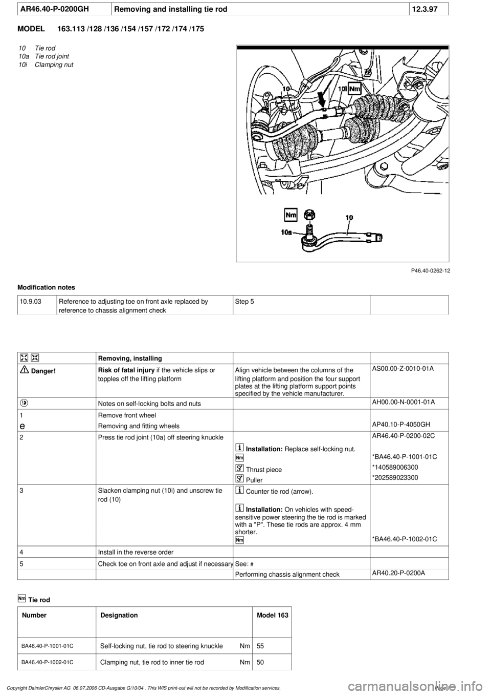
10
Tie rod
10a
Tie rod joint
10i
Clamping nut
Modification notes
10.9.03
Reference to adjusting toe on front axle replaced by
reference to chassis alignment check
Step 5
Removing, installing
Danger!
Risk of fatal injury
if the vehicle slips or
topples off the lifting platform
Align vehicle between the columns of the
lifting platform and position the four support
plates
at the lifting platform support points
specified by the vehicle manufacturer.
AS00.00-Z-0010-01A
Notes on self-locking bolts and nuts
AH00.00-N-0001-01A
1
Remove front wheel
e
Removing and fitting wheels
AP40.10-P-4050GH
2
Press tie rod joint (10a) off steering knuckle
AR46.40-P-0200-02C
Installation:
Replace self-locking nut.
*BA46.40-P-1001-01C
Thrust piece
*140589006300
Puller
*202589023300
3
Slacken clamping nut (10i) and unscrew tie
rod (10)
Counter tie rod (arrow).
Installation:
On vehicles with speed-
sensitive power steering the tie rod is marked
with a "P". These tie rods are approx. 4 mm
shorter.
*BA46.40-P-1002-01C
4
Install in the reverse order
5
Check toe on front axle and adjust if necessary
See:
#
Performing chassis alignment check
AR40.20-P-0200A
Tie rod
Number
Designation
Model 163
BA46.40-P-1001-01C
Self-locking nut, tie rod to steering knuckle
Nm
55
BA46.40-P-1002-01C
Clamping nut, tie rod to inner tie rod
Nm
50
Copyright DaimlerChrysler AG 06.07.2006 CD-Ausgabe G/10/04 . This WIS print-out will not be recorde
d by Modification services.
Page 1
Page 3966 of 4133

3
Features
This telephone system is fully integrated with your Mercedes-Benz audio system and steering wheel switches
*
. You can
scroll through the first 99 entries in your phone book and access the entire phone number memory; place, receive, and
terminate calls; change volume; and view call status (such as Ready, Dialing, Incoming Call, Call Active, No Service, Redial,
etc.). Because exact phone features are dependent on the particular audio system installed in your vehicle, detailed oper-
ation is covered in your audio system manual. Please refer to it.
Notes:
• In order for your Mercedes-Benz volume controls to work in conjunction with your Motorola phone (to change ringer
volume or adjust call volume), the vehicle must have either the engine running or the ignition key turned clockwise
to the last position before starting the engine.
• Your phone includes many new features that take additional time to initialize, resulting in increased power up/down
time. Please wait until the phone is completely powered up before using any feature from both the radio and phone
controls.
Finding Information on Phone Features
Your new Mercedes-Benz telephone operates in two modes:
•
Vehicular Mode
—when the phone is inserted and snapped into the privacy cradle in the vehicle
•
Portable Mode
—when the phone is operating as a stand alone device (NOT inserted and snapped into the privacy
cradle in the vehicle)
Most features of your new Mercedes-Benz telephone are available in both modes.
This guide contains basic information on using your phone in Vehicular Mode to place and receive calls.
* Not available on all models.
Page 3971 of 4133

8
Placing a Call Using Hands Free Operation
Hands Free operation allows you to use the phone while it is docked in the cradle. The phone audio is projected through
your vehicle’s audio system speakers. The Hands Free microphone allows both driver and passenger to engage in the con-
versation.
Step
11 1 1
Prepare the phone for Hands Free use:
• Dock the phone. (See “Switching into Vehicular Mode” on page 5.)
• Ensure the flip is closed.
22 2 2
Dial the telephone number via the radio keypad or via voice command.
*
NN N N
oo o o
tt t t
ee e e
::: :
You can enter up to 32 digits.
* Not available on all models.
33 3 3
Press Send on the radio keypad or steering wheel, or speak the voice command: “Dial.”
*
If the network is busy, you hear a fast busy signal. Your phone automatically redials over the next four minutes. When the call
goes through, your phone rings one time and connects the call.
44 4 4
Begin your conversation.
55 5 5
To end the call, press the End key on the radio keypad, steering wheel, or voice activation stalk.
*
Page 3972 of 4133

9
Placing a Call Using Handset Operation
In handset operation, the cellular phone remains in the cradle, but the cradle is removed from the holder and the phone is
held to your ear with the flip open. In this mode, passengers in the vehicle are prevented from hearing the person on the
other end of the call.
Step
11 1 1
With the phone properly docked, dial the number you are calling.
NN N N
oo o o
tt t t
ee e e
::: :
You may also dial the number with the phone out of the cradle.
If your audio system is on when you make a call, it automatically mutes to allow the person you are calling to be heard.
22 2 2
Press the Send button on the phone, radio keypad, or steering wheel
*
to initiate the call.
* Not available on all models.
33 3 3
Remove the phone and cradle from the holder, lift the phone to your ear, and begin your conversation.
NN N N
oo o o
tt t t
ee e e
::: :
Your phone will display the In Use icon while the call is active.
44 4 4
When you are finished with the call, press
O
on the phone, head unit, or steering wheel.