1997 MERCEDES-BENZ ML430 steering wheel
[x] Cancel search: steering wheelPage 3494 of 4133
4
Remove side covers (12)
Danger of breaking retaining lugs. Do not
damage instrument panel.
Up to VIN A145272, X708318:
3 covers:
Remove side covers first. Detach center
cover from instrument panel and rotate so
that the retaining lugs point upwards. Then
pull out to the right.
As of VIN A145273, X708319:
2 covers: First
remove the right cover, then the left. It is not
necessary to detach the connectors. The
covers can remain attached to the wiring
harness.
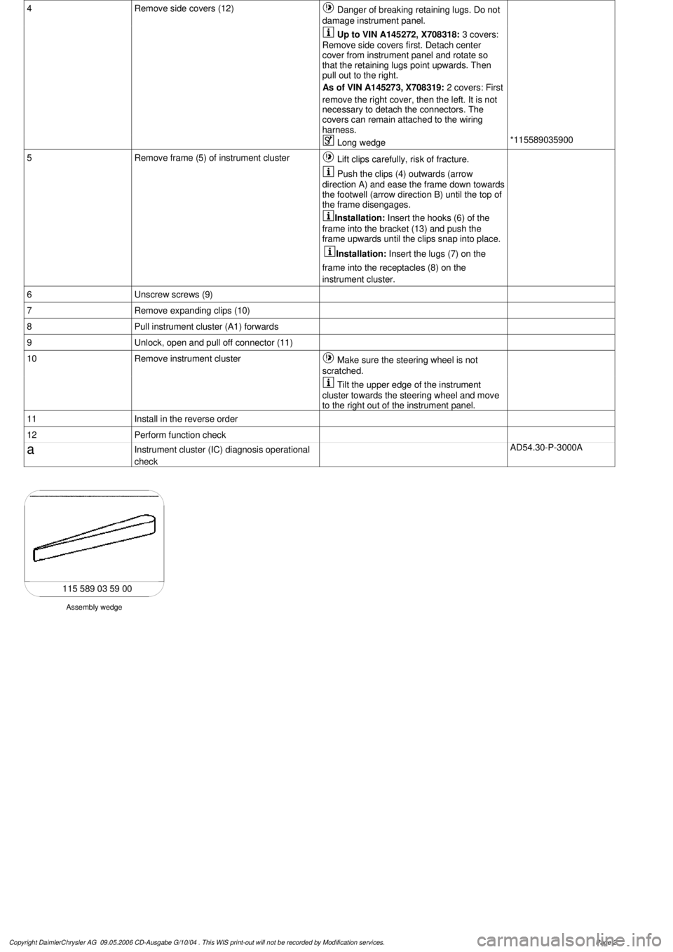
Long wedge
*115589035900
5
Remove frame (5) of instrument cluster
Lift clips carefully, risk of fracture.
Push the clips (4) outwards (arrow
direction A) and ease the frame down towards
the footwell (arrow direction B) until the top of
the frame disengages.
Installation:
Insert the hooks (6) of the
frame into the bracket (13) and push the
frame upwards until the clips snap into place.
Installation:
Insert the lugs (7) on the
frame into the receptacles (8) on the
instrument cluster.
6
Unscrew screws (9)
7
Remove expanding clips (10)
8
Pull instrument cluster (A1) forwards
9
Unlock, open and pull off connector (11)
10
Remove instrument cluster
Make sure the steering wheel is not
scratched.
Tilt the upper edge of the instrument
cluster towards the steering wheel and move
to the right out of the instrument panel.
11
Install in the reverse order
12
Perform function check
a
Instrument cluster (IC) diagnosis operational
check
AD54.30-P-3000A
Assembly wedge
115 589 03 59 00
Copyright DaimlerChrysler AG 09.05.2006 CD-Ausgabe G/10/04 . This WIS print-out will not be recorde
d by Modification services.
Page 2
Page 3498 of 4133

AF54.30-P-8400A
Instrument cluster indicates: Oil sensor defective, oil level below min. or oil level
above max. with engine running and at operating temperature. No DTC stored.
19.5.98
MODEL
129.0, 163.1, 202.0, 208.3 /4, 210.0 /2 /6, 220.0 /1 with ENGINE 112
MODEL
129.0, 163.1, 202.0, 208.3 /4, 210.0 /2, 220.0 /1 with ENGINE 113
Damage code
Cause
Remedy
54 201 90
Oil low, connector defective or coding error
1
Shut off engine and wait 2 min. (key
position 0)
Instrument cluster indicates oil sensor
defective, oil level below min. or oil level
above max. with engine warm and running.
No DTC stored in DTC memory!
2
Check oil level with oil dipstick
3
Check oil level on instrument cluster:
- Key in steering wheel lock position 2,
engine not running
- Wait until - - - - - - appears on
instrument cluster
- When this is displayed press the reset
button for the tripodometer twice within
1 sec. (display appears only after
expiration of a waiting time (max. 30
min.) depending on engine oil
temperature)
Oil level is at bottom mark on oil dipstick
and instrument cluster indicates:
-1L
, -
1,5L
or -2L
#
4
Add quantity of oil indicated on
instrument cluster display and repeat
test.
Oil level at upper mark on dipstick and
instrument cluster indicates either oil level
okay or -1L
, -
1,5L
, -2L
#
5
Recode instrument cluster
AF54.30-P-8600A
Problem still present
#
6
Check cable to oil sensor, oil sensor
connectors, control module and fuse
box (see wiring diagram) for good contact
Copyright DaimlerChrysler AG 05.06.2006 CD-Ausgabe G/10/04 . This WIS print-out will not be recorde
d by Modification services.
Page 1
Page 3503 of 4133
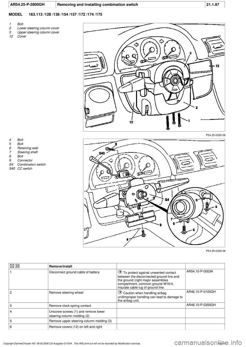
AR54.25-P-2800GH
Removing and installing combination switch
21.1.97
MODEL
163.113 /128 /136 /154 /157 /172 /174 /175
P54.25-0325-06
1
Bolt
2
Lower steering column cover
3
Upper steering column cover
12
Cover
P54.25-0333-06
4
Bolt
5
Bolt
6
Retaining web
7
Steering shaft
8
Bolt
9
Connector
S4
Combination switch
S40
CC switch
Remove/install
1
Disconnect ground cable of battery
To protect against unwanted contact
between the disconnected ground line and
the ground (right major assemblies
compartment, common ground W16/4,
insulate cable lug of ground line.
AR54.10-P-0003A
2
Remove steering wheel
Caution when handling airbag
unitImproper handling can lead to damage to
the airbag unit.
AR46.10-P-0100GH
3
Remove clock spring contact
AR46.10-P-0200GH
4
Unscrew screws (1) and remove lower
steering column molding (2)
5
Remove upper steering column molding (3)
6
Remove covers (12) on left and right
Copyright DaimlerChrysler AG 09.05.2006 CD-Ausgabe G/10/04 . This WIS print-out will not be recorde
d by Modification services.
Page 1
Page 3594 of 4133
MODEL all
CLEAN INSTRUMENT CLUSTER, STEERING WHEEL AND GEARSHIFT LEVER (STANDARD VERSION) - AP68.10-P-
1000-01A
all
Work procedure
Wipe off with moist, lent-free rag.
Do not use scouring agent to prevent scratching surfaces.
Do not bring Plexiglas cover on instrument cluster and Mercedes Star in steering wheel into contact with
solvent or cleaning agents containing solvents (danger of tension cracking).
Do not apply liquids to Plexiglas cover on instrument cluster.
Repair materials
Cleaning vehicle headliners of textile material (prefabricated headliners), floor
coverings, rear shelf coverings, and other textiles AP68.00-P-
1000-01A
Cleaning synthetic leather vehicle headliners (tensioned headliners) AP68.00-P-
1000-02A
Cleaning seat belts AP91.40-P-
1000-01A
Cleaning instrument cluster, steering wheel and gearshift lever (standard version) AP68.10-P-
1000-01A
Cleaning leather upholstery, leather steering wheel, and leather gearshift lever AP91.18-P-
1000-01A
Cleaning plastic covering parts AP68.30-P-
1000-01A
Cleaning MB Tex upholstery AP91.18-P-
1000-02A
Cleaning fabric upholstery AP91.18-P-
1000-03A
Cleaning velours upholstery AP91.18-P-
1000-04A
Cleaning amaretta upholstery AP91.18-P-
1000-05A
NumberDesignationOrder number
BR00.45-Z-1002-04ACar shampooA 001 986 41 71
2001 Mercedes-Benz ML320
1998-2005 ACCESSORIES & BODY, CAB Interior Equipment - 163 Chassis
me
Saturday, October 02, 2010 3:35:22 PMPage 76 © 2006 Mitchell Repair Information Company, LLC.
Page 3752 of 4133
AR46.20-P-0600GH
Removing and installing rack-and-pinion steering
1.3.97
MODEL
163.113 /128 /136 /154 /157 /172 /174 /175
P46.20-2126-09
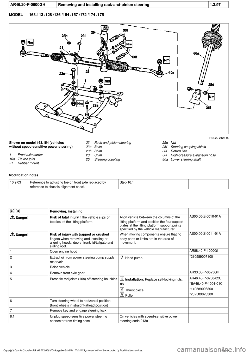
Shown on model 163.154 (vehicles
without speed-sensitive power steering)
1
Front axle carrier
10a
Tie rod joint
21
Rubber mount
25d
Nut
25f
Steering coupling shield
30f
Return line
30i
High-pressure expansion hose
80a
Lower steering shaft
23
Rack-and-pinion steering
23a
Bolts
23h
Shim
23i
Shim
25
Steering coupling
Modification notes
10.9.03
Reference to adjusting toe on front axle replaced by
reference to chassis alignment check
Step 16.1
Removing, installing
Danger!
Risk of fatal injury
if the vehicle slips or
topples off the lifting platform
Align vehicle between the columns of the
lifting platform and position the four support
plates
at the lifting platform support points
specified by the vehicle manufacturer.
AS00.00-Z-0010-01A
Danger!
Risk of injury
with
trapped or crushed
fingers when removing and installing or
aligning hoods, doors, trunk lid/tailgate and
sliding roof.
When moving components ensure that no
body parts or limbs are in the area of
movement.
AS00.00-Z-0011-01A
1
Open engine hood
AR88.40-P-1000GI
2
Extract oil from power steering pump supply
reservoir
Hand pump
*210589007100
3
Raise vehicle
4
Remove front axle gear
AR33.30-P-0525GH
5
Press tie rod joints (10a) off steering knuckles
Installation:
Replace self-locking nuts.
AR46.40-P-0200-02C
*BA46.40-P-1001-01C
Thrust piece
*140589006300
Puller
*202589023300
6
Turn steering wheel to horizontal position
(front wheels in straight-ahead position)
7
Remove key and engage steering lock
8.1
Unplug speed-sensitive power steering
connector from timing case
On vehicles with speed-sensitive power
steering code 213a
Copyright DaimlerChrysler AG 06.07.2006 CD-Ausgabe G/10/04 . This WIS print-out will not be recorde
d by Modification services.
Page 1
Page 3869 of 4133
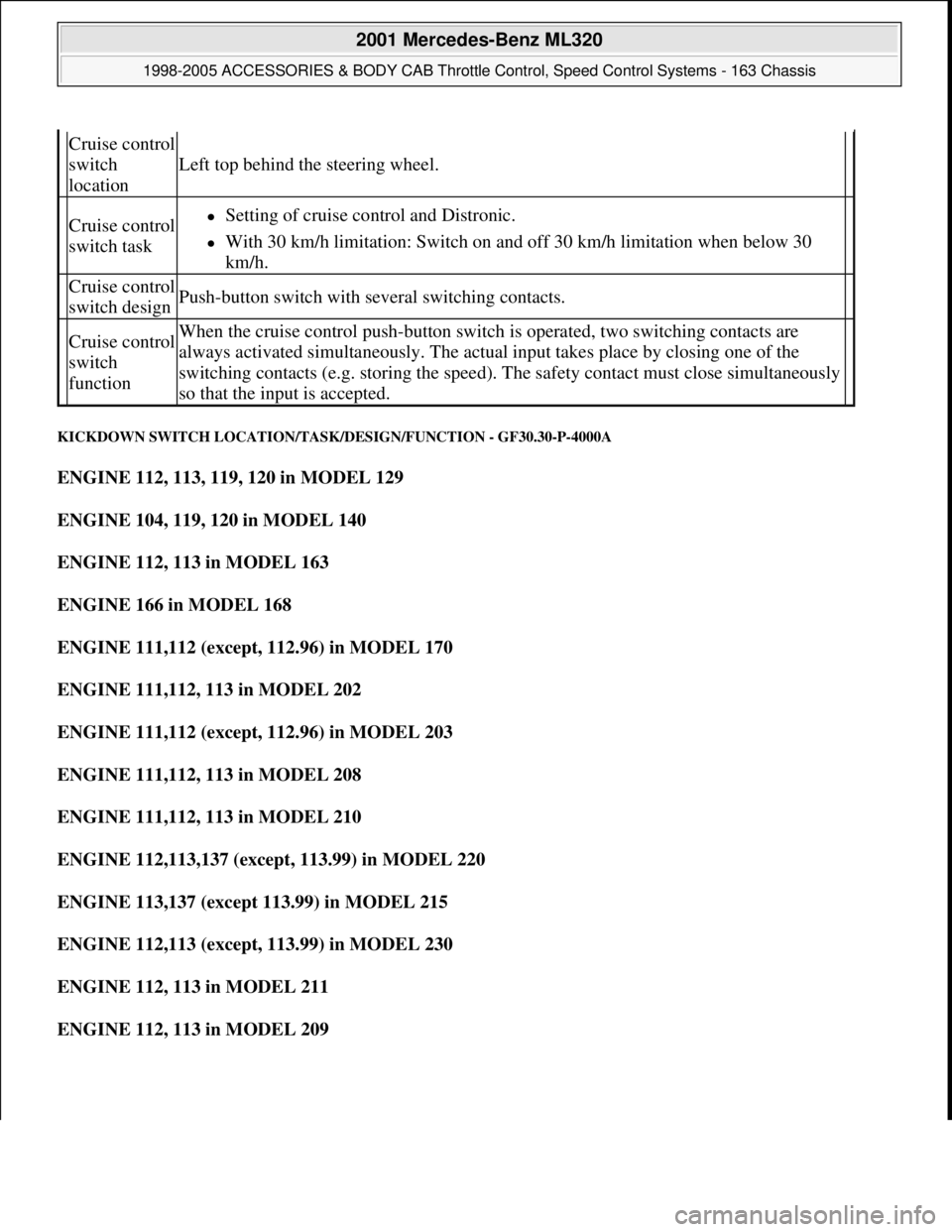
KICKDOWN SWITCH LOCATION/TASK/DESIGN/FUNCTION - GF30.30-P-4000A
ENGINE 112, 113, 119, 120 in MODEL 129
ENGINE 104, 119, 120 in MODEL 140
ENGINE 112, 113 in MODEL 163
ENGINE 166 in MODEL 168
ENGINE 111,112 (except, 112.96) in MODEL 170
ENGINE 111,112, 113 in MODEL 202
ENGINE 111,112 (except, 112.96) in MODEL 203
ENGINE 111,112, 113 in MODEL 208
ENGINE 111,112, 113 in MODEL 210
ENGINE 112,113,137 (except, 113.99) in MODEL 220
ENGINE 113,137 (except 113.99) in MODEL 215
ENGINE 112,113 (except, 113.99) in MODEL 230
ENGINE 112, 113 in MODEL 211
ENGINE 112, 113 in MODEL 209
Cruise control
switch
location
Left top behind the steering wheel.
Cruise control
switch taskSetting of cruise control and Distronic.
With 30 km/h limitation: Switch on and off 30 km/h limitation when below 30
km/h.
Cruise control
switch designPush-button switch with several switching contacts.
Cruise control
switch
functionWhen the cruise control push-button switch is operated, two switching contacts are
always activated simultaneously. The actual input takes place by closing one of the
switching contacts (e.g. storing the speed). The safety contact must close simultaneously
so that the input is accepted.
2001 Mercedes-Benz ML320
1998-2005 ACCESSORIES & BODY CAB Throttle Control, Speed Control Systems - 163 Chassis
me
Saturday, October 02, 2010 3:36:27 PMPage 29 © 2006 Mitchell Repair Information Company, LLC.
Page 3885 of 4133
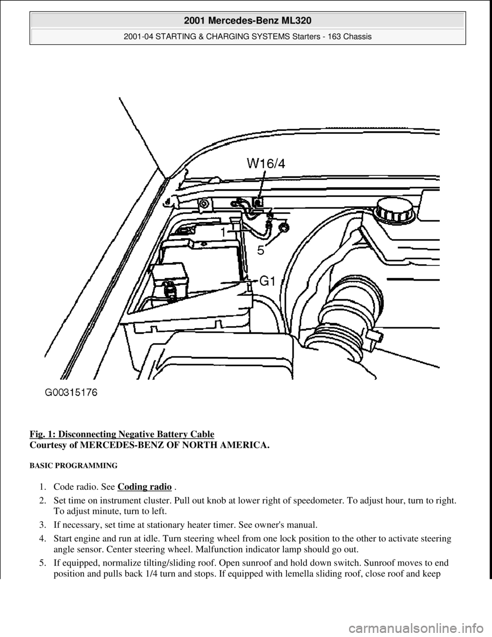
Fig. 1: Disconnecting Negative Battery Cable
Courtesy of MERCEDES-BENZ OF NORTH AMERICA.
BASIC PROGRAMMING
1. Code radio. See Coding radio .
2. Set time on instrument cluster. Pull out knob at lowe r right of speedometer. To adjust hour, turn to right.
To adjust minute, turn to left.
3. If necessary, set time at stationary heater timer. See owner's manual.
4. Start engine and run at idle. Turn steering wheel fr om one lock position to the other to activate steering
angle sensor. Center steering wheel. Ma lfunction indicator lamp should go out.
5. If equipped, normalize ti lting/sliding roof. Open sunroof and hold down switch. Sunroof moves to end
position and pulls back 1/4 turn and stops. If equipped with lemella slidin
g roof, close roof and keep
2001 Mercedes-Benz ML320
2001-04 STARTING & CHARGING SYSTEMS Starters - 163 Chassis
me
Saturday, October 02, 2010 3:19:47 PMPage 3 © 2006 Mitchell Repair Information Company, LLC.
Page 3896 of 4133
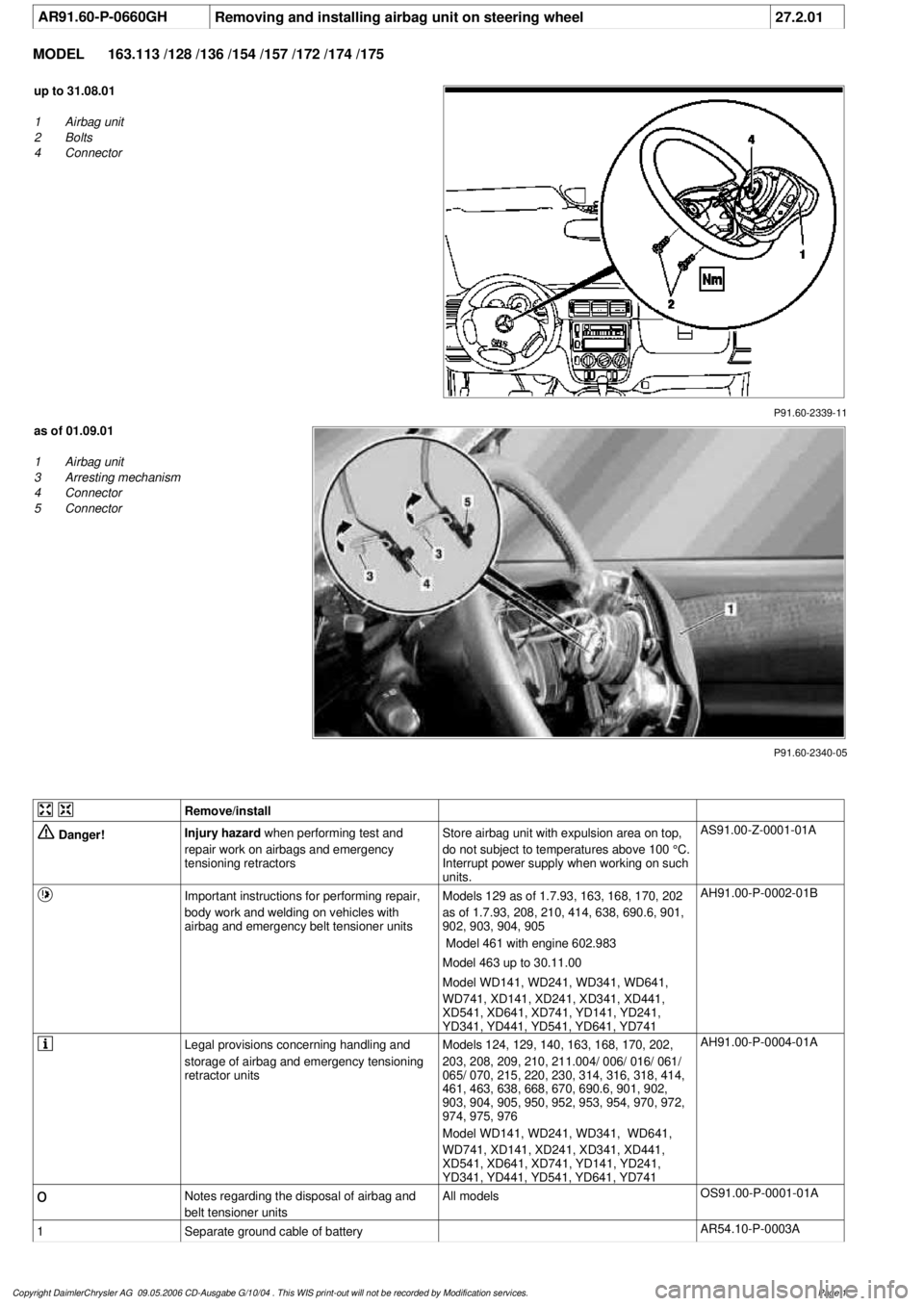
AR91.60-P-0660GH
Removing and installing airbag unit on steering wheel
27.2.01
MODEL
163.113 /128 /136 /154 /157 /172 /174 /175
P91.60-2339-11
up to 31.08.01
1
Airbag unit
2
Bolts
4
Connector
P91.60-2340-05
as of 01.09.01
1
Airbag unit
3
Arresting mechanism
4
Connector
5
Connector
Remove/install
Danger!
Injury hazard
when performing test and
repair work on airbags and emergency
tensioning retractorsStore airbag unit with expulsion area on top,
do not subject to temperatures above 100 °C.
Interrupt power supply when working on such
units.
AS91.00-Z-0001-01A
Important instructions for performing repair,
body work and welding on vehicles with
airbag and emergency belt tensioner units
Models 129 as of 1.7.93, 163, 168, 170, 202
as of 1.7.93, 208, 210, 414, 638, 690.6, 901,
902, 903, 904, 905
Model 461 with engine 602.983
Model 463 up to 30.11.00
Model WD141, WD241, WD341, WD641,
WD741, XD141, XD241, XD341, XD441,
XD541, XD641, XD741, YD141, YD241,
YD341, YD441, YD541, YD641, YD741
AH91.00-P-0002-01B
Legal provisions concerning handling and
storage of airbag and emergency tensioning
retractor units
Models 124, 129, 140, 163, 168, 170, 202,
203, 208, 209, 210, 211.004/ 006/ 016/ 061/
065/ 070, 215, 220, 230, 314, 316, 318, 414,
461, 463, 638, 668, 670, 690.6, 901, 902,
903, 904, 905, 950, 952, 953, 954, 970, 972,
974, 975, 976
Model WD141, WD241, WD341, WD641,
WD741, XD141, XD241, XD341, XD441,
XD541, XD641, XD741, YD141, YD241,
YD341, YD441, YD541, YD641, YD741
AH91.00-P-0004-01A
o
Notes regarding the disposal of airbag and
belt tensioner units
All models
OS91.00-P-0001-01A
1
Separate ground cable of battery
AR54.10-P-0003A
Copyright DaimlerChrysler AG 09.05.2006 CD-Ausgabe G/10/04 . This WIS print-out will not be recorde
d by Modification services.
Page 1