1997 MERCEDES-BENZ ML430 steering wheel
[x] Cancel search: steering wheelPage 1201 of 4133
Shift-Lock, Function
See SHIFT
-LOCK FUNCTION.
Park Pawl Interlock, Function
See PARK PAWL INTERLOCK, FUNCTION
.
Steering Lock Interlock, Function
See STEERING LOCK INTERLOCK, FUNCTION
.
Survey Of System Components, Automatic Transmission, Location/Task/Design/Function
See SURVEY OF SYSTEM COMPONENTS, AUTOMATIC TRANSMISSION,
LOCATION/TASK/DESIGN/FUNCTION.
Automatic Transmission, Function
Automatic transmission 722.6 is an electronically controlled 5-speed transmission with a lockup clutch in the
torque converter.
The ratios for the gear stages are achieved by three planetary gear sets. The 5th gear is designed with a step-up
ratio as an overdrive.
Shifting is initiated electronically. The gears are shifted by the corresponding combination of three
hydraulically actuated multi-disc clutches and two mechanical freewheels.
Basically automatic transmission 722.6 with electronic control offers the following advantages:
Reduced Fuel Consumption
Improved Shift Comfort
More Favorable Gear Steps As A Result Of 5 Gears
Enhanced Life And Reliability
Reduced Servicing Costs
The electrohydraulic control unit is bolted onto the bottom of the transmission housing. The end of the
transmission is formed by an oil pan made of sheet steel.
The oil pressure for the converter lockup clutch and center multiple-disc clutch is supplied via holes in the input
shaft. The oil pressure to the rear mulitiple-disc clutch is routed through the output shaft. The lubricating oil is
supplied and distributed by additional bore holes in both shafts. All bearing points of the gear sets as well as
freewheels and shift elements are supplied with lubricatin
g oil. NOTE: Transmission Without Touch Shift 722.6 In Model 163.
2001 Mercedes-Benz ML320
1998-03 AUTOMATIC TRANSMISSIONS Complete Transmissions - ML 320 - 722.662
me
Saturday, October 02, 2010 3:15:25 PMPage 32 © 2006 Mitchell Repair Information Company, LLC.
Page 1330 of 4133
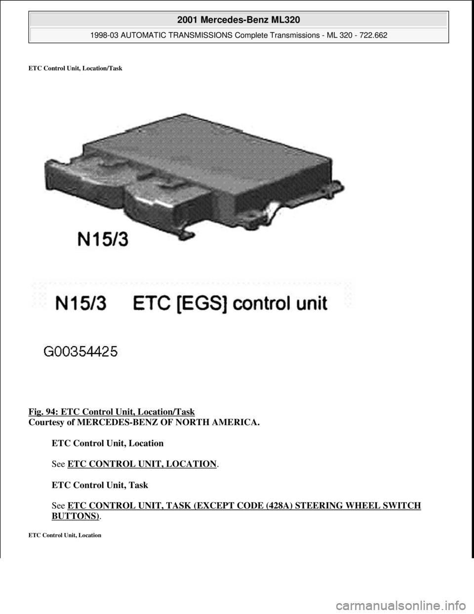
ETC Control Unit, Location/Task
Fig. 94: ETC Control Unit, Location/Task
Courtesy of MERCEDES-BENZ OF NORTH AMERICA.
ETC Control Unit, Location
See ETC CONTROL UNIT, LOCATION
.
ETC Control Unit, Task
See ETC CONTROL UNIT, TASK (EXCEPT CODE (428A) STEERING WHEEL SWITCH
BUTTONS).
ETC Control Unit, Location
2001 Mercedes-Benz ML320
1998-03 AUTOMATIC TRANSMISSIONS Complete Transmissions - ML 320 - 722.662
me
Saturday, October 02, 2010 3:15:27 PMPage 161 © 2006 Mitchell Repair Information Company, LLC.
Page 1501 of 4133
The Audio 30 APS does not have a number pad. For this reason, it is not possible to control the telephone over
the radio (see operating instructions).
On vehicles (as of approx. 07.99) with multifunction steering wheel (telephone control with keys on steering
wheel) this function is then also possible with the Audio 30 APS navigation system.
NOTES ON TRAFFIC PRO NAVIGATION SYSTEM - AH82.61-P-0002-01A
Models 129, 140, 163, 168, 170, 202, 208, 210
Customer information, installation position for GPS antenna
There are two different installation locations for the GSP antenna:
1. Standard GPS antenna from DaimlerChrysler on roof or trunk lid. This version offers the best reception
and is therefore preferable.
2. Use of magnetic antenna in vehicle passenger compartment. This version is part of the kit from the
Becker company and installation is described in Becker installation instructions.
Notes on installation of Becker GPS antenna
The GPS antenna can only be installed horizontally with a maximum deviation of 10° from horizontal.
The GPS antenna should always have an unobstructed view of the sky. Tinted windows can reduce the function
of the GPS antenna considerably.
When installing the GPS antenna always ensure that the arched surface of the antenna points upwards.
NOTES ON FIBER OPTIC CABLE - AH82.70-P-0001-02A
Model 129, 163, 168, 170, 202, 203, 208, 209, 210, 215, 220, 230, 414,
463.243/244/245/246/247/248/249/250/254/270/271/303/309/322/323/332/333/340/341
Illustrated on Model 202 sedan
2001 Mercedes-Benz ML320
1998-2005 ACCESSORIES & BODY, CAB Electrical System - Body - 163 Chassis
me
Saturday, October 02, 2010 3:30:04 PMPage 6 © 2006 Mitchell Repair Information Company, LLC.
Page 1503 of 4133
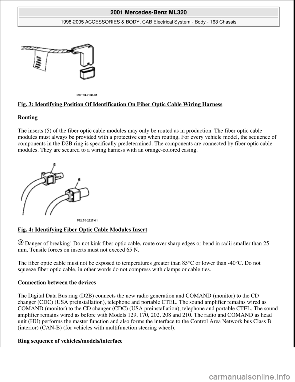
Fig. 3: Identifying Position Of Identification On Fiber Optic Cable Wiring Harness
Routing
The inserts (5) of the fiber optic cable modules may only be routed as in production. The fiber optic cable
modules must always be pr ovided with a protective cap when routing. For every vehicle model, the sequence of
components in the D2B ring is specifically predetermi ned. The components are connected by fiber optic cable
modules. They are secured to a wiring ha rness with an orange-colored casing.
Fig. 4: Identifying Fiber Optic Cable Modules Insert
Danger of breaking! Do not kink fiber optic cable, route over sharp edges or be nd in radii smaller than 25
mm. Tensile forces on inserts must not exceed 65 N.
The fiber optic cable must not be exposed to temperat ures greater than 85°C or lower than -40°C. Do not
squeeze fiber optic cable, in other words do not compress with clamps or cable ties.
Connection between the devices
The Digital Data Bus ring (D2B) connects the new ra dio generation and COMAND (monitor) to the CD
changer (CDC) (USA preinstallati on), telephone and portable CTEL. The sound amplifier remains wired as
COMAND (monitor) to the CD changer (CDC) (USA preinstallation), telephone and portable CTEL. The sound
amplifier remains wired as befo re with Models 129, 170, 202, 208 and 210. The radio and COMAND as head
unit (HU) performs the master function and also forms the interface to the Control Area Network bus Class B
(interior) (CAN-B) (for vehicles wi th multifunction steering wheel).
Ring sequence of vehi cles/models/interface
2001 Mercedes-Benz ML320
1998-2005 ACCESSORIES & BODY, CAB Electr ical System - Body - 163 Chassis
me
Saturday, October 02, 2010 3:30:04 PMPage 8 © 2006 Mitchell Repair Information Company, LLC.
Page 1569 of 4133
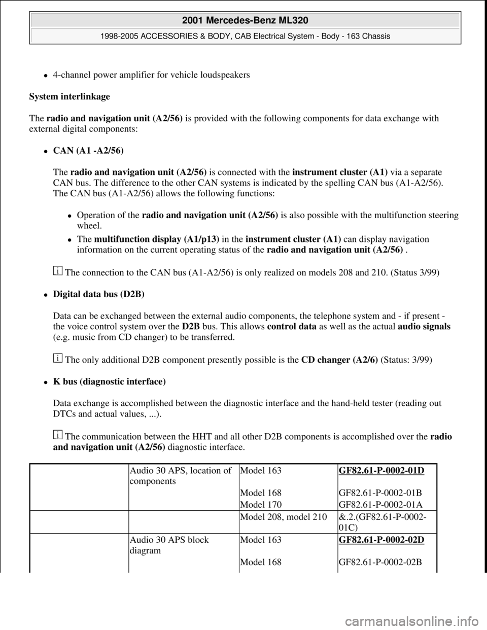
4-channel power amplifier for vehicle loudspeakers
System interlinkage
The radio and navigation unit (A2/56) is provided with the following components for data exchange with
external digital components:
CAN (A1 -A2/56)
The radio and navigation unit (A2/56) is connected with the instrument cluster (A1) via a separate
CAN bus. The difference to the other CAN systems is indicated by the spelling CAN bus (A1-A2/56).
The CAN bus (A1-A2/56) allows the following functions:
Operation of the radio and navigation unit (A2/56)is also possible with the multifunction steering
wheel.
The multifunction display (A1/p13) in the instrument cluster (A1) can display navigation
information on the current operating status of the radio and navigation unit (A2/56) .
The connection to the CAN bus (A1-A2/56) is only realized on models 208 and 210. (Status 3/99)
Digital data bus (D2B)
Data can be exchanged between the external audio components, the telephone system and - if present -
the voice control system over the D2B bus. This allows control data as well as the actual audio signals
(e.g. music from CD changer) to be transferred.
The only additional D2B component presently possible is the CD changer (A2/6) (Status: 3/99)
K bus (diagnostic interface)
Data exchange is accomplished between the diagnostic interface and the hand-held tester (reading out
DTCs and actual values, ...).
The communication between the HHT and all other D2B components is accomplished over the radio
and navigation unit (A2/56) diagnostic interface.
Audio 30 APS, location of
componentsModel 163GF82.61-P-0002-01D
Model 168GF82.61-P-0002-01B
Model 170GF82.61-P-0002-01A
Model 208, model 210&.2.(GF82.61-P-0002-
01C)
Audio 30 APS block
diagramModel 163GF82.61-P-0002-02D
Model 168GF82.61-P-0002-02B
2001 Mercedes-Benz ML320
1998-2005 ACCESSORIES & BODY, CAB Electrical System - Body - 163 Chassis
me
Saturday, October 02, 2010 3:30:05 PMPage 74 © 2006 Mitchell Repair Information Company, LLC.
Page 1671 of 4133
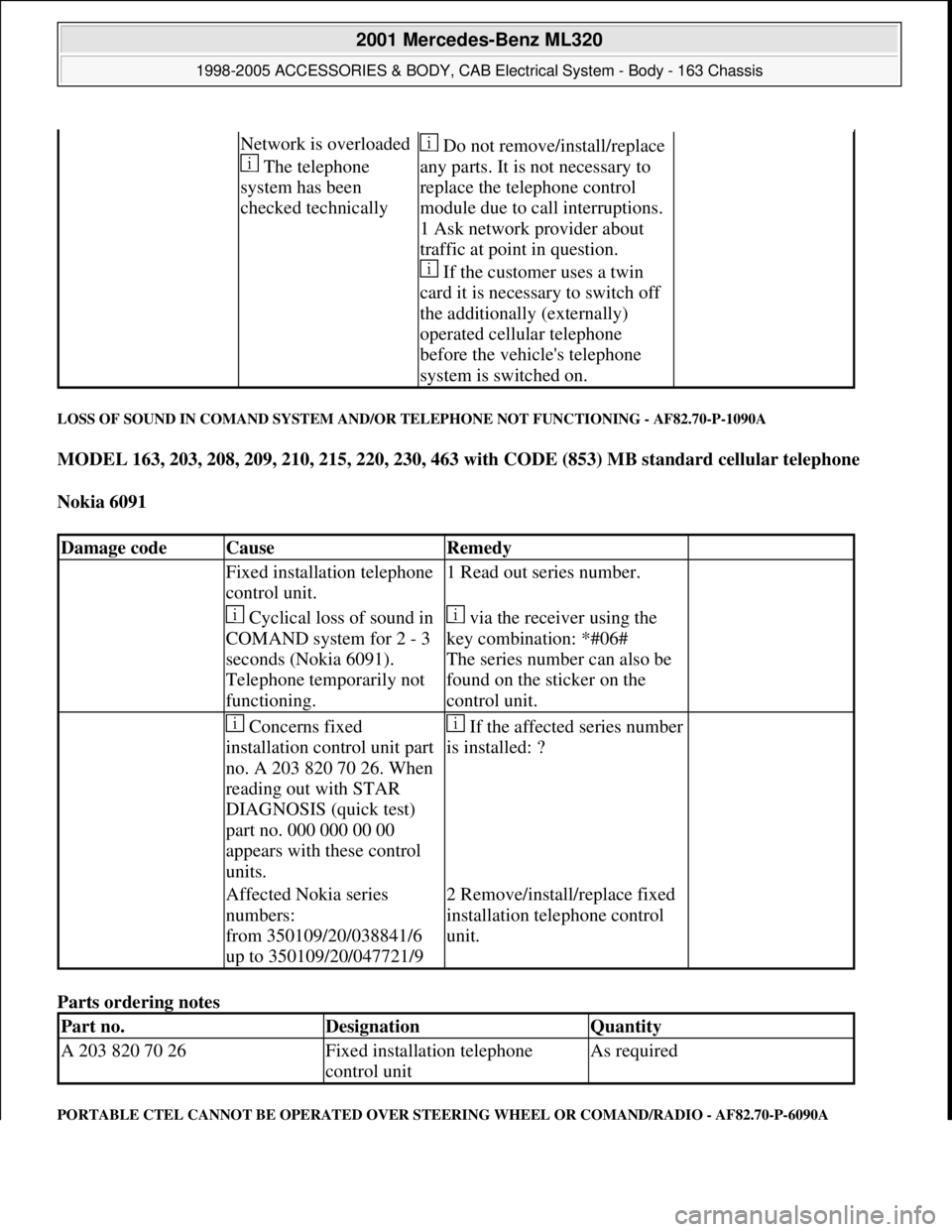
LOSS OF SOUND IN COMAND SYSTEM AND/OR TELEPHONE NOT FUNCTIONING - AF82.70-P-1090A
MODEL 163, 203, 208, 209, 210, 215, 220, 230, 463 with CODE (853) MB standard cellular telephone
Nokia 6091
Parts ordering notes
PORTABLE CTEL CANNOT BE OPERATED OVER STEERING WHEEL OR COMAND/RADIO - AF82.70-P-6090A
Network is overloaded
The telephone
system has been
checked technically Do not remove/install/replace
any parts. It is not necessary to
replace the telephone control
module due to call interruptions.
1 Ask network provider about
traffic at point in question.
If the customer uses a twin
card it is necessary to switch off
the additionally (externally)
operated cellular telephone
before the vehicle's telephone
system is switched on.
Damage codeCauseRemedy
Fixed installation telephone
control unit.1 Read out series number.
Cyclical loss of sound in
COMAND system for 2 - 3
seconds (Nokia 6091).
Telephone temporarily not
functioning. via the receiver using the
key combination: *#06#
The series number can also be
found on the sticker on the
control unit.
Concerns fixed
installation control unit part
no. A 203 820 70 26. When
reading out with STAR
DIAGNOSIS (quick test)
part no. 000 000 00 00
appears with these control
units.If the affected series number
is installed: ?
Affected Nokia series
numbers:
from 350109/20/038841/6
up to 350109/20/047721/92 Remove/install/replace fixed
installation telephone control
unit.
Part no.DesignationQuantity
A 203 820 70 26Fixed installation telephone
control unitAs required
2001 Mercedes-Benz ML320
1998-2005 ACCESSORIES & BODY, CAB Electrical System - Body - 163 Chassis
me
Saturday, October 02, 2010 3:30:07 PMPage 176 © 2006 Mitchell Repair Information Company, LLC.
Page 1829 of 4133
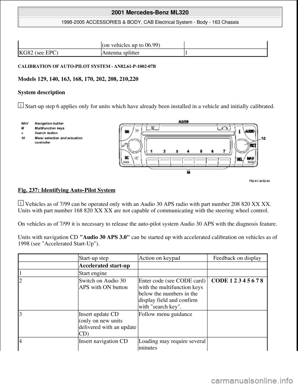
CALIBRATION OF AUTO-PILOT SYSTEM - AN82.61-P-1002-07B
Models 129, 140, 163, 168, 170, 202, 208, 210,220
System description
Start-up step 6 applies only for units which have already been installed in a vehicle and initially calibrated.
Fig. 237: Identifying Auto
-Pilot System
Vehicles as of 7/99 can be operated only with an Audio 30 APS radio with part number 208 820 XX XX.
Units with part number 168 820 XX XX are not capable of communicating with the steering wheel control.
On vehicles as of 7/99 it is necessary to release the auto-pilot system Audio 30 APS with the diagnosis feature.
Units with navigation CD "Audio 30 APS 3.0" can be started up with accelerated calibration on vehicles as of
1998 (see "Accelerated Start-Up").
(on vehicles up to 06.99)
KG82 (see EPC)Antenna splitter1
Start-up stepAction on keypadFeedback on display
Accelerated start-up
1Start engine
2Switch on Audio 30
APS with ON buttonEnter code (see CODE card)
with the multifunction keys
below the numbers in the
display field and confirm
with "search key".CODE 1 2 3 4 5 6 7 8
3Insert update CD
(only on new units
delivered with an update
CD)Follow menu guidance
4Insert navigation CDLoading may require several
minutes
2001 Mercedes-Benz ML320
1998-2005 ACCESSORIES & BODY, CAB Electrical System - Body - 163 Chassis
me
Saturday, October 02, 2010 3:30:11 PMPage 334 © 2006 Mitchell Repair Information Company, LLC.
Page 2042 of 4133

3. Normalize side power windows. See NORMALIZING POWER WINDOWS .
4. Start engine and run at idle. Turn steering wheel from one lock position to the other to activate steering
angle sensor. Center steering wheel. Message "EI. STAB. PROGRAM GO TO GARAGE" should erase
from multifunction display panel.
5. If equipped, normalize tilting/sliding roof. See NORMALIZING TILTING/SLIDING ROOF
.
6. If equipped, normalize memory power seats, steering column and outside mirror if components are
installed. See NORMALIZING MEMORY POWER SEATS, STEERING COLUMN & OUTSIDE
MIRROR .
Normalizing Power Windows
1. Completely close each window with manual switch. Hold switch in closed position for .3 second.
2. Repeat procedure for each power window.
Normalizing Memory Power Seats, Steering Column & Outside Mirror
1. Using manual switch, move seat to each end position and hold for .3 second. Repeat procedure for each
switch except rear stop of backrest.
2. Repeat procedure for end positions of steering wheel and outside mirrors.
Normalizing Tilting/Sliding Roof
Open roof with SR switch until mechanical stop is reached. Continue to press switch for .5 seconds.
Setting Time
1. Use bottom left button on steering wheel to scroll through menus on instrument cluster to "Settings"
menu.
2. Move selection marker with + or - button to "Time" submenu.
3. Press up or down arrows to "Clock, hours" setting. Confirm selection marker is on the hour setting.
4. Press + or - to set hour. Press reset knob in instrument cluster to confirm.
5. Move selection marker with + or - button to "Time" submenu.
6. Press up or down arrows to "Clock, minutes" setting. Confirm selection marker is on the minutes setting.
7. Press + or - to set minute. Press reset knob in instrument cluster to confirm.
TESTING
If generator malfunctions, check for Diagnostic Trouble Codes (DTCs) in Motor Electronics Sequential Fuel
Injection (ME-SFI) system. See appropriate SELF-DIAGNOSTICS article in ENGINE PERFORMANCE. If
cause of generator malfunction is not engine performance related, replace generator.
RETRIEVING & ERASING DIAGNOSTIC TROUBLE CODES
NOTE: Before replacing any component that scan tool suggests are faulty, ensure that
all wiring connections and harness connectors are okay. Ensure that power and
2001 Mercedes-Benz ML320
2001-04 STARTING & CHARGING SYSTEMS Generators & Regulators - 163 Chassis
me
Saturday, October 02, 2010 3:20:32 PMPage 8 © 2006 Mitchell Repair Information Company, LLC.