Page 1898 of 4133
Fig. 326: Identifying CAN Bus Adapter And Self-Tapping Screws
4. Disconnect standard wiring harness (2) fr om transfer case control module (N78).
5. Connect CAN bus (9) wiri ng harness between transfer case cont rol module (N78) and standard wiring
harness (2).
6. Route CAN bus (6) lead on fan duct.
Fig. 327: Identifying Transfer Case Cont rol Module And CAN Bus Wiring Harness
7. Route connector (8) for TrafficStar wiring harness (4) from radio shaft along fan duct to center console.
Fig. 328: Identifying Trafficstar Wiring Harness And Connector
Steps 8-10 apply only for vehicl es with manual transmission
2001 Mercedes-Benz ML320
1998-2005 ACCESSORIES & BODY, CAB Electr ical System - Body - 163 Chassis
me
Saturday, October 02, 2010 3:30:12 PMPage 403 © 2006 Mitchell Repair Information Company, LLC.
Page 1899 of 4133
8. Separate green lead (gn) from CAN bus adapter connector (8).
9. Tie TrafficStar (4) wiring harness on at height of shift gate and pull out green lead (gn).
Fig. 329: Identifying CAN Bus Adapter Connector And Trafficstar Wiring Harness
10. Route green lead (gn) to back-up lamp switch (S16/2).
11. Connect lower gray lead (gr) from connector with assignment 2 for back-up lamp switch (S16/2) to green
lead (gn) using solder connector.
The connector for the back-up lamp switch (S16/2) has two gray leads, the lower of the two leads is
for the switched back-up lamp signal.
Fig. 330: Identifying Back
-Up Lamp Switch And Green Lead
12. Connect connector (8) and lead (6) to CAN bus adapter (5).
13. Install center console.
2001 Mercedes-Benz ML320
1998-2005 ACCESSORIES & BODY, CAB Electrical System - Body - 163 Chassis
me
Saturday, October 02, 2010 3:30:12 PMPage 404 © 2006 Mitchell Repair Information Company, LLC.
Page 1906 of 4133
Fig. 336: Identifying Trafficstar Navigation System Components
Notes on TrafficStar
navigation systemModels 129, 140, 163,
168, 170, 202, 208, 210AH82.61-P-0001-03A
Removal
1Disconnect ground lead
from battery
AR54.10-P-0003A
2Remove radio
AR82.60-P-7502EA
3Remove center console
AR68.20-P-2000GH
4Remove cover below
right instrument panel
AR68.10-P-1520GH
5Remove paneling from
A-pillar Only in area of
instrument panel
AR68.30-P-4050GH
Installation
6Retrofit TrafficStar GPS
antenna on instrument
panel AZ82.61-P-0001-01F
7Connect TrafficStar radio Only on vehicles with AZ82.61-P-0001-02G
2001 Mercedes-Benz ML320
1998-2005 ACCESSORIES & BODY, CAB Electrical System - Body - 163 Chassis
me
Saturday, October 02, 2010 3:30:13 PMPage 411 © 2006 Mitchell Repair Information Company, LLC.
Page 1911 of 4133
Fig. 344: Identifying CAN Bus Adapter
11. Install white (ws) and blue (bl) fuse on connector for transfer case control module (N78) from CAN bus
wiring harness (9) as shown in figure.
Fig. 345: Identifying Transfer Case Cont rol Module And CAN Bus Wiring Harness
12. Disconnect connector from transfer case control module (N78) and connect CAN bus wiring harness (9)
between transfer case control module (N78) and standard wiring harness.
Illustrated without center console
13. Connect CAN connector (6) from CAN bus wiring harnes s (9) to CAN bus adapter (5).
Fig. 346: Identifying CAN Bu s Adapter And CAN Connector
2001 Mercedes-Benz ML320
1998-2005 ACCESSORIES & BODY, CAB Electr ical System - Body - 163 Chassis
me
Saturday, October 02, 2010 3:30:13 PMPage 416 © 2006 Mitchell Repair Information Company, LLC.
Page 1913 of 4133

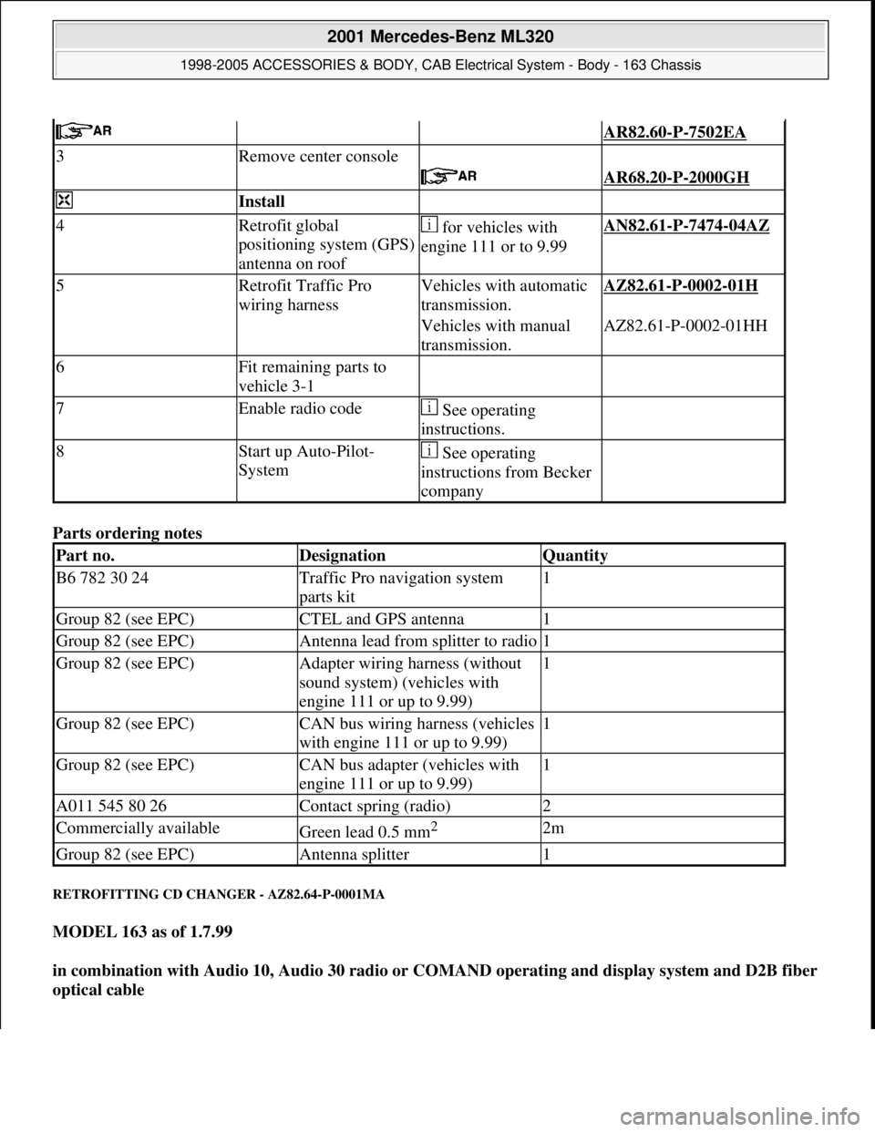
Parts ordering notes
RETROFITTING CD CHANGER - AZ82.64-P-0001MA
MODEL 163 as of 1.7.99
in combination with Audio 10, Audio 30 radio or COMAND operating and display system and D2B fiber
optical cable
AR82.60-P-7502EA
3Remove center console
AR68.20-P-2000GH
Install
4Retrofit global
positioning system (GPS)
antenna on roof for vehicles with
engine 111 or to 9.99AN82.61-P-7474-04AZ
5Retrofit Traffic Pro
wiring harnessVehicles with automatic
transmission.AZ82.61-P-0002-01H
Vehicles with manual
transmission.AZ82.61-P-0002-01HH
6Fit remaining parts to
vehicle 3-1
7Enable radio code See operating
instructions.
8Start up Auto-Pilot-
System See operating
instructions from Becker
company
Part no.DesignationQuantity
B6 782 30 24Traffic Pro navigation system
parts kit1
Group 82 (see EPC)CTEL and GPS antenna1
Group 82 (see EPC)Antenna lead from splitter to radio1
Group 82 (see EPC)Adapter wiring harness (without
sound system) (vehicles with
engine 111 or up to 9.99)1
Group 82 (see EPC)CAN bus wiring harness (vehicles
with engine 111 or up to 9.99)1
Group 82 (see EPC)CAN bus adapter (vehicles with
engine 111 or up to 9.99)1
A011 545 80 26Contact spring (radio)2
Commercially availableGreen lead 0.5 mm2 2m
Group 82 (see EPC)Antenna splitter1
2001 Mercedes-Benz ML320
1998-2005 ACCESSORIES & BODY, CAB Electrical System - Body - 163 Chassis
me
Saturday, October 02, 2010 3:30:13 PMPage 418 © 2006 Mitchell Repair Information Company, LLC.
Page 1921 of 4133
Fig. 361: Identifying Console And Screw
5. Route tieouts (A and B) for cellul ar telephone wiring harness (2) and an tenna lead (17) to console (12)
and connect.
6. Form excess lengths of the connection cables into a loop and secure with Velcro (18).
7. Route cables for connection plug (5) behi nd the center console to the right seat.
Fig. 362: Identifying Cellular Telepho ne Wiring Harness And Antenna Lead
8. Insert console (12) into mount holes on air condi tioning control module using locating pin and align at
instrument panel.
9. Mark hole for screw (13) and drill with 2.5 mm dia. bit.
When drilling in instrument pa nel do not damage parts behind.
10. Screw console (12) to instru ment panel with screw (13).
2001 Mercedes-Benz ML320
1998-2005 ACCESSORIES & BODY, CAB Electr ical System - Body - 163 Chassis
me
Saturday, October 02, 2010 3:30:13 PMPage 426 © 2006 Mitchell Repair Information Company, LLC.
Page 1938 of 4133
Fig. 396: Identifying D-Network Cell Phone Components
Removal
1Disconnect ground cable
of battery
AR54.10-P-0003A
2Remove radio
3Remove stowage
compartment below radio
4Remove stowage
compartment in center
armrest
5Remove wooden cover
from shift lever
6Remove cover below
right instrument panel
7Remove A-pillar paneling
at top right
8Tie out D-net antenna
lead Tied back in radio
shaft.
Install
9Install holder on
telephone console AZ82.70-P-0001-01A
10Installing hands free AZ82.70-P-0001-02A
2001 Mercedes-Benz ML320
1998-2005 ACCESSORIES & BODY, CAB Electrical System - Body - 163 Chassis
me
Saturday, October 02, 2010 3:30:14 PMPage 443 © 2006 Mitchell Repair Information Company, LLC.
Page 1945 of 4133

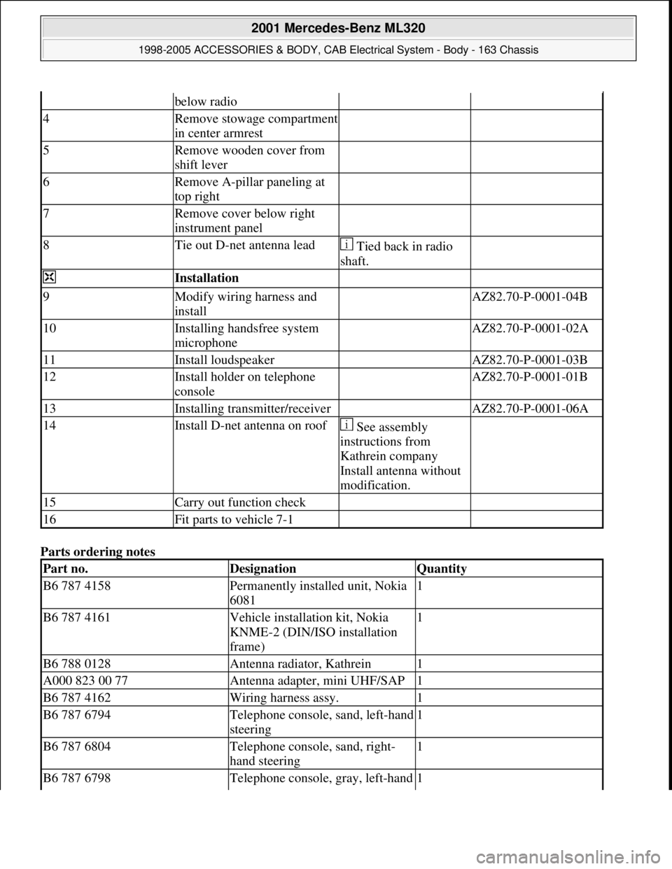
Parts ordering notes
below radio
4Remove stowage compartment
in center armrest
5Remove wooden cover from
shift lever
6Remove A-pillar paneling at
top right
7Remove cover below right
instrument panel
8Tie out D-net antenna lead Tied back in radio
shaft.
Installation
9Modify wiring harness and
install AZ82.70-P-0001-04B
10Installing handsfree system
microphone AZ82.70-P-0001-02A
11Install loudspeaker AZ82.70-P-0001-03B
12Install holder on telephone
console AZ82.70-P-0001-01B
13Installing transmitter/receiver AZ82.70-P-0001-06A
14Install D-net antenna on roof See assembly
instructions from
Kathrein company
Install antenna without
modification.
15Carry out function check
16Fit parts to vehicle 7-1
Part no.DesignationQuantity
B6 787 4158Permanently installed unit, Nokia
60811
B6 787 4161Vehicle installation kit, Nokia
KNME-2 (DIN/ISO installation
frame)1
B6 788 0128Antenna radiator, Kathrein1
A000 823 00 77Antenna adapter, mini UHF/SAP1
B6 787 4162Wiring harness assy.1
B6 787 6794Telephone console, sand, left-hand
steering1
B6 787 6804Telephone console, sand, right-
hand steering1
B6 787 6798Telephone console, gray, left-hand 1
2001 Mercedes-Benz ML320
1998-2005 ACCESSORIES & BODY, CAB Electrical System - Body - 163 Chassis
me
Saturday, October 02, 2010 3:30:14 PMPage 450 © 2006 Mitchell Repair Information Company, LLC.