Page 1132 of 4133

328 IndexK
Key
Global locking 89
Global unlocking 89
Loss of 90
Positions in steering lock 33
Remote control with folding key 88
Unlocking liftgate 89
Unlocking the driver’s door, fuel filler
flap 89
Key positions in steering lock 33
Key, Mechanical 261
Key, Remote control
Unlocking with 32
Kickdown 123, 313
L
Labels, identification 292
Lamp bulbs, exterior 266
Lamps, exterior
Front 266
Rear 267Lamps, indicator and warning
4-ETS 251, 252
ABS 242
Adjustable steering column 253
AIRBAG OFF 63, 243
BAS 78, 245, 246, 247
Battery indicator lamp 254
Brake pad wear 254
Brakes 244
CHECK ENGINE 248
Coolant 249
EBP 245
Engine diagnostics 248
ESP 245, 246, 247, 251
Front fog lamps 253
Fuel reserve 252
Low engine oil level 253
LOW RANGE 252
Low washer system fluid level 253
Seat belts 253
Service indicator 232
SRS 255
Turn signals 25LATCH child seat anchors 72
LATCH child seat mounts 72
Layout of poly-V-belt drive 293
Leather upholstery
Cleaning 239
Lever
For cruise control 150
License plate lamps
Replacing bulbs 267, 271
Liftgate
Closing 92
Opening 89, 91
Opening from inside 91
Opening from outside 91
Light alloy wheels
Cleaning 238
Lighter
Rear center console 169
Lighter see cigarette lighter 168
Page 1337 of 4133
Fig. 98: Electronic Selector Lever Module Control Module
Courtesy of MERCEDES-BENZ OF NORTH AMERICA.
Electronic Selector Lever Module Control Module, Location
The electronic selector lever module control module (n15/5) is located in the center console of the
vehicle. See Fig. 98
.
Electronic Selector Lever Module Control Module, Task
See ELECTRONIC SELECTOR LEVER MODULE CONTROL MODULE, TASK
.
Electronic Selector Lever Module Control Module, Design
See ELECTRONIC SELECTOR LEVER MODULE CONTROL MODULE, DESIGN
.
2001 Mercedes-Benz ML320
1998-03 AUTOMATIC TRANSMISSIONS Complete Transmissions - ML 320 - 722.662
me
Saturday, October 02, 2010 3:15:27 PMPage 168 © 2006 Mitchell Repair Information Company, LLC.
Page 1425 of 4133
Fig. 143: Floor Shift (Without Touch Shift)
Courtesy of MERCEDES-BENZ OF NORTH AMERICA.
Floor Shift, Location
The floor shift is located in the center console of the vehicle. See Fig. 143
.
Floor Shift, Task
The floor shift is the central control for the driver to influence the shift program of the automatic
transmission.
Floor Shift, Design
See FLOOR SHIFT, DESIGN
.
Floor Shift, Function
See FLOOR SHIFT, FUNCTION
.
Floor Shift, Design
2001 Mercedes-Benz ML320
1998-03 AUTOMATIC TRANSMI SSIONS Complete Transmissions - ML 320 - 722.662
me
Saturday, October 02, 2010 3:15:29 PMPage 256 © 2006 Mitchell Repair Information Company, LLC.
Page 1431 of 4133
Fig. 147: Floor Shift (With Touch Shift)
Courtesy of MERCEDES-BENZ OF NORTH AMERICA.
Floor Shift, Location
The floor shift is located in the center console of the vehicle. See Fig. 147
.
Floor Shift, Task
The floor shift is the central control for the driver to influence the shift program of the automatic
transmission.
Floor Shift, Design
See FLOOR SHIFT, DESIGN
.
Floor Shift, Function
See FLOOR SHIFT, FUNCTION
.
2001 Mercedes-Benz ML320
1998-03 AUTOMATIC TRANSMISSIONS Complete Transmissions - ML 320 - 722.662
me
Saturday, October 02, 2010 3:15:29 PMPage 262 © 2006 Mitchell Repair Information Company, LLC.
Page 1654 of 4133

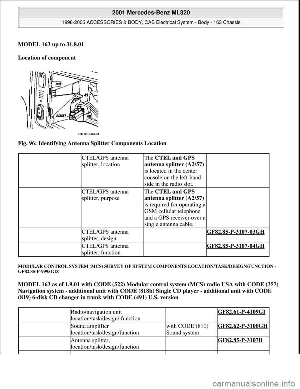
MODEL 163 up to 31.8.01
Location of component
Fig. 96: Identifying Antenna Splitter Components Location
MODULAR CONTROL SYSTEM (MCS) SURVEY OF SYSTEM COMPONENTS LOCATION/TASK/DESIGN/FUNCTION -
GF82.85-P-9995GIZ
MODEL 163 as of 1.9.01 with CODE (522) Modular control system (MCS) radio USA with CODE (357)
Navigation system - additional unit with CODE (818b) Single CD player - additional unit with CODE
(819) 6-disk CD changer in trunk with CODE (491) U.S. version
CTEL/GPS antenna
splitter, locationThe CTEL and GPS
antenna splitter (A2/57)
is located in the center
console on the left-hand
side in the radio slot.
CTEL/GPS antenna
splitter, purposeThe CTEL and GPS
antenna splitter (A2/57)
is required for operating a
GSM cellular telephone
and a GPS receiver over a
single antenna cable.
CTEL/GPS antenna
splitter, design GF82.85-P-3107-03GH
CTEL/GPS antenna
splitter, function GF82.85-P-3107-04GH
Radio/navigation unit
location/task/design/ function GF82.61-P-4109GI
Sound amplifier
location/task/design/functionwith CODE (810)
Sound systemGF82.62-P-3100GH
Antenna splitter,
location/task/design/function GF82.85-P-3107B
2001 Mercedes-Benz ML320
1998-2005 ACCESSORIES & BODY, CAB Electrical System - Body - 163 Chassis
me
Saturday, October 02, 2010 3:30:06 PMPage 159 © 2006 Mitchell Repair Information Company, LLC.
Page 1664 of 4133
![MERCEDES-BENZ ML430 1997 Complete Repair Manual MODEL 163 with CODE (259) Radio Premium with Bose sound system
Parts ordering notes
PROGRAM CHANGE ALTHOUGH RDS [RADIO DATA SYSTEM] AND REGIONALIZATION ARE SWITCHED ON -
AF82.60-P-1062A
MODEL 129, MERCEDES-BENZ ML430 1997 Complete Repair Manual MODEL 163 with CODE (259) Radio Premium with Bose sound system
Parts ordering notes
PROGRAM CHANGE ALTHOUGH RDS [RADIO DATA SYSTEM] AND REGIONALIZATION ARE SWITCHED ON -
AF82.60-P-1062A
MODEL 129,](/manual-img/4/57307/w960_57307-1663.png)
MODEL 163 with CODE (259) Radio Premium with Bose sound system
Parts ordering notes
PROGRAM CHANGE ALTHOUGH RDS [RADIO DATA SYSTEM] AND REGIONALIZATION ARE SWITCHED ON -
AF82.60-P-1062A
MODEL 129, 140, 163, 168, 170, 171, 202, 203, 208, 209, 210, 211, 215, 220, 230, 463 with RDS radio
Damage codeCauseRemedy
Speaker wires picking up
interference noise from
surrounding wiring1 Remove radioAR82.60-P-7502EA
2 Remove upper center
console storage
compartment
3 Remove lower dash
panel below steering
columnAR68.10-P-1500GH
4 Install sound system
jumper harness
AF82.60-P-1010-01AG
5 Reinstall in opposite
order
Part no.DesignationQuantity
163 540 98 05Jumper harness for Bose sound
system1
Damage codeCauseRemedy
Station change without
obvious cause.
Some radio stations
which had originally
transmitted regional
identification have been
transmitting the RDS
signals without regional
identification for some
time.
Without regional
identification it is no
longer possible to
separate stations with the
same station name which
transmit different
programs.1 Point out the facts to
the customer.
Do not replace any
devices, state of the art
engineering.
2001 Mercedes-Benz ML320
1998-2005 ACCESSORIES & BODY, CAB Electrical System - Body - 163 Chassis
me
Saturday, October 02, 2010 3:30:06 PMPage 169 © 2006 Mitchell Repair Information Company, LLC.
Page 1815 of 4133

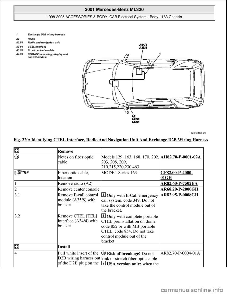
Fig. 220: Identifying CTEL Interface, Radio And Navigation Unit And Exchange D2B Wiring Harness
Remove
Notes on fiber optic
cableModels 129, 163, 168, 170, 202,
203, 208, 209,
210,215,220,230,463AH82.70-P-0001-02A
Fiber optic cable,
locationMODEL Series 163GF82.00-P-4000-
01GH
1Remove radio (A2) AR82.60-P-7502EA
2Remove center console AR68.20-P-2000GH
3.1Remove E-call control
module (A35/8) with
bracket Only with E-Call emergency
call system, code 349. Do not
take the control module out of
the bracket.AR82.95-P-0008GH
3.2Remove CTEL [TEL]
interface (A34/4) with
bracket Only with complete portable
CTEL preinstallation on dome
code 852 or with MB portable
CTEL, code 854. Do not take
control module out of the
bracket.
Install
4Pull white insert of the
D2B wiring harness out
of the D2B plug on the Risk of breakage! Do not
kink or stretch fiber optic cable
USA version only: when the AR82.70-P-0004-01A
2001 Mercedes-Benz ML320
1998-2005 ACCESSORIES & BODY, CAB Electrical System - Body - 163 Chassis
me
Saturday, October 02, 2010 3:30:10 PMPage 320 © 2006 Mitchell Repair Information Company, LLC.
Page 1817 of 4133

Front seats
Seat belts/emergency tensioning retractors
MAINTENANCE
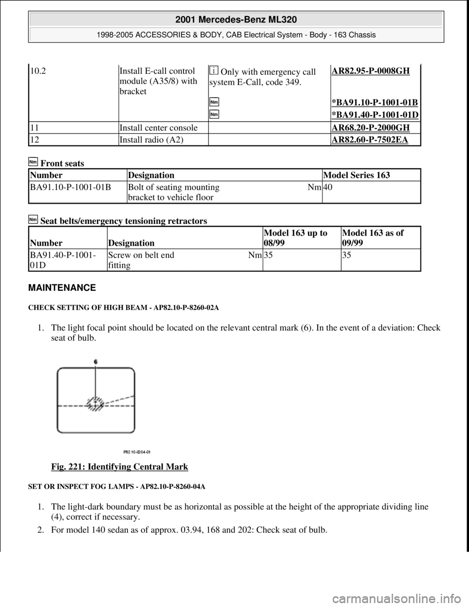
CHECK SETTING OF HIGH BEAM - AP82.10-P-8260-02A
1. The light focal point should be located on the relevant central mark (6). In the event of a deviation: Check
seat of bulb.
Fig. 221: Identifying Central Mark
SET OR INSPECT FOG LAMPS - AP82.10-P-8260-04A
1. The light-dark boundary must be as horizontal as possible at the height of the appropriate dividing line
(4), correct if necessary.
2. For model 140 sedan as of approx. 03.94, 168 and 202: Check seat of bulb.
10.2Install E-call control
module (A35/8) with
bracket Only with emergency call
system E-Call, code 349.AR82.95-P-0008GH
*BA91.10-P-1001-01B
*BA91.40-P-1001-01D
11Install center console AR68.20-P-2000GH
12Install radio (A2) AR82.60-P-7502EA
NumberDesignationModel Series 163
BA91.10-P-1001-01BBolt of seating mounting
bracket to vehicle floorNm40
NumberDesignation
Model 163 up to
08/99Model 163 as of
09/99
BA91.40-P-1001-
01DScrew on belt end
fittingNm3535
2001 Mercedes-Benz ML320
1998-2005 ACCESSORIES & BODY, CAB Electrical System - Body - 163 Chassis
me
Saturday, October 02, 2010 3:30:10 PMPage 322 © 2006 Mitchell Repair Information Company, LLC.