Page 1824 of 4133
Fig. 230: Identifying CAN Bus Adapter And Adapter Wiring Harness
7. Position CAN bus adapter mount on st rut of center console and mark hole pattern (arrows) as shown in
figure.
8. Drill 6.2 mm dia. mounting holes.
Fig. 231: Locating Hole Pattern
9. Fasten CAN bus adapter (5) with self-tappi ng screws from CAN bus adapter parts kit.
Fig. 232: Identifying CAN Bus Adapter
10. Install white (ws) and blue (bl) fuse on transfer case control module (N78) from CAN bus wiring harness
(9) as shown in figure.
2001 Mercedes-Benz ML320
1998-2005 ACCESSORIES & BODY, CAB Electr ical System - Body - 163 Chassis
me
Saturday, October 02, 2010 3:30:10 PMPage 329 © 2006 Mitchell Repair Information Company, LLC.
Page 1825 of 4133

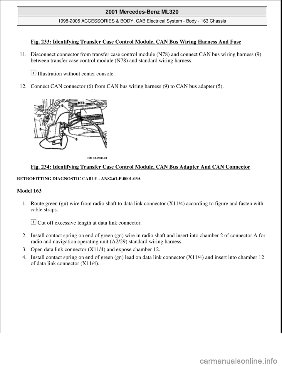
Fig. 233: Identifying Transfer Case Control Module, CAN Bus Wiring Harness And Fuse
11. Disconnect connector from transfer case control module (N78) and connect CAN bus wiring harness (9)
between transfer case control module (N78) and standard wiring harness.
Illustration without center console.
12. Connect CAN connector (6) from CAN bus wiring harness (9) to CAN bus adapter (5).
Fig. 234: Identifying Transfer Case Control Module, CAN Bus Adapter And CAN Connector
RETROFITTING DIAGNOSTIC CABLE - AN82.61-P-0001-03A
Model 163
1. Route green (gn) wire from radio shaft to data link connector (X11/4) according to figure and fasten with
cable straps.
Cut off excessive length at data link connector.
2. Install contact spring on end of green (gn) wire in radio shaft and insert into chamber 2 of connector A for
radio and navigation operating unit (A2/29) standard wiring harness.
3. Open data link connector (X11/4) and expose chamber 12.
4. Install contact spring on end of green (gn) lead on data link connector (X11/4) and insert into chamber 12
of data link connector (X11/4).
2001 Mercedes-Benz ML320
1998-2005 ACCESSORIES & BODY, CAB Electrical System - Body - 163 Chassis
me
Saturday, October 02, 2010 3:30:10 PMPage 330 © 2006 Mitchell Repair Information Company, LLC.
Page 1827 of 4133
Fig. 236: Identifying Retrofit Navigation System Audio 30 APS Components
Notes on assignment for
radio connectorModel 163AH82.61-P-0001-05A
Notes on telephone
operation with Audio 30
APS navigation systemModel 129, 163, 168,
170, 202, 208, 210AH82.61-P-0001-06A
Removal
1Disconnect ground cable
of battery
AR54.10-P-0003A
2Remove radio The Audio 30 APS
radio is installed.
AR82.60-P-7502EA
3Remove center console
AR68.20-P-2000GH
4Remove cover below
instrument panel on left On vehicles up to
06/99
AR68.10-P-1500GH
5Remove diagnostic
socket On vehicles up to
06/99
Install
6Retrofit global position AN82.61-P-7474-04AZ
2001 Mercedes-Benz ML320
1998-2005 ACCESSORIES & BODY, CAB Electrical System - Body - 163 Chassis
me
Saturday, October 02, 2010 3:30:10 PMPage 332 © 2006 Mitchell Repair Information Company, LLC.
Page 1833 of 4133
Fig. 239: Identifying Antenna Diplexer, Antenna Line And GPS Antenna Lead
RETROFIT FIBER OPTIC CABLE WIRING HARNESS - AN82.70-P-0002-01GH
Connection diagram of fiber optic cable
1. Prepare fiber optic cable wiring harness (30) as shown in figure.
The vehicle is preinstalled with a fiber optic cable for the CD player with changer. This fiber optic
cable is tied back in the radio slot and is not required in this case.
Fig. 240: Identifying Connection Diagram Of Fiber Optic Cable
2. Connect fiber optic cable wiring harness (30) to the CTEL interface (A34/4).
3. After installing CTEL interface (A34/4) in the center console, route fiber optic cable wiring harness (30)
into the radio slot.
4. Connect wiring harness when installing radio (A2) or COMAND (A40/3).
2001 Mercedes-Benz ML320
1998-2005 ACCESSORIES & BODY, CAB Electrical System - Body - 163 Chassis
me
Saturday, October 02, 2010 3:30:11 PMPage 338 © 2006 Mitchell Repair Information Company, LLC.
Page 1870 of 4133
Fig. 288: Identifying Video Display, Video Monitor Unit And Remote Control Storage
Compartment
RETROFIT WIRING HARNESS FOR AUXILIARY INTERFACE MODULE AND VIDEO/DVD PLAYER - AZ82.60-P-0004-
03A
Model 163.113/136 /154 /172 /174 #A as of 145273 289564,
Model 163.113 /136 /154 /172 #X as of 708319 up to 754619
1. Adhere supplied self-adhesive foamed material (1) to rear end of the center console bracket (2).
2. Measure dimension (a) on left and right from the upper edge of the transmission tunnel and mark floor
covering.
3. Starting from the transmission tunnel cutout of the floor covering, cut into floor covering 2 times (b).
Incisions should be located above the recesses in the transmission tunnel.
2001 Mercedes-Benz ML320
1998-2005 ACCESSORIES & BODY, CAB Electrical System - Body - 163 Chassis
me
Saturday, October 02, 2010 3:30:12 PMPage 375 © 2006 Mitchell Repair Information Company, LLC.
Page 1872 of 4133

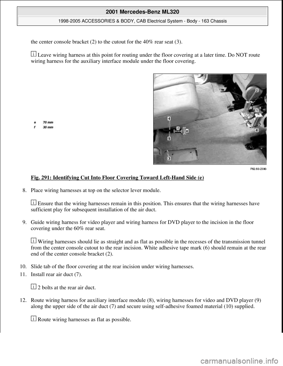
the center console bracket (2) to the cutout for the 40% rear seat (3).
Leave wiring harness at this point for routing under the floor covering at a later time. Do NOT route
wiring harness for the auxiliary interface module under the floor covering.
Fig. 291: Identifying Cut Into Floor Covering Toward Left
-Hand Side (e)
8. Place wiring harnesses at top on the selector lever module.
Ensure that the wiring harnesses remain in this position. This ensures that the wiring harnesses have
sufficient play for subsequent installation of the air duct.
9. Guide wiring harness for video player and wiring harness for DVD player to the incision in the floor
covering under the 60% rear seat.
Wiring harnesses should lie as straight and as flat as possible in the recesses of the transmission tunnel
from the center console cutout to the rear incision. White adhesive tape mark (6) should remain at the rear
end of the center console bracket (2).
10. Slide tab of the floor covering at the rear incision under wiring harnesses.
11. Install rear air duct (7).
2 bolts at the rear air duct.
12. Route wiring harness for auxiliary interface module (8), wiring harnesses for video and DVD player (9)
along the upper side of the air duct (7) and secure using self-adhesive foamed material (10) supplied.
Route wirin
g harnesses as flat as possible.
2001 Mercedes-Benz ML320
1998-2005 ACCESSORIES & BODY, CAB Electrical System - Body - 163 Chassis
me
Saturday, October 02, 2010 3:30:12 PMPage 377 © 2006 Mitchell Repair Information Company, LLC.
Page 1876 of 4133
Fig. 296: Identifying Rear Blower Motor And DVD Player Wiring Harness
6. Route wiring harness for additional interface module (4), wiring harness video player (2) and wiring
harness DVD player (3) together along the rear air duct (5).
7. Route wiring harness for additional interface module (4) on top side of left-hand junction of rear air duct.
8. Route wiring harness video player (2) and wiring harness DVD player (3) on top side of right-hand
junction of rear air duct.
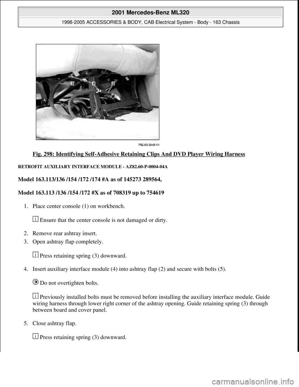
9. Fasten wiring harness to top side of rear air duct (5) with attached, self-adhesive foamed material (6).
10. Fasten video player and DVD player wiring harness to outside of bracket on center console (7) using
attached self-adhesive foamed material (6).
2001 Mercedes-Benz ML320
1998-2005 ACCESSORIES & BODY, CAB Electrical System - Body - 163 Chassis
me
Saturday, October 02, 2010 3:30:12 PMPage 381 © 2006 Mitchell Repair Information Company, LLC.
Page 1878 of 4133

Fig. 298: Identifying Self-Adhesive Retaining Clips And DVD Player Wiring Harness
RETROFIT AUXILIARY INTERFACE MODULE - AZ82.60-P-0004-04A
Model 163.113/136 /154 /172 /174 #A as of 145273 289564,
Model 163.113 /136 /154 /172 #X as of 708319 up to 754619
1. Place center console (1) on workbench.
Ensure that the center console is not damaged or dirty.
2. Remove rear ashtray insert.
3. Open ashtray flap completely.
Press retaining spring (3) downward.
4. Insert auxiliary interface module (4) into ashtray flap (2) and secure with bolts (5).
Do not overtighten bolts.
Previously installed bolts must be removed before installing the auxiliary interface module. Guide
wiring harness through lower right corner of the ashtray opening. Guide retaining spring (3) through
between board and cover panel.
5. Close ashtray flap.
Press retainin
g spring (3) downward.
2001 Mercedes-Benz ML320
1998-2005 ACCESSORIES & BODY, CAB Electrical System - Body - 163 Chassis
me
Saturday, October 02, 2010 3:30:12 PMPage 383 © 2006 Mitchell Repair Information Company, LLC.