Page 1879 of 4133
Fig. 299: Identifying Center Console, Auxiliary Interface Module And Retaining Spring
RETROFIT VIDEO PLAYER - AZ82.60-P-0004-05A
Model 163.136 /154 /172 #A as of 145273, Models 163.136 /154 /172 #X as of 708319, Models
163.113/128 /157 /174 /175
Rear seats
1. Unscrew rear nut (1) and bolt (2) from 60% rear seat.
2. Position bracket (3)and secure with bolt (2) and nut (1) .
Insert bolt with Loctite. Replace nut.
3. Install covers under the 60% rear bench.
Replace center cover at rear seat bench at bottom with cover from the conversion kit. Do NOT install
shade at front at the 60% bench.
NumberDesignationModel 163 as of 09/99
BA91.12-P-1005-03ANuts for rear seat console
on vehicle floorNM40
BA91.12-P-1008-03AScrews for rear seat
console on vehicle floorNM40
2001 Mercedes-Benz ML320
1998-2005 ACCESSORIES & BODY, CAB Electrical System - Body - 163 Chassis
me
Saturday, October 02, 2010 3:30:12 PMPage 384 © 2006 Mitchell Repair Information Company, LLC.
Page 1885 of 4133
Fig. 307: Identifying Wiring Harness Fo r Auxiliary Interface Module And Clip
Fig. 308: Identifying Auxiliary Interface Module Connector And Mount For Center Console
Remove
1Remove center console
Remove/install center
console AR68.20-P-2000GH
2Remove center console
insulating mat
3Remove rear air duct Up to VIN A289564,
X754619. 2 screws at
rear air duct.
4Remove radio (A2)
Remove/install radio AR82.60-P-7502EA
5Remove glove
compartment
2001 Mercedes-Benz ML320
1998-2005 ACCESSORIES & BODY, CAB Electr ical System - Body - 163 Chassis
me
Saturday, October 02, 2010 3:30:12 PMPage 390 © 2006 Mitchell Repair Information Company, LLC.
Page 1887 of 4133

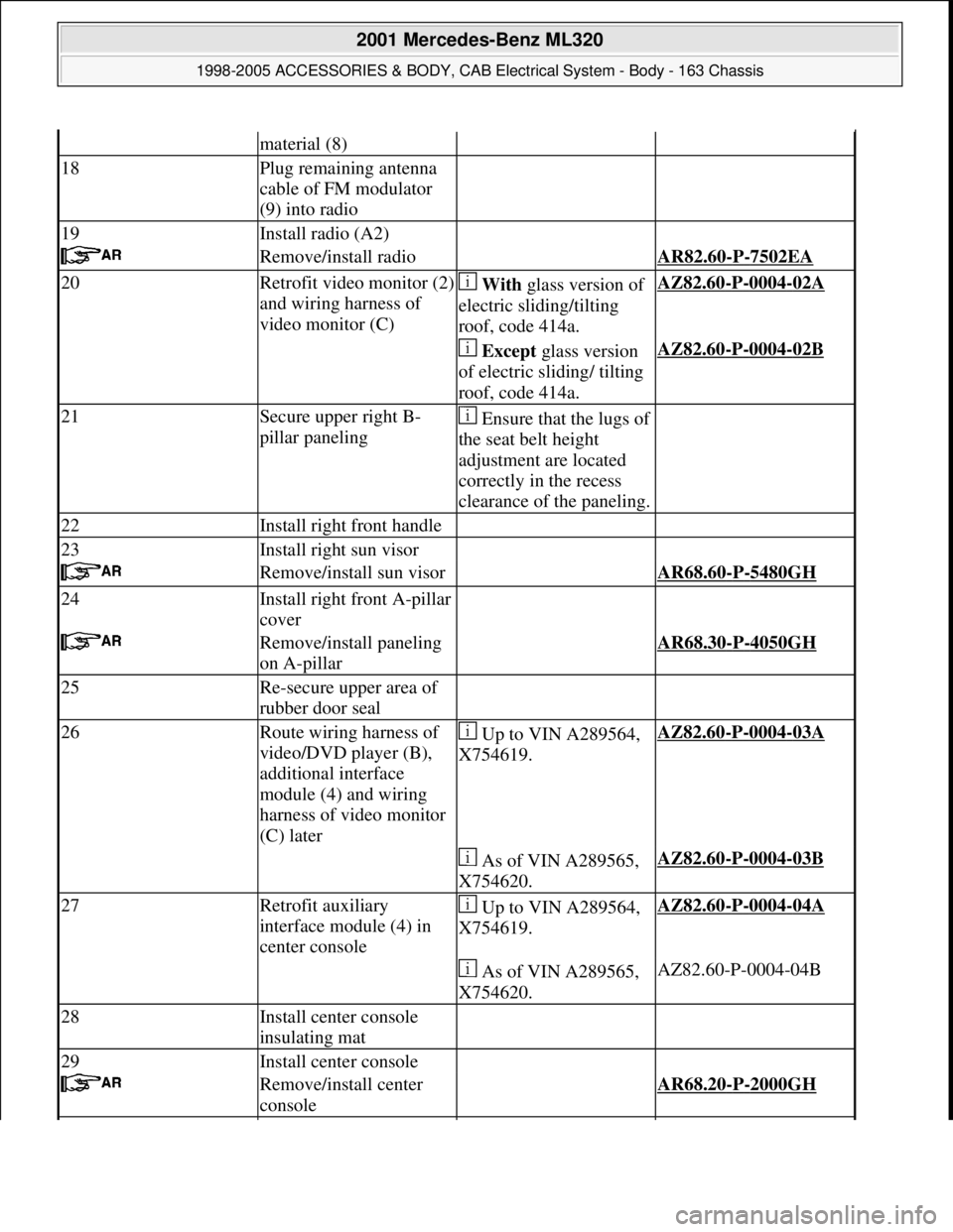
material (8)
18Plug remaining antenna
cable of FM modulator
(9) into radio
19Install radio (A2)
Remove/install radio AR82.60-P-7502EA
20Retrofit video monitor (2)
and wiring harness of
video monitor (C) With glass version of
electric sliding/tilting
roof, code 414a.AZ82.60-P-0004-02A
Except glass version
of electric sliding/ tilting
roof, code 414a.AZ82.60-P-0004-02B
21Secure upper right B-
pillar paneling Ensure that the lugs of
the seat belt height
adjustment are located
correctly in the recess
clearance of the paneling.
22Install right front handle
23Install right sun visor
Remove/install sun visor AR68.60-P-5480GH
24Install right front A-pillar
cover
Remove/install paneling
on A-pillar AR68.30-P-4050GH
25Re-secure upper area of
rubber door seal
26Route wiring harness of
video/DVD player (B),
additional interface
module (4) and wiring
harness of video monitor
(C) later Up to VIN A289564,
X754619.AZ82.60-P-0004-03A
As of VIN A289565,
X754620.AZ82.60-P-0004-03B
27Retrofit auxiliary
interface module (4) in
center console Up to VIN A289564,
X754619.AZ82.60-P-0004-04A
As of VIN A289565,
X754620.AZ82.60-P-0004-04B
28Install center console
insulating mat
29Install center console
Remove/install center
console AR68.20-P-2000GH
2001 Mercedes-Benz ML320
1998-2005 ACCESSORIES & BODY, CAB Electrical System - Body - 163 Chassis
me
Saturday, October 02, 2010 3:30:12 PMPage 392 © 2006 Mitchell Repair Information Company, LLC.
Page 1888 of 4133

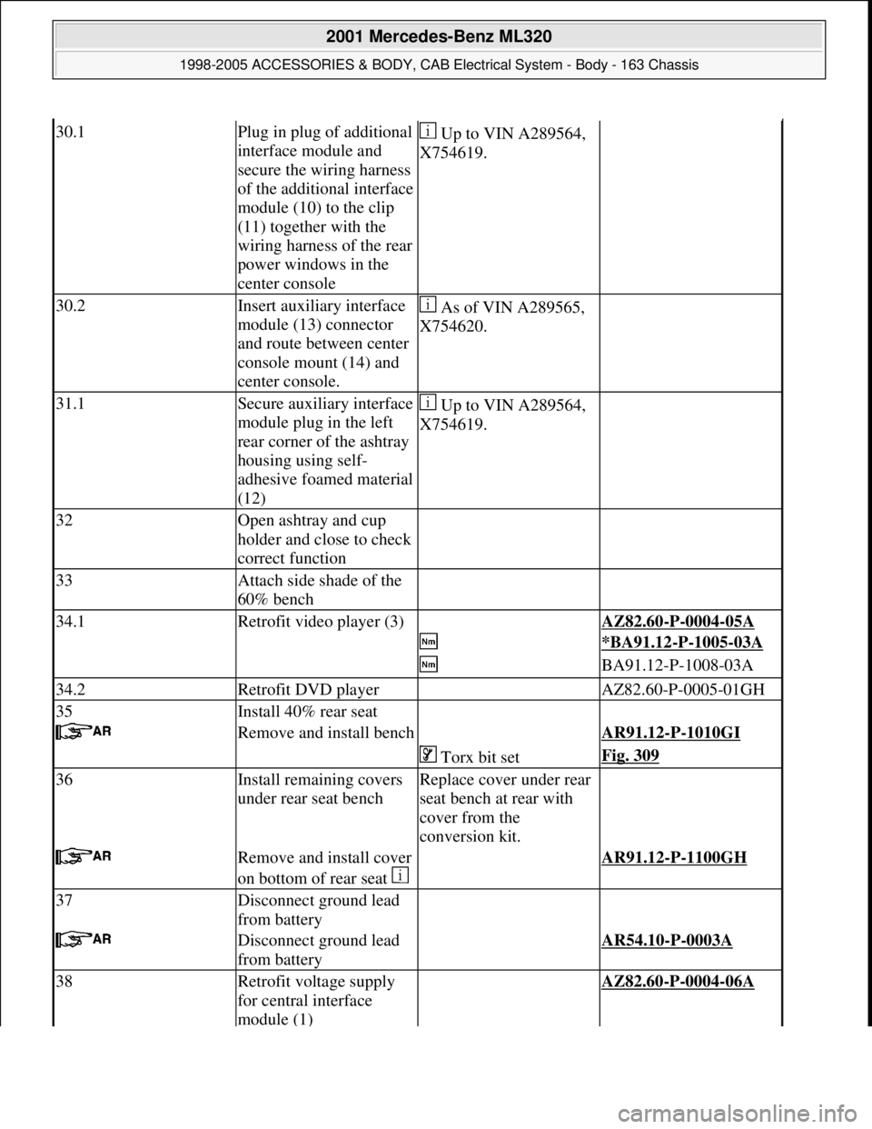
30.1Plug in plug of additional
interface module and
secure the wiring harness
of the additional interface
module (10) to the clip
(11) together with the
wiring harness of the rear
power windows in the
center console Up to VIN A289564,
X754619.
30.2Insert auxiliary interface
module (13) connector
and route between center
console mount (14) and
center console. As of VIN A289565,
X754620.
31.1Secure auxiliary interface
module plug in the left
rear corner of the ashtray
housing using self-
adhesive foamed material
(12) Up to VIN A289564,
X754619.
32Open ashtray and cup
holder and close to check
correct function
33Attach side shade of the
60% bench
34.1Retrofit video player (3) AZ82.60-P-0004-05A
*BA91.12-P-1005-03A
BA91.12-P-1008-03A
34.2Retrofit DVD player AZ82.60-P-0005-01GH
35Install 40% rear seat
Remove and install bench AR91.12-P-1010GI
Torx bit setFig. 309
36Install remaining covers
under rear seat benchReplace cover under rear
seat bench at rear with
cover from the
conversion kit.
Remove and install cover
on bottom of rear seat AR91.12-P-1100GH
37Disconnect ground lead
from battery
Disconnect ground lead
from battery AR54.10-P-0003A
38Retrofit voltage supply
for central interface
module (1) AZ82.60-P-0004-06A
2001 Mercedes-Benz ML320
1998-2005 ACCESSORIES & BODY, CAB Electrical System - Body - 163 Chassis
me
Saturday, October 02, 2010 3:30:12 PMPage 393 © 2006 Mitchell Repair Information Company, LLC.
Page 1892 of 4133
Fig. 312: Identifying Trafficstar Wiring Harness With Sound
1. Position CAN bus adapter (5) in center of center console strut and mark holes (b).
2. Drill holes (b) with 6.2 mm dia. bit.
Fig. 313: Identifying Mark Holes
3. Fasten CAN bus adapter (5) to center console strut with two self-tapping screws (a) from parts kit.
Screw screws through strut from below into CAN bus adapter mount.
Fig. 314: Identifying CAN Bus Adapter And Self
-Tapping Screws
4. Disconnect standard wiring harness (2) from transfer case control module (N78).
5. Connect CAN bus (9) standard wiring harness between transfer case control module (N78) and standard
wiring harness (2).
6. Route CAN bus (6) lead on fan duct.
2001 Mercedes-Benz ML320
1998-2005 ACCESSORIES & BODY, CAB Electrical System - Body - 163 Chassis
me
Saturday, October 02, 2010 3:30:12 PMPage 397 © 2006 Mitchell Repair Information Company, LLC.
Page 1893 of 4133
Fig. 315: Identifying Transfer Case Cont rol Module And CAN Bus Wiring Harness
7. Route connector (8) for TrafficStar wiring harness (4) from radio shaft along fan duct to center console.
Fig. 316: Identifying Trafficstar Wiring Harness And Connector
Steps 8-11 apply only for vehicl es with manual transmission
8. Separate green lead (gn) from CAN bus ad apter connector (8) (see magnifying glass).
9. Tie TrafficStar (4) wiring harn ess on at height of shift gate and pull out green lead (gn).
Fig. 317: Identifying CAN Bus Adapter Conn ector And Trafficstar Wiring Harness
10. Route green lead (gn) to bac
k-up lamp switch (S16/2).
2001 Mercedes-Benz ML320
1998-2005 ACCESSORIES & BODY, CAB Electr ical System - Body - 163 Chassis
me
Saturday, October 02, 2010 3:30:12 PMPage 398 © 2006 Mitchell Repair Information Company, LLC.
Page 1894 of 4133
11. Connect lower gray lead (gr) from connector with assignment 2 for back-up lamp switch (S16/2) to green
lead (gn) using solder connector.
The connector for the back-up lamp switch (S16/2) has two gray leads, the lower of the two leads is for
the switched back-up lamp signal.
Fig. 318: Identifying Back
-Up Lamp Switch And Green Lead
12. Connect connector (8) and lead (6) to CAN bus adapter (5).
13. Install center console.
Fig. 319: Identifying CAN Bus Adapter And Lead
14. Connect brown and black wire (br, sw) from GPS ante nna lead (3) with brown and black lead (br, sw)
from TrafficStar wiring harness (4) and slide flat plug insulations together.
15. Attach flat plu
g connectors and GPS antenna le ad (3) to TrafficStar wiring harness (4) with felt.
2001 Mercedes-Benz ML320
1998-2005 ACCESSORIES & BODY, CAB Electr ical System - Body - 163 Chassis
me
Saturday, October 02, 2010 3:30:12 PMPage 399 © 2006 Mitchell Repair Information Company, LLC.
Page 1897 of 4133
Fig. 324: Identifying Trafficsta r Wiring Harness With Sound
1. Position CAN bus adapter (5) in center of center console strut and mark holes (b).
2. Drill holes (b) with 6.2 mm dia. bit.
Fig. 325: Identifying Mark Holes
3. Fasten CAN bus adapter (5) to center console strut with two self-tapping screws (a) from parts kit.
Screw screws throu
gh strut from below into CAN bus adapter mount.
2001 Mercedes-Benz ML320
1998-2005 ACCESSORIES & BODY, CAB Electr ical System - Body - 163 Chassis
me
Saturday, October 02, 2010 3:30:12 PMPage 402 © 2006 Mitchell Repair Information Company, LLC.