Page 2152 of 4133

COMPONENT LOCATION GRAPHICS
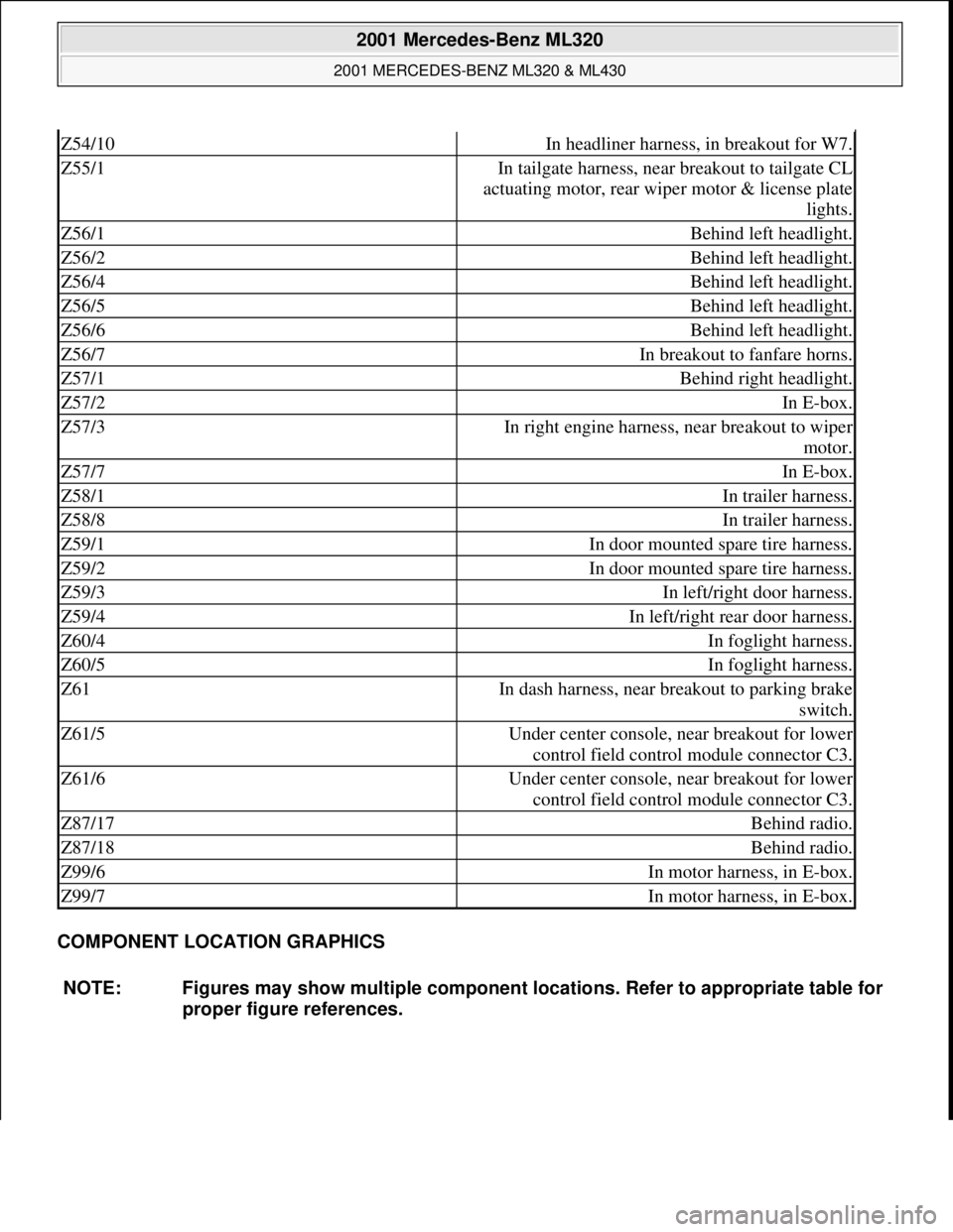
Z54/10In headliner harness, in breakout for W7.
Z55/1In tailgate harness, near breakout to tailgate CL
actuating motor, rear wiper motor & license plate
lights.
Z56/1Behind left headlight.
Z56/2Behind left headlight.
Z56/4Behind left headlight.
Z56/5Behind left headlight.
Z56/6Behind left headlight.
Z56/7In breakout to fanfare horns.
Z57/1Behind right headlight.
Z57/2In E-box.
Z57/3In right engine harness, near breakout to wiper
motor.
Z57/7In E-box.
Z58/1In trailer harness.
Z58/8In trailer harness.
Z59/1In door mounted spare tire harness.
Z59/2In door mounted spare tire harness.
Z59/3In left/right door harness.
Z59/4In left/right rear door harness.
Z60/4In foglight harness.
Z60/5In foglight harness.
Z61In dash harness, near breakout to parking brake
switch.
Z61/5Under center console, near breakout for lower
control field control module connector C3.
Z61/6Under center console, near breakout for lower
control field control module connector C3.
Z87/17Behind radio.
Z87/18Behind radio.
Z99/6In motor harness, in E-box.
Z99/7In motor harness, in E-box.
NOTE: Figures may show multiple component locations. Refer to appropriate table for
proper figure references.
2001 Mercedes-Benz ML320
2001 MERCEDES-BENZ ML320 & ML430
me
Saturday, October 02, 2010 3:21:17 PMPage 12 © 2006 Mitchell Repair Information Company, LLC.
Page 3254 of 4133
Fig. 3: Identifying Air Inlet
AIR DUCT LOCATIONS - GF83.10-P-2101-01GH
The lateral nozzle and side window defroster nozzle (3) air ducts are on the left and right below the instrument
panel.
The windshield defroster nozzle air duct (2) is on top of the heater/evaporator housing (front center) below the
instrument panel.
The center nozzle air duct (1) is on top of the heater box/evaporator housing behind the center nozzle.
The front footwell air duct (4) is integrated in the heater/evaporator housing.
The rear footwell air duct (5) is below the center console.
2001 Mercedes-Benz ML320
1998-2005 HVAC Climate Control - 163 Chassis
me
Saturday, October 02, 2010 3:23:14 PMPage 10 © 2006 Mitchell Repair Information Company, LLC.
Page 3255 of 4133
Fig. 4: Identifying Air Duct (Up To 31.08.01)
AIR DUCT LOCATIONS - GF83.10-P-2101-01GI
The lateral nozzle and side window defroster nozzle (3) air ducts are on the left and right below the instrument
panel.
The windshield defroster nozzle air duct (2) is on top of the evaporator housing (front center) below the
instrument panel.
The center nozzle air duct (1) is on top of the evaporator housing behind the center nozzle.
The front footwell air duct (4) is integrated in the heater/evaporator housing.
The rear compartment air duct (5) is located below the center console.
The rear footwell air duct (6) is at the bottom next to the rear blower behind the center console.
2001 Mercedes-Benz ML320
1998-2005 HVAC Climate Control - 163 Chassis
me
Saturday, October 02, 2010 3:23:14 PMPage 11 © 2006 Mitchell Repair Information Company, LLC.
Page 3261 of 4133
CENTER NOZZLE, LOCA TION - GF83.10-P-2107-02GH
The center nozzle (1) is located above the center console in the instrument panel.
Fig. 12: Identifying Center Nozzle
SIDE NOZZLE, FUNCTI ON - GF83.10-P-2108-01GH
Function
The side nozzle (3) can be adjusted infinitely or opened and closed completely with the dial.
The air exit direction can be adjusted upward, downward, to the left, to the right or middle as desired with the
louver system.
Heated/cooled air exits th rough the side nozzle (3).
Fig. 13: Identifying Side Nozzle
SIDE NOZZLE, LOCATI ON - GF83.10-P-2108-02GH
2001 Mercedes-Benz ML320
1998-2005 HVAC Climate Control - 163 Chassis
me
Saturday, October 02, 2010 3:23:14 PMPage 17 © 2006 Mitchell Repair Information Company, LLC.
Page 3275 of 4133
Fig. 25: Identifying Rear Nozzle
SERIES RESISTOR GROUP, LOCATION/TASK/FUNCTION - GF83.10-P-2161GC
MODEL 163 up to 31.8.01, 168
Rear nozzle
positionThe rear nozzle (1) is located at the rear center console.
Rear nozzle
taskThe rear compartment nozzle provides specific rear compartment
ventilation in addition to the rear footwell air vents.
Rear nozzle
function GF83.10-P-
2111-01GI
Series resistor group,
positionModel 168GF83.10-P-2124-
01GC
Model 163GF83.10-P-2124-
01GH
Series resistor
assembly taskThe series resistor assembly controls the blower voltage
depending on the relevant blower level setting.
Series resistor
assembly functionModel 168 up to 28.02.01GF83.10-P-2124-
02GC
Model 168 as of 01.03.01GF83.10-P-2124-
02GH
Model 163GF83.10-P-2124-
2001 Mercedes-Benz ML320
1998-2005 HVAC Climate Control - 163 Chassis
me
Saturday, October 02, 2010 3:23:15 PMPage 31 © 2006 Mitchell Repair Information Company, LLC.
Page 3276 of 4133

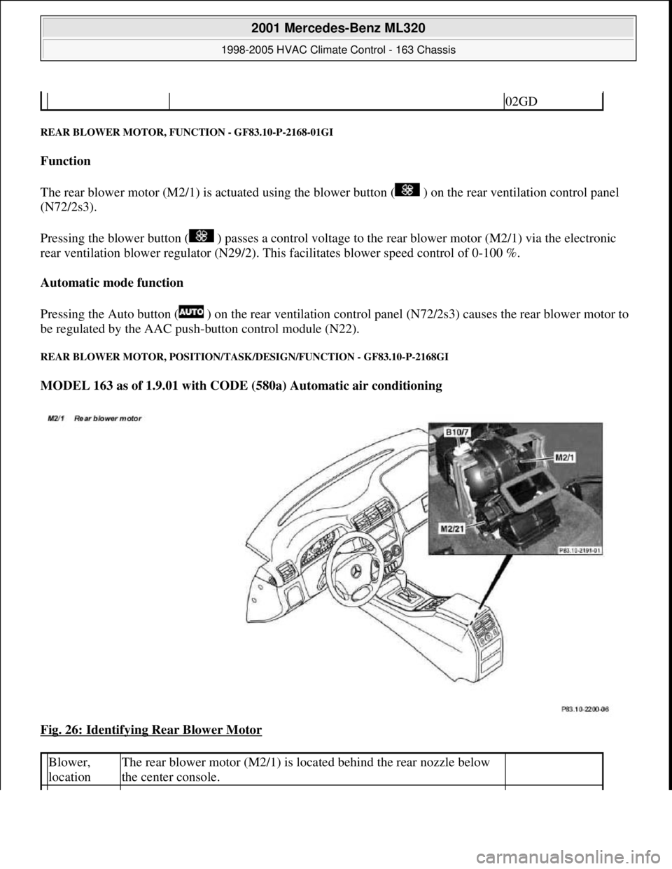
REAR BLOWER MOTOR, FU NCTION - GF83.10-P-2168-01GI
Function
The rear blower motor (M2/1) is actuated using the bl ower button ( ) on the rear ventilation control panel
(N72/2s3).
Pressing the blower button ( ) passes a control voltage to the rear blower motor (M2/1) via the electronic
rear ventilation blower regulat or (N29/2). This facilitates blower speed control of 0-100 %.
Automatic mode function
Pressing the Auto button ( ) on the rear ventilation control panel (N72/2s3) causes the rear blower motor to
be regulated by the AAC push- button control module (N22).
REAR BLOWER MOTOR, PO SITION/TASK/DESIGN/FUNCTION - GF83.10-P-2168GI
MODEL 163 as of 1.9.01 with CODE (580a) Automatic air conditioning
Fig. 26: Identifying Rear Blower Motor
02GD
Blower,
locationThe rear blower motor (M2/1) is located behind the rear nozzle below
the center console.
2001 Mercedes-Benz ML320
1998-2005 HVAC Climate Control - 163 Chassis
me
Saturday, October 02, 2010 3:23:15 PMPage 32 © 2006 Mitchell Repair Information Company, LLC.
Page 3285 of 4133

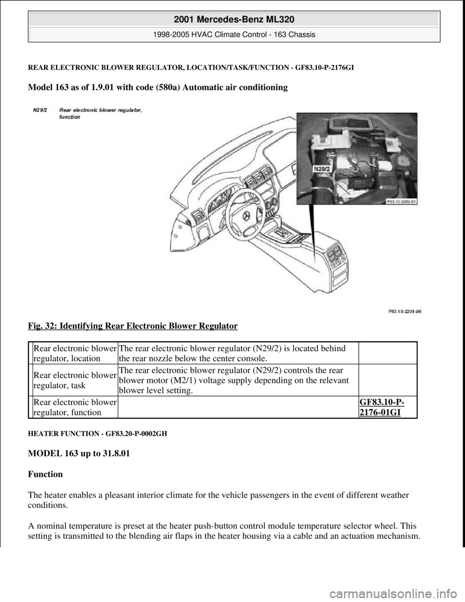
REAR ELECTRONIC BLOWER REGULATOR, LOCATION/TASK/FUNCTION - GF83.10-P-2176GI
Model 163 as of 1.9.01 with code (580a) Automatic air conditioning
Fig. 32: Identifying Rear Electronic Blower Regulator
HEATER FUNCTION - GF83.20-P-0002GH
MODEL 163 up to 31.8.01
Function
The heater enables a pleasant interior climate for the vehicle passengers in the event of different weather
conditions.
A nominal temperature is preset at the heater push-button control module temperature selector wheel. This
setting is transmitted to the blending air flaps in the heater housing via a cable and an actuation mechanism.
Rear electronic blower
regulator, locationThe rear electronic blower regulator (N29/2) is located behind
the rear nozzle below the center console.
Rear electronic blower
regulator, taskThe rear electronic blower regulator (N29/2) controls the rear
blower motor (M2/1) voltage supply depending on the relevant
blower level setting.
Rear electronic blower
regulator, function GF83.10-P-
2176-01GI
2001 Mercedes-Benz ML320
1998-2005 HVAC Climate Control - 163 Chassis
me
Saturday, October 02, 2010 3:23:15 PMPage 41 © 2006 Mitchell Repair Information Company, LLC.
Page 3310 of 4133
Fig. 56: Identifying Blower Switch, Temperature Selector Wheel And Air Distribution Switch
AIR CONDITIONING CONTROL MODULE, LOCATION - GF83.30-P-2102-02GH
The AC control module (N19) is located behind the center console to the left of the evaporator housing.
Fig. 57: Identifying AC Control Module
Blower switch, location/task/design/function GF83.25-P-2100GC
Air distribution switch, location/task/design/ function GF83.25-P-2101GH
Temperature selector wheel, location/task/ design/function GF83.25-P-2102GC
Air recirculation switch, location/task/design/ function GF83.10-P-2117GH
AC button, location/task/function GF83.30-P-2103GH
AC control module location/task/function GF83.30-P-2102GH
All-activity module, location/task/function GF54.21-P-4110GH
2001 Mercedes-Benz ML320
1998-2005 HVAC Climate Control - 163 Chassis
me
Saturday, October 02, 2010 3:23:15 PMPage 66 © 2006 Mitchell Repair Information Company, LLC.