1997 MERCEDES-BENZ ML350 height
[x] Cancel search: heightPage 2501 of 4133
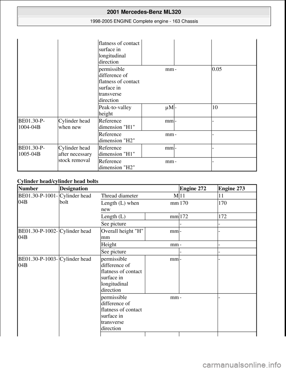
Cylinder head/cyl inder head bolts
flatness of contact
surface in
longitudinal
direction
permissible
difference of
flatness of contact
surface in
transverse
directionmm-0.05
Peak-to-valley
heightµM-10
BE01.30-P-
1004-04BCylinder head
when newReference
dimension "H1"mm--
Reference
dimension "H2"mm--
BE01.30-P-
1005-04BCylinder head
after necessary
stock removalReference
dimension "H1"mm--
Reference
dimension "H2"mm--
NumberDesignationEngine 272Engine 273
BE01.30-P-1001-
04BCylinder head
boltThread diameterM1111
Length (L) when
newmm170170
Length (L)mm172172
See picture--
BE01.30-P-1002-
04BCylinder headOverall height "H"
mmmm--
Heightmm--
See picture--
BE01.30-P-1003-
04BCylinder headpermissible
difference of
flatness of contact
surface in
longitudinal
directionmm--
permissible
difference of
flatness of contact
surface in
transverse
directionmm--
2001 Mercedes-Benz ML320
1998-2005 ENGINE Complete engine - 163 Chassis
me
Saturday, October 02, 2010 3:17:58 PMPage 145 © 2006 Mitchell Repair Information Company, LLC.
Page 2502 of 4133
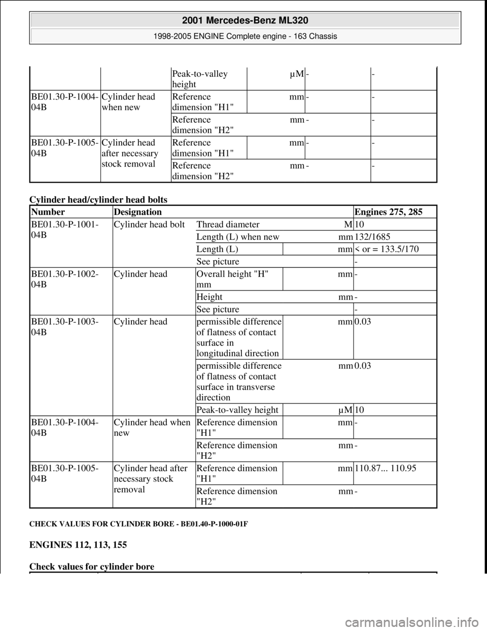
Cylinder head/cyl inder head bolts
CHECK VALUES FOR CYLINDER BORE - BE01.40-P-1000-01F
ENGINES 112, 113, 155
Check values for cylinder bore
Peak-to-valley
heightµM--
BE01.30-P-1004-
04BCylinder head
when newReference
dimension "H1"mm--
Reference
dimension "H2"mm--
BE01.30-P-1005-
04BCylinder head
after necessary
stock removalReference
dimension "H1"mm--
Reference
dimension "H2"mm--
NumberDesignationEngines 275, 285
BE01.30-P-1001-
04BCylinder head boltThread diameterM10
Length (L) when newmm132/1685
Length (L)mm< or = 133.5/170
See picture-
BE01.30-P-1002-
04BCylinder headOverall height "H"
mmmm-
Heightmm-
See picture-
BE01.30-P-1003-
04BCylinder headpermissible difference
of flatness of contact
surface in
longitudinal directionmm0.03
permissible difference
of flatness of contact
surface in transverse
directionmm0.03
Peak-to-valley heightµM10
BE01.30-P-1004-
04BCylinder head when
newReference dimension
"H1"mm-
Reference dimension
"H2"mm-
BE01.30-P-1005-
04BCylinder head after
necessary stock
removalReference dimension
"H1"mm110.87... 110.95
Reference dimension
"H2"mm-
2001 Mercedes-Benz ML320
1998-2005 ENGINE Complete engine - 163 Chassis
me
Saturday, October 02, 2010 3:17:58 PMPage 146 © 2006 Mitchell Repair Information Company, LLC.
Page 2514 of 4133
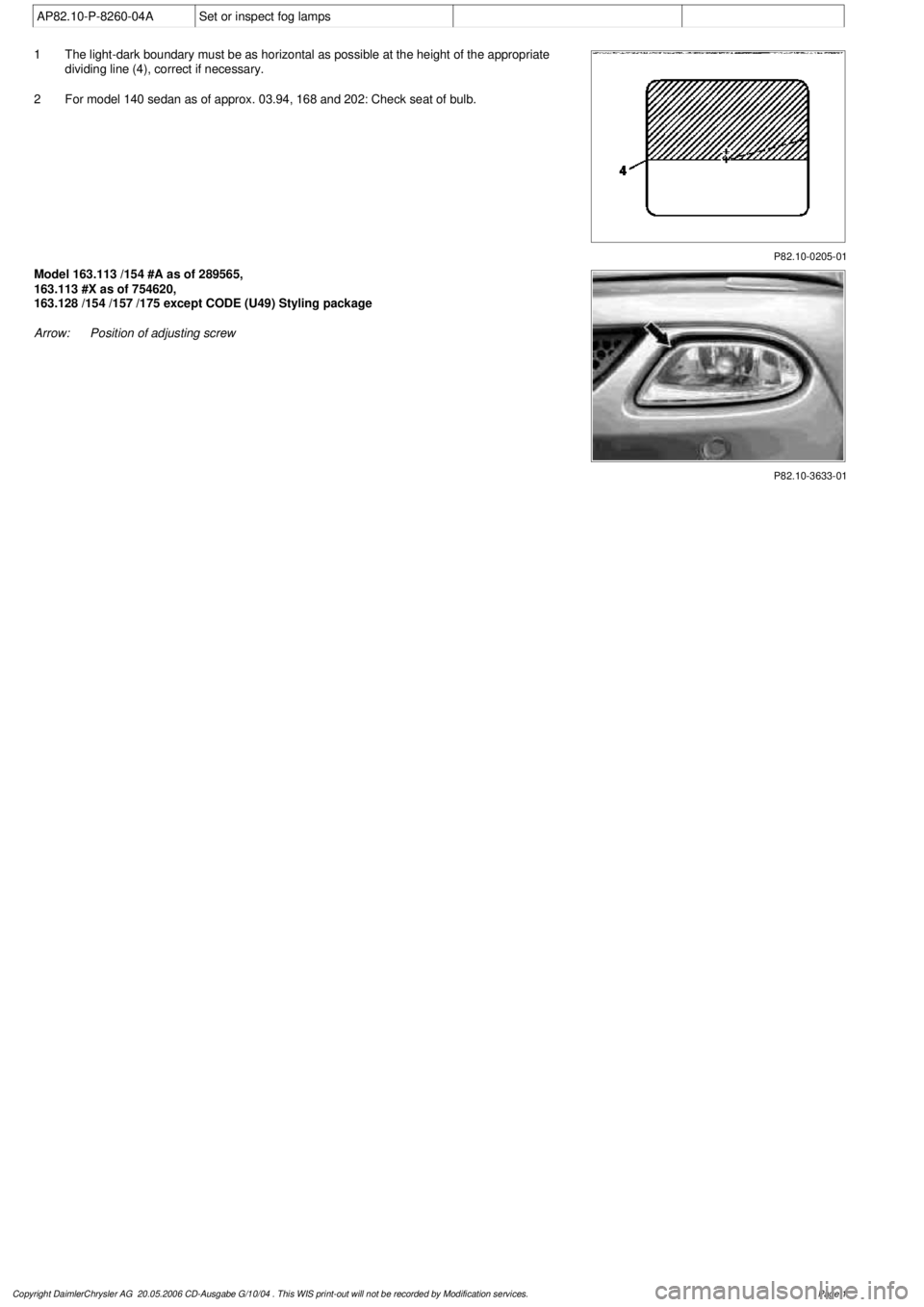
AP82.10-P-8260-04A
Set or inspect fog lamps
P82.10-0205-01
1
The light-dark boundary must be as horizontal as possible at the height of the appropriate
dividing line (4), correct if necessary.
2
For model 140 sedan as of approx. 03.94, 168 and 202: Check seat of bulb.
P82.10-3633-01
Model 163.113 /154 #A as of 289565,
163.113 #X as of 754620,
163.128 /154 /157 /175 except CODE (U49) Styling package
Arrow:
Position of adjusting screw
Copyright DaimlerChrysler AG 20.05.2006 CD-Ausgabe G/10/04 . This WIS print-out will not be recorde
d by Modification services.
Page 1
Page 2658 of 4133
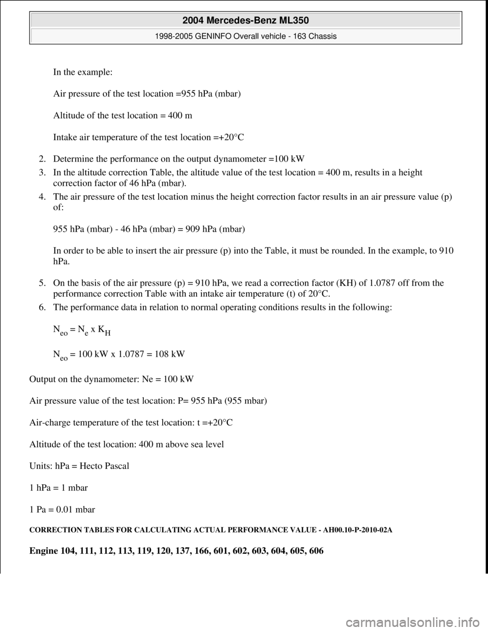
In the example:
Air pressure of the test location =955 hPa (mbar)
Altitude of the test location = 400 m
Intake air temperature of the test location =+20°C
2. Determine the performance on the output dynamometer =100 kW
3. In the altitude correction Table, the altitude value of the test location = 400 m, results in a height
correction factor of 46 hPa (mbar).
4. The air pressure of the test location minus the height correction factor results in an air pressure value (p)
of:
955 hPa (mbar) - 46 hPa (mbar) = 909 hPa (mbar)
In order to be able to insert the air pressure (p) into the Table, it must be rounded. In the example, to 910
hPa.
5. On the basis of the air pressure (p) = 910 hPa, we read a correction factor (KH) of 1.0787 off from the
performance correction Table with an intake air temperature (t) of 20°C.
6. The performance data in relation to normal operating conditions results in the following:
N
eo = Ne x KH
N
eo = 100 kW x 1.0787 = 108 kW
Output on the dynamometer: Ne = 100 kW
Air pressure value of the test location: P= 955 hPa (955 mbar)
Air-charge temperature of the test location: t =+20°C
Altitude of the test location: 400 m above sea level
Units: hPa = Hecto Pascal
1 hPa = 1 mbar
1 Pa = 0.01 mbar
CORRECTION TABLES FOR CALCULATING ACTUAL PERFORMANCE VALUE - AH00.10-P-2010-02A
Engine 104, 111, 112, 113, 119, 120, 137, 166, 601, 602, 603, 604, 605, 606
2004 Mercedes-Benz ML350
1998-2005 GENINFO Overall vehicle - 163 Chassis
me
Saturday, October 02, 2010 3:47:44 PMPage 13 © 2006 Mitchell Repair Information Company, LLC.
Page 2868 of 4133
Align vehicle between the columns of the lifting platform and position the four support plates at the
lifting platform support points specified by the vehicle manufacturer.
RISK OF ACCIDENT AND INJURY
Please make sure that:
The vehicle is centered lengthwise and crosswise between the lifting platform columns.
The support plates on the lifting platform support points are all positioned at the same height.
The vehicle is first raised a few inches (wheels are still touching the ground) and the position and fit of
the support plates and lift points are checked before raising the vehicle to the full lifted position.
The vehicle is not raised off the lifting platform plates when components are being supported.
If the arms of the lifting platform or the support plates are not positioned properly, or if components of the
vehicle are supported so that the vehicle raises off the platform, then the vehicle can slip off the platform and
cause life-threatening injuries to you or other people.
Before removing axles and assemblies from the vehicle, make sure the vehicle is secured to the platform or that
sand bags are used to balance the vehicle out.
Otherwise the vehicle could tip because of the uneven distribution of weight. This could cause life-threatening
injuries to you or other people.
RISK OF INJURY CAUSED BY FINGERS BEING JAMMED OR PINCHED WHEN REMOVING, INSTALLING OR
ALIGNING HOODS, DOORS, TRUNK LID/ REAR-END DOOR OR SLIDING ROOF. - AS00.00-Z-0011-01A
When moving components, ensure that no body parts or limbs are within the operating range of moving
parts.
Risk of injury
When working on hoods, doors, trunk lids/tailgates and sliding roofs and on their connecting mechanisms,
serious injuries can occur due to cutting, jamming or pinching of body parts like fingers and hands.
Safety instructions/precautions
Be careful when working in hazardous areas.
When moving components, secure the movement area of the mechanism to prevent interference.
Use special tool or other means to ensure safe distance to dangerous areas. NOTE: In Germany, lift platform operators must observe the following regulations and
guidelines: "Berufsgenossenschaftvorschrift (BGV) D29 fur Hebebuhnen" and
the guidelines issued by the lift platform manufacturer. In other countries,
operators must comply with all relevant statutory and accident prevention
regulations.
2004 Mercedes-Benz ML350
1998-2005 GENINFO Overall vehicle - 163 Chassis
me
Saturday, October 02, 2010 3:47:47 PMPage 223 © 2006 Mitchell Repair Information Company, LLC.
Page 3186 of 4133
AP82.10-P-8260GH
Check and correct headlamp adjustment
2.7.97
MODEL
163
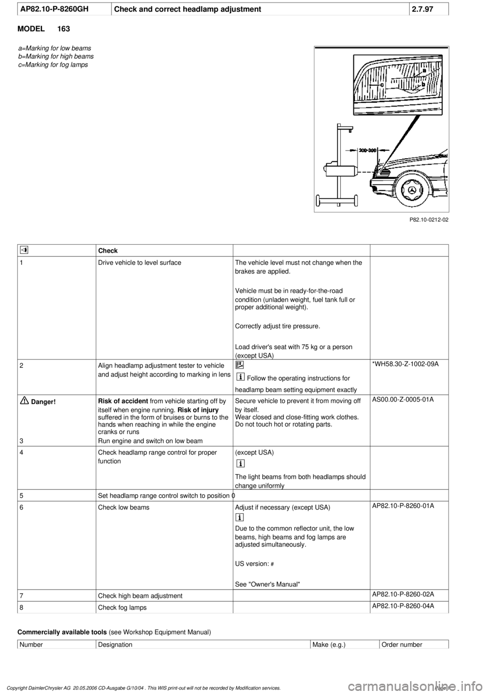
a=Marking for low beams
b=Marking for high beams
c=Marking for fog lamps
P82.10-0212-02
Check
1
Drive vehicle to level surface
The vehicle level must not change when the
brakes are applied.
Vehicle must be in ready-for-the-road
condition (unladen weight, fuel tank full or
proper additional weight).
Correctly adjust tire pressure.
Load driver's seat with 75 kg or a person
(except USA)
2
Align headlamp adjustment tester to vehicle
and adjust height according to marking in lens
Follow the operating instructions for
headlamp beam setting equipment exactly
*WH58.30-Z-1002-09A
Danger!
Risk of accident
from vehicle starting off by
itself when engine running.
Risk of injury
suffered in the form of bruises or burns to the
hands when reaching in while the engine
cranks or runs
Secure vehicle to prevent it from moving off
by itself.
Wear closed and close-fitting work clothes.
Do not touch hot or rotating parts.
AS00.00-Z-0005-01A
3
Run engine and switch on low beam
4
Check headlamp range control for proper
function
(except USA)
The light beams from both headlamps should
change uniformly
5
Set headlamp range control switch to position 0
6
Check low beams
Adjust if necessary (except USA)
AP82.10-P-8260-01A
Due to the common reflector unit, the low
beams, high beams and fog lamps are
adjusted simultaneously.
US version:
#
See "Owner's Manual"
7
Check high beam adjustment
AP82.10-P-8260-02A
8
Check fog lamps
AP82.10-P-8260-04A
Commercially available tools
(see Workshop Equipment Manual)
Number
Designation
Make (e.g.)
Order number
Copyright DaimlerChrysler AG 20.05.2006 CD-Ausgabe G/10/04 . This WIS print-out will not be recorde
d by Modification services.
Page 1
Page 3193 of 4133
AR88.40-P-3020GH
Adjust engine hood
8.4.99
MODEL
163.113 /128 /136 /154 /157 /172 /174 /175
P88.40-2067-09
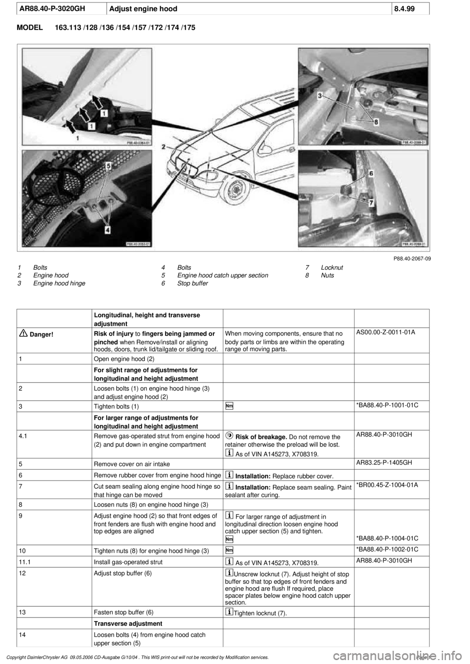
1
Bolts
2
Engine hood
3
Engine hood hinge
7
Locknut
8
Nuts
4
Bolts
5
Engine hood catch upper section
6
Stop buffer
Longitudinal, height and transverse
adjustment
Danger!
Risk of injury
to
fingers being jammed or
pinched
when Remove/install or aligning
hoods, doors, trunk lid/tailgate or sliding roof.
When moving components, ensure that no
body parts or limbs are within the operating
range of moving parts.
AS00.00-Z-0011-01A
1
Open engine hood (2)
For slight range of adjustments for
longitudinal and height adjustment
2
Loosen bolts (1) on engine hood hinge (3)
and adjust engine hood (2)
3
Tighten bolts (1)
*BA88.40-P-1001-01C
For larger range of adjustments for
longitudinal and height adjustment
4.1
Remove gas-operated strut from engine hood
(2) and put down in engine compartment
Risk of breakage. Do not remove the
retainer otherwise the preload will be lost.
AR88.40-P-3010GH
As of VIN A145273, X708319.
5
Remove cover on air intake
AR83.25-P-1405GH
6
Remove rubber cover from engine hood hinge
Installation:
Replace rubber cover.
7
Cut seam sealing along engine hood hinge so
that hinge can be moved
Installation:
Replace seam sealing. Paint
sealant after curing.
*BR00.45-Z-1004-01A
8
Loosen nuts (8) on engine hood hinge (3)
9
Adjust engine hood (2) so that front edges of
front fenders are flush with engine hood and
top edges are aligned
For larger range of adjustment in
longitudinal direction loosen engine hood
catch upper section (5) and tighten.
*BA88.40-P-1004-01C
10
Tighten nuts (8) for engine hood hinge (3)
*BA88.40-P-1002-01C
11.1
Install gas-operated strut
As of VIN A145273, X708319.
AR88.40-P-3010GH
12
Adjust stop buffer (6)
Unscrew locknut (7). Adjust height of stop
buffer so that top edges of front fenders and
engine hood are flush If required, place
spacer plates below engine hood catch upper
section.
13
Fasten stop buffer (6)
Tighten locknut (7).
Transverse adjustment
14
Loosen bolts (4) from engine hood catch
upper section (5)
Copyright DaimlerChrysler AG 09.05.2006 CD-Ausgabe G/10/04 . This WIS print-out will not be recorde
d by Modification services.
Page 1
Page 3195 of 4133
AR88.40-P-3020GH
Adjust engine hood
8.4.99
MODEL
163.113 /128 /136 /154 /157 /172 /174 /175
P88.40-2067-09
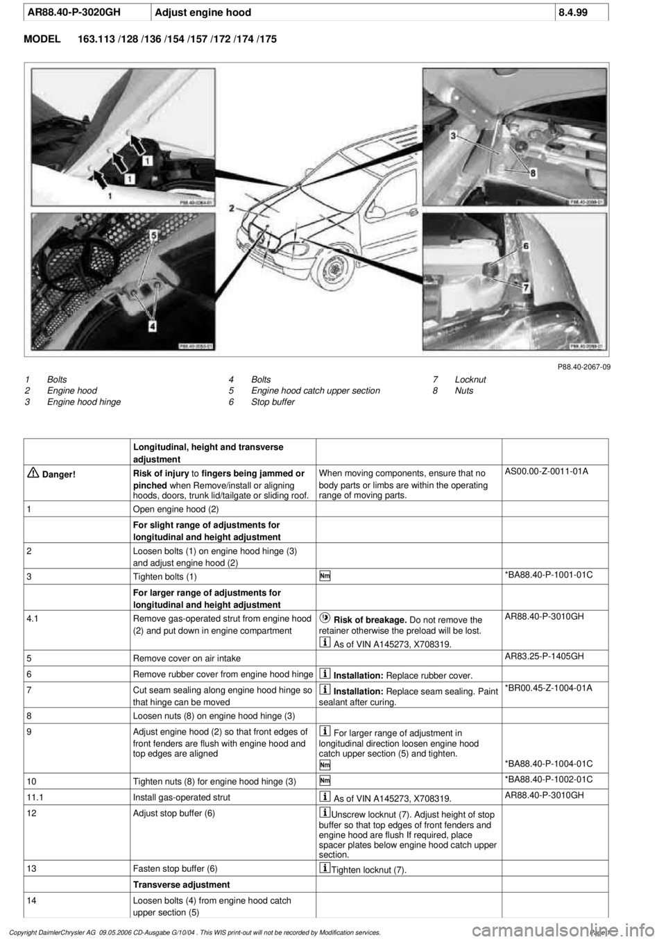
1
Bolts
2
Engine hood
3
Engine hood hinge
7
Locknut
8
Nuts
4
Bolts
5
Engine hood catch upper section
6
Stop buffer
Longitudinal, height and transverse
adjustment
Danger!
Risk of injury
to
fingers being jammed or
pinched
when Remove/install or aligning
hoods, doors, trunk lid/tailgate or sliding roof.
When moving components, ensure that no
body parts or limbs are within the operating
range of moving parts.
AS00.00-Z-0011-01A
1
Open engine hood (2)
For slight range of adjustments for
longitudinal and height adjustment
2
Loosen bolts (1) on engine hood hinge (3)
and adjust engine hood (2)
3
Tighten bolts (1)
*BA88.40-P-1001-01C
For larger range of adjustments for
longitudinal and height adjustment
4.1
Remove gas-operated strut from engine hood
(2) and put down in engine compartment
Risk of breakage. Do not remove the
retainer otherwise the preload will be lost.
AR88.40-P-3010GH
As of VIN A145273, X708319.
5
Remove cover on air intake
AR83.25-P-1405GH
6
Remove rubber cover from engine hood hinge
Installation:
Replace rubber cover.
7
Cut seam sealing along engine hood hinge so
that hinge can be moved
Installation:
Replace seam sealing. Paint
sealant after curing.
*BR00.45-Z-1004-01A
8
Loosen nuts (8) on engine hood hinge (3)
9
Adjust engine hood (2) so that front edges of
front fenders are flush with engine hood and
top edges are aligned
For larger range of adjustment in
longitudinal direction loosen engine hood
catch upper section (5) and tighten.
*BA88.40-P-1004-01C
10
Tighten nuts (8) for engine hood hinge (3)
*BA88.40-P-1002-01C
11.1
Install gas-operated strut
As of VIN A145273, X708319.
AR88.40-P-3010GH
12
Adjust stop buffer (6)
Unscrew locknut (7). Adjust height of stop
buffer so that top edges of front fenders and
engine hood are flush If required, place
spacer plates below engine hood catch upper
section.
13
Fasten stop buffer (6)
Tighten locknut (7).
Transverse adjustment
14
Loosen bolts (4) from engine hood catch
upper section (5)
Copyright DaimlerChrysler AG 09.05.2006 CD-Ausgabe G/10/04 . This WIS print-out will not be recorde
d by Modification services.
Page 1