1997 MERCEDES-BENZ ML350 height
[x] Cancel search: heightPage 3479 of 4133

BT27.00-Z-9999AZ
Technical modifications: Passenger cars: Automatic transmission
30.4.97
MODEL all
Vacuum unit for modulating pressure modified
TRANSMISSION 722.3 /5 as of 15.8.92
BT27.10-P-0001-01A
Secondary pump dispensed with
TRANSMISSION 722.5## ## as of 3652931
BT27.10-P-0002-01A
Control pressure cable with vacuum actuators
standardized
TRANSMISSION 722.3 /4 /5 as of 1.7.93
BT27.10-P-0003-01A
Sump volume modified
TRANSMISSION 722.7## ## as of 0054011
as of 29.7.99
BT27.10-P-0004-01A
Additional shim between deep-groove ball
bearing and output flange
TRANSMISSION 722 ...
BT27.10-P-0005-01A
Oil pan and overflow tube modified
TRANSMISSION 722.901
BT27.10-P-0006-01W
Retaining lug added to electrohydraulic
control module
TRANSMISSION 722.6## # as of 0026195
BT27.19-P-0001-01A
Caps for solenoid valve, new
TRANSMISSION 722.6 as of 1.8.97
BT27.19-P-0003-01A
Oil drain plug on torque converter deleted
TRANSMISSION 722.6## /6## ## as of
1772285 as of 22.9.99
BT27.20-P-0001-01A
Small intermediate plate modified
TRANSMISSION 722.5## ## as of 3987361
as of 15.3.94
BT27.35-P-0001-01A
Installation of a pressure feed valve
TRANSMISSION 722.6## # as of 0027083
BT27.35-P-0002-01A
Primary pump non-return valve dispensed with
TRANSMISSION 722.5## ## as of 3652931
BT27.35-P-0003-01A
Strainer for modulating pressure and shift
pressure control solenoid valve, new
TRANSMISSION 722.6## ## as of 0538312
BT27.35-P-0004-01A
Strainer in inlet to converter lock-up control
solenoid valve, newTRANSMISSION 722.6## ## as of 0485895
BT27.35-P-0005-01A
Feed B1 enlarged
TRANSMISSION 722.5 as of 15.8.91
BT27.40-P-0001-01A
Fluid reservoir deleted
TRANSMISSION 722.7## ## as of 0111673
as of 11.9.00
BT27.40-P-0002-01A
Magnet in oil pan, new part
TRANSMISSION 722.6## ## as of 2871384
as of 17.4.01, 722.7## ## as of 0153700 as
of 9.7.01
BT27.40-P-0003-01A
Piston B1 modified
TRANSMISSION 722.5## ## as of 3746852
as of 15.6.92, 722.3## ## as of 3969172
BT27.50-P-0002-01A
Plain bearing of input shaft changed to an anti-
friction bearing
TRANSMISSION 722 ...
BT27.50-P-0002-02A
One-way valve dispensed with
TRANSMISSION 722.5## ## as of 3652931
BT27.50-P-0007-01A
Outer multiple-disc carrier B1 modified
TRANSMISSION 722.6## # as of 0005900
BT27.50-P-0008-01A
Peak-to-valley height on piston B2 modified
TRANSMISSION 722.6## # as of 0023104
BT27.50-P-0009-01A
Piston B2 changed
TRANSMISSION 722.6## ## as of 0552036
as of 1.8.97
BT27.50-P-0010-01A
Friction bearing in sun wheel of rear planet
gear set converted to anti-friction bearing
TRANSMISSION 722 ...
BT27.50-P-0011-01A
Conversion from 18° to 23° gearing in front
and rear planetary gear system
TRANSMISSION 722 ...
BT27.50-P-0012-01A
Multi-disks for B1, K1 and K3 changed
TRANSMISSION 722.6## ## as of 3947440
as of 2.9.02
BT27.50-P-0013-01A
Thickness of friction and steel disks K3
changed
TRANSMISSION 722.6
BT27.51-P-0001-01A
Thickness of steel plates of B1, K1 and K2
modified
TRANSMISSION 722.6## ## as of 1596205
as of 15.6.99
BT27.51-P-0002-01A
Additional dished washer in multi-plate set K2
TRANSMISSION 722.6## ## as of 1596205
as of 15.6.99
BT27.51-P-0003-01A
Center shift modified
TRANSMISSION 722.6
BT27.60-P-0001-01A
Deletion shift lock cable ignition lock to
transmission
TRANSMISSION 722.7 in MODEL
WDB168.### ## as of 548031 as of 10.1.01
BT27.60-P-0001-02A
Selector lever soldered
TRANSMISSION 722.6 as of 1.5.96
BT27.60-P-0002-01A
Deletion of lever for shift lock cable ignition
lock at transmission
TRANSMISSION 722.700 ## as of 0129631
as of 24.1.01, 722.701 ## as of 0132072 as
of 8.2.01
BT27.60-P-0003-01A
Copyright DaimlerChrysler AG 28.05.2006 CD-Ausgabe G/10/04 . This WIS print-out will not be recorde
d by Modification services.
Page 1
Page 3510 of 4133
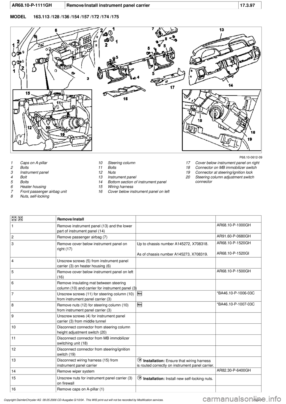
AR68.10-P-1111GH
Remove/install instrument panel carrier
17.3.97
MODEL
163.113 /128 /136 /154 /157 /172 /174 /175
P68.10-0612-09
1
Caps on A-pillar
2
Bolts
3
Instrument panel
4
Bolt
5
Bolts
6
Heater housing
7
Front passenger airbag unit
8
Nuts, self-locking
17
Cover below instrument panel on right
18
Connector on MB immobilizer switch
19
Connector at steering/ignition lock
20
Steering column adjustment switch
connector
10
Steering column
11
Bolts
12
Nuts
13
Instrument panel
14
Bottom section of instrument panel
15
Wiring harness
16
Cover below instrument panel on left
Remove/install
1
Remove instrument panel (13) and the lower
part of instrument panel (14)
AR68.10-P-1000GH
2
Remove passenger airbag (7)
AR91.60-P-0680GH
3
Remove cover below instrument panel on
right (17)
Up to chassis number A145272, X708318.
AR68.10-P-1520GH
As of chassis number A145273, X708319.
AR68.10-P-1520GI
4
Unscrew screws (5) from instrument panel
carrier (3) on heater housing (6)
5
Remove cover below instrument panel on left
(16)
AR68.10-P-1500GH
6
Remove insulating mat between steering
column (10) and carrier for instrument panel (3)
7
Unscrew screws (11) for steering column (10)
from instrument panel carrier (3)
*BA46.10-P-1006-03C
8
Remove nuts (12) for steering column (10)
from instrument panel carrier (3)
*BA46.10-P-1007-03C
9
Unscrew screws (4) for instrument panel
carrier (3) from middle tunnel
10
Disconnect connector from steering column
height adjustment switch (20)
11
Disconnect connector from MB immobilizer
switching unit (18)
12
Disconnect connector from steering/ignition
switch (19)
13
Disconnect wiring harness (15) from
instrument panel carrier
Installation:
Ensure that wiring harness
is routed correctly on instrument panel carrier.
14
Remove wiper system
AR82.30-P-6400GH
15
Unscrew nuts for instrument panel carrier (3)
on firewall
Installation:
Install new self-locking nuts.
16
Remove caps on A-pillar (1)
Copyright DaimlerChrysler AG 09.05.2006 CD-Ausgabe G/10/04 . This WIS print-out will not be recorde
d by Modification services.
Page 1
Page 3542 of 4133
Jacket tube
REMOVING AND INSTALLING CENTER AIR NOZZLE - AR68.10-P-1150GH
MODEL 163.113 /128 /136 /154 /157 /172 /174 /175
panel (3)
7Unscrew screws (11) for steering column
(10) from instrument panel carrier (3) *BA46.10-P-
1006-03C
8Remove nuts (12) for steering column (10)
from instrument panel carrier (3) *BA46.10-P-
1007-03C
9Unscrew screws (4) for instrument panel
carrier (3) from middle tunnel
10Disconnect connector from steering column
height adjustment switch (20)
11Disconnect connector from MB
immobilizer switching unit (18)
12Disconnect connector from steering/ignition
switch (19)
13Disconnect wiring harness (15) from
instrument panel carrier Installation:Ensure that wiring
harness is routed correctly on
instrument panel carrier.
14Remove wiper system AR82.30-P-
6400GH
15Unscrew nuts for instrument panel carrier
(3) on firewall Installation: Install new self-
locking nuts.
16Remove caps on A-pillar (1)
17Unscrew screws (2) for instrument panel
carrier (3) from A-pillar
18
Remove instrument panel carrier (3) and
take out of passenger compartment to side
through passenger doorBe careful not to damage center
console when removing and
installing.
19Install in the reverse order
NumberDesignationMODEL Series
163
BA46.10-P-1006-
03CScrew for jacket tube on upper instrument panel carrierNm20
BA46.10-P-1007-
03CJacket tube collar nut on instrument panel carrier at
bottomNm18
2001 Mercedes-Benz ML320
1998-2005 ACCESSORIES & BODY, CAB Interior Equipment - 163 Chassis
me
Saturday, October 02, 2010 3:35:21 PMPage 24 © 2006 Mitchell Repair Information Company, LLC.
Page 3587 of 4133
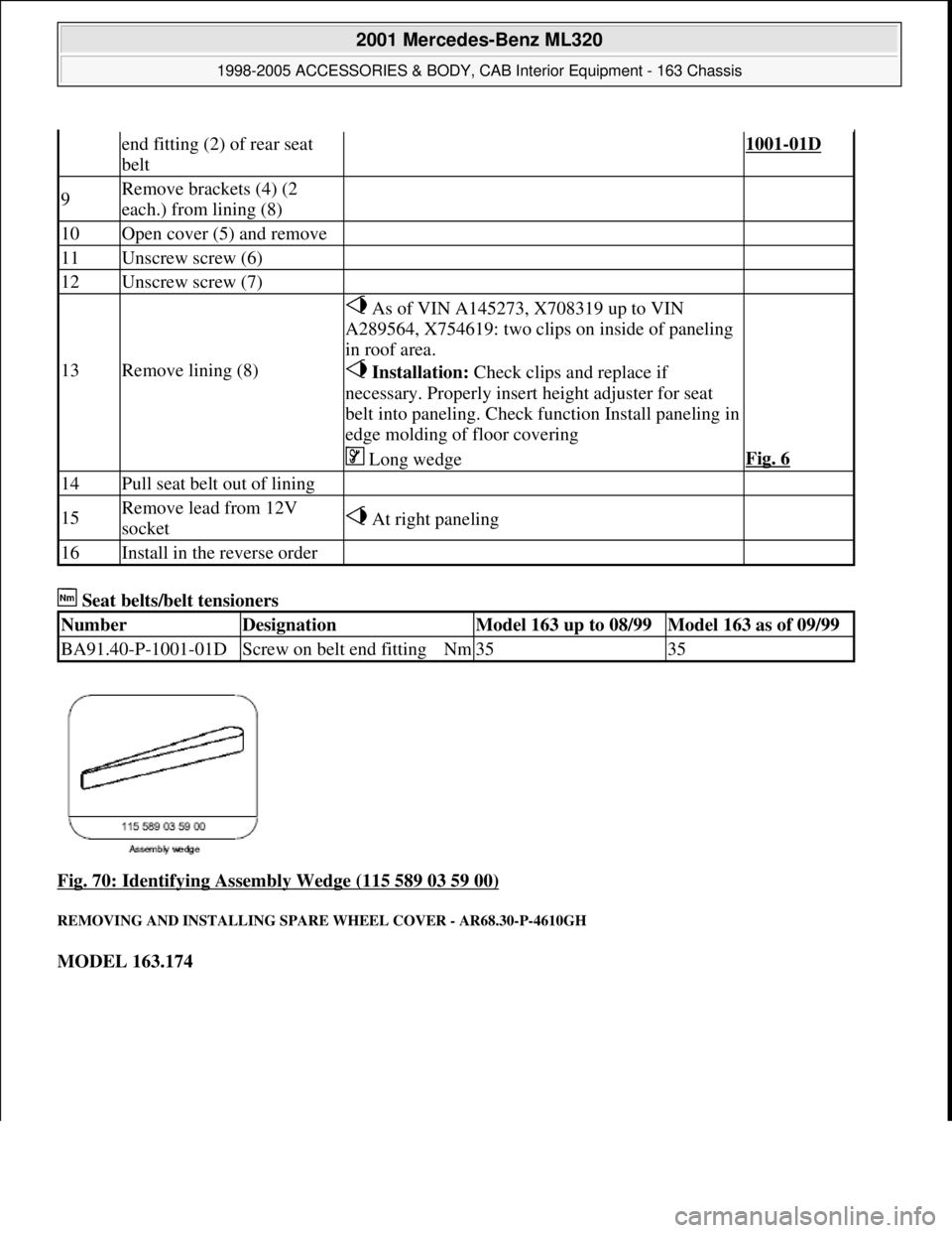
Seat belts/belt tensioners
Fig. 70: Identifying Assembly Wedge (115 589 03 59 00)
REMOVING AND INSTALLING SPARE WHEEL COVER - AR68.30-P-4610GH
MODEL 163.174
end fitting (2) of rear seat
belt1001-01D
9Remove brackets (4) (2
each.) from lining (8)
10Open cover (5) and remove
11Unscrew screw (6)
12Unscrew screw (7)
13Remove lining (8)
As of VIN A145273, X708319 up to VIN
A289564, X754619: two clips on inside of paneling
in roof area.
Installation: Check clips and replace if
necessary. Properly insert height adjuster for seat
belt into paneling. Check function Install paneling in
edge molding of floor covering
Long wedgeFig. 6
14Pull seat belt out of lining
15Remove lead from 12V
socket At right paneling
16Install in the reverse order
NumberDesignationModel 163 up to 08/99Model 163 as of 09/99
BA91.40-P-1001-01DScrew on belt end fittingNm3535
2001 Mercedes-Benz ML320
1998-2005 ACCESSORIES & BODY, CAB Interior Equipment - 163 Chassis
me
Saturday, October 02, 2010 3:35:22 PMPage 69 © 2006 Mitchell Repair Information Company, LLC.
Page 3789 of 4133

AR91.29-P-0008GH
Remove/install seat adjustment control module
23.6.99
MODEL
163.113 /128,
163.136 /154 as of 1.9.99,
163.157,
163.172 as of 1.9.99,
163.175
with CODE (241) Memory for electrically adjustable left front seat
with CODE (242a) Memory for electrically adjustable right front seat
MODEL
163.174
P91.29-2108-06
1
Coupling for left front seat
adjustment switch or right front seat
adjustment switch
2
Coupling for interior wiring harness
3
Coupling for height adjustment
motor for rear front seat cushion
4
Coupling for horizontal adjustment
motor for front seat
5
Coupling for height adjustment
motor for front front seat cushion
6
Coupling for electrical line for seat
belt buckle of front seat
P91.29-2108-06
7
Coupling for front seat backrest
angle motor
8
Coupling for automatic child seat
recognition
9
Coupling for heated seats
10
Bracket
11
Retaining lugs
N32/1
Left front seat adjustment control
module with memory
N32/2
Right front seat adjustment control
module with memory
Remove/Install
1
Move front seat forwards and adjust rear front
seat cushion upwards
2
Disconnect connector from coupling for left
front seat adjustment switch or right front seat
adjustment switch (1) and from the coupling
for interior wiring harness (2) on the left front
seat adjustment control module with memory
(N32/1) or right front seat adjustment control
module with memory (N32/2)
Copyright DaimlerChrysler AG 14.06.2006 CD-Ausgabe G/10/04 . This WIS print-out will not be recorde
d by Modification services.
Page 1
Page 3798 of 4133
GF91.29-P-0002GH
Electric seat adjustment with memory, function
14.7.99
MODEL
163 as of 1.1.00
with CODE (241) Memory for electrically adjustable left front seat
with CODE (242a) Memory for electrically adjustable right front seat
P91.29-2114-11
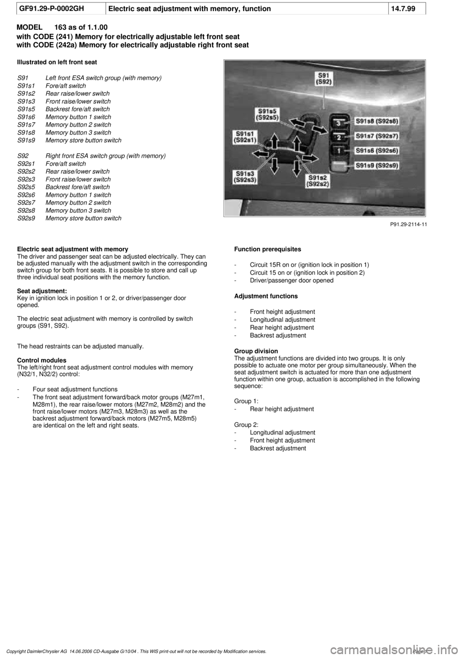
Illustrated on left front seat
S91
Left front ESA switch group (with memory)
S91s1
Fore/aft switch
S91s2
Rear raise/lower switch
S91s3
Front raise/lower switch
S91s5
Backrest fore/aft switch
S91s6
Memory button 1 switch
S91s7
Memory button 2 switch
S91s8
Memory button 3 switch
S91s9
Memory store button switch
S92
Right front ESA switch group (with memory)
S92s1
Fore/aft switch
S92s2
Rear raise/lower switch
S92s3
Front raise/lower switch
S92s5
Backrest fore/aft switch
S92s6
Memory button 1 switch
S92s7
Memory button 2 switch
S92s8
Memory button 3 switch
S92s9
Memory store button switch
Electric seat adjustment with memory
The driver and passenger seat can be adjusted electrically. They can
be adjusted manually with the adjustment switch in the corresponding
switch group for both front seats. It is possible to store and call up
three individual seat positions with the memory function.
Seat adjustment:
Key in ignition lock in position 1 or 2, or driver/passenger door
opened.
The electric seat adjustment with memory is controlled by switch
groups (S91, S92).
The head restraints can be adjusted manually.
Control modules
The left/right front seat adjustment control modules with memory
(N32/1, N32/2) control:
-
Four seat adjustment functions
-
The front seat adjustment forward/back motor groups (M27m1,
M28m1), the rear raise/lower motors (M27m2, M28m2) and the
front raise/lower motors (M27m3, M28m3) as well as the
backrest adjustment forward/back motors (M27m5, M28m5)
are identical on the left and right seats.
Function prerequisites
-
Circuit 15R on or (ignition lock in position 1)
-
Circuit 15 on or (ignition lock in position 2)
-
Driver/passenger door opened
Adjustment functions
-
Front height adjustment
-
Longitudinal adjustment
-
Rear height adjustment
-
Backrest adjustment
Group division
The adjustment functions are divided into two groups. It is only
possible to actuate one motor per group simultaneously. When the
seat adjustment switch is actuated for more than one adjustment
function within one group, actuation is accomplished in the following
sequence:
Group 1:
-
Rear height adjustment
Group 2:
-
Longitudinal adjustment
-
Front height adjustment
-
Backrest adjustment
Copyright DaimlerChrysler AG 14.06.2006 CD-Ausgabe G/10/04 . This WIS print-out will not be recorde
d by Modification services.
Page 1
Page 3801 of 4133
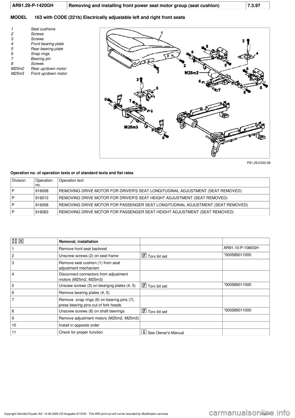
AR91.29-P-1420GH
Removing and installing front power seat motor group (seat cushion)
7.3.97
MODEL
163 with CODE (221b) Electrically adjustable left and right front seats
P91.29-0333-06
1
Seat cushions
2
Screws
3
Screws
4
Front bearing plate
5
Rear bearing plate
6
Snap rings
7
Bearing pin
8
Screws
M25m2
Rear up/down motor
M25m3
Front up/down motor
Operation no. of operation texts or of standard texts and flat rates
Division
Operation
no.
Operation text
P
916008
REMOVING DRIVE MOTOR FOR DRIVER'S SEAT LONGITUDINAL ADJUSTMENT (SEAT REMOVED)
P
916013
REMOVING DRIVE MOTOR FOR DRIVER'S SEAT HEIGHT ADJUSTMENT (SEAT REMOVED)
P
916058
REMOVING DRIVE MOTOR FOR PASSENGER SEAT LONGITUDINAL ADJUSTMENT (SEAT REMOVED)
P
916063
REMOVING DRIVE MOTOR FOR PASSENGER SEAT HEIGHT ADJUSTMENT (SEAT REMOVED)
Removal, installation
1
Remove front seat backrest
AR91.10-P-1060GH
2
Unscrew screws (2) on seat frame
Torx bit set
*000589011000
3
Remove seat cushion (1) from seat
adjustment mechanism
4
Disconnect connectors from adjustment
motors (M25m2, M25m3)
5
Unscew screws (3) on bearigng plates (4, 5)
Torx bit set
*000589011000
6
Remove bearing plates (4, 5)
7
Remove snap rings (6) on bearing pins (7),
press bearing pins out of fork heads
8
Unscrew screws (8) on shaft beerings
Torx bit set
*000589011000
9
Remove adjustment motors (M25m2, M25m3)
10
Install in opposite order
11
Check for proper function
See Owner's Manual
Copyright DaimlerChrysler AG 14.06.2006 CD-Ausgabe G/10/04 . This WIS print-out will not be recorde
d by Modification services.
Page 1
Page 3803 of 4133

AR91.10-P-1000GH
Remove/install front seat
3.3.97
MODEL
163.113 /128 /136 /154 /157 /172 /174 /175 with CODE (221b) Electrically adjustable driver and passe
nger seat
P91.10-0547-06
1
Torx socket screws
2
Cover cap
3
Front seat
4
Torx socket bolt
5
Belt end fitting
6
Connector
X55/3
Left front seat contacting strip
X55/4
Right front seat connector block
Remove/install
1
Remove headrest
See owner's manual
2
Remove cover cap (2) from seat rail paneling
Set the seat height adjustment such that
the screw on the belt end fitting is visible.
3
Unscrew internal Torx drive bolt (4) from the
belt end fitting (5)
*BA91.40-P-1001-01D
Torx bit set
*000589011000
4
Remove belt end fitting (5)
5
Unscrew internal Torx drive bolts (1) from the
front seat console
Installation:
Replace bolts.
*BA91.10-P-1001-01B
Torx bit set
*000589011000
6
Move the front seat (3) forward
7
Unscrew internal Torx drive bolts (1) from the
back seat console
Installation:
Replace bolts.
*BA91.10-P-1001-01B
Torx bit set
*000589011000
8
Detach connector (6) from the front left seat
connector block (X55/3) and the front right
seat connector block (X55/4)
9
Remove front seat (3)
10
Install in the reverse order
Front seats
Number
Designation
Model
Series 163
BA91.10-P-1001-01BBolt of seating mounting bracket to vehicle
floor
Nm
40
Safety belts/emergency tensioning retractors
Copyright DaimlerChrysler AG 09.05.2006 CD-Ausgabe G/10/04 . This WIS print-out will not be recorde
d by Modification services.
Page 1