1997 MERCEDES-BENZ ML350 height
[x] Cancel search: heightPage 3818 of 4133

2
Withdraw ignition key
3
Unclip cap (1) from outer paneling (3)
4
Unscrew bolt (2) from belt end fitting (4)
*BA91.40-P-1001-01D
Torx bit set
*000589011000
5
Pull belt end fitting (4) out of front seat
6
Remove paneling on B-pillar
AR68.30-P-4700GH
7
Unscrew bolt (5) of belt height adjuster from
B-pillar
*BA91.40-P-1004-01D
8
Disconnect connector from passenger ETR
[GUS] ignition squib (R12/2)
9
Unscrew bolt (6) from automatic belt retractor
(7)
*BA91.40-P-1008-01D
Torx bit set
*000589011000
10
Detach automatic belt retractor (7)
The automatic belt retractor must not be
disassembled.
Never use oil or grease to eliminate noises.
Automatic belt retractors that have been
opened are no longer under warranty!
11
Check seat belt for signs of damage
e
Check seat belts for damage
AP91.40-P-9150GH
12
Install in the reverse order
Installation:
Pay attention to different
version (left/ right) of emergency tensioning
retractors and satisfactory seating in the
locking device.
13
Read fault memory and erase
14Carry out diagnosis
see Diagnosis Manual.
Seat belts/emergency tensioning retractors
Number
Designation
Model 163 up to
08/99
Model 163 as of
09/99
BA91.40-P-1001-01D
Screw on belt end fitting
Nm
3535
BA91.40-P-1004-01D
Bolt to belt height adjuster
Nm
2525
BA91.40-P-1008-01DScrew on front automatic belt reel
Nm
30 (+10/-0.15)30 (+10/-0.15)
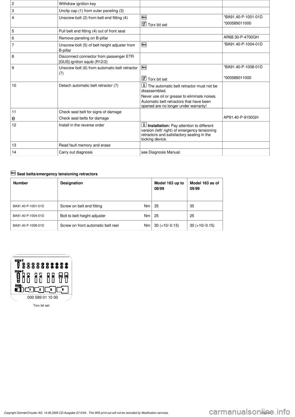
Torx bit set
000 589 01 10 00
Copyright DaimlerChrysler AG 14.06.2006 CD-Ausgabe G/10/04 . This WIS print-out will not be recorde
d by Modification services.
Page 2
Page 3819 of 4133

AR91.40-P-0681GI
Remove/install rear seat belts
16.4.99
MODEL
163.136 /154 /172 as of 1.9.99,
163.113 /128 /157 /174 /175
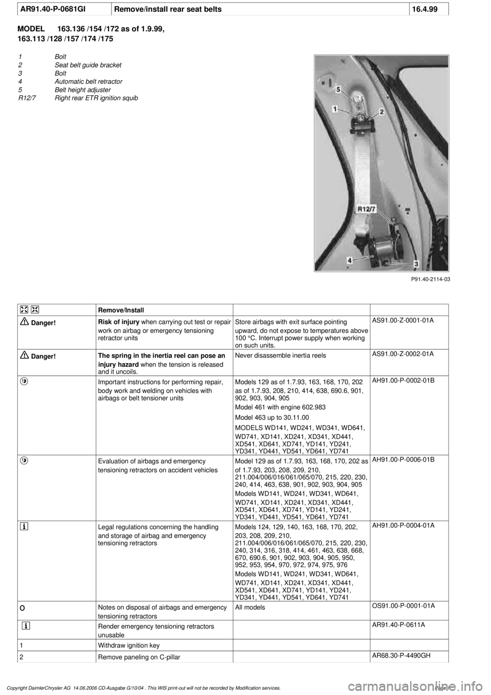
1
Bolt
2
Seat belt guide bracket
3
Bolt
4
Automatic belt retractor
5
Belt height adjuster
R12/7
Right rear ETR ignition squib
P91.40-2114-03
Remove/Install
Danger!
Risk of injury
when carrying out test or repair
work on airbag or emergency tensioning
retractor units
Store airbags with exit surface pointing
upward, do not expose to temperatures above
100 °C. Interrupt power supply when working
on such units.
AS91.00-Z-0001-01A
Danger!
The spring in the inertia reel can pose an
injury hazard
when the tension is released
and it uncoils.
Never disassemble inertia reels
AS91.00-Z-0002-01A
Important instructions for performing repair,
body work and welding on vehicles with
airbags or belt tensioner units
Models 129 as of 1.7.93, 163, 168, 170, 202
as of 1.7.93, 208, 210, 414, 638, 690.6, 901,
902, 903, 904, 905
Model 461 with engine 602.983
Model 463 up to 30.11.00
MODELS WD141, WD241, WD341, WD641,
WD741, XD141, XD241, XD341, XD441,
XD541, XD641, XD741, YD141, YD241,
YD341, YD441, YD541, YD641, YD741
AH91.00-P-0002-01B
Evaluation of airbags and emergency
tensioning retractors on accident vehicles
Model 129 as of 1.7.93, 163, 168, 170, 202 as
of 1.7.93, 203, 208, 209, 210,
211.004/006/016/061/065/070, 215, 220, 230,
240, 414, 463, 638, 901, 902, 903, 904, 905
Models WD141, WD241, WD341, WD641,
WD741, XD141, XD241, XD341, XD441,
XD541, XD641, XD741, YD141, YD241,
YD341, YD441, YD541, YD641, YD741
AH91.00-P-0006-01B
Legal regulations concerning the handling
and storage of airbag and emergency
tensioning retractors
Models 124, 129, 140, 163, 168, 170, 202,
203, 208, 209, 210,
211.004/006/016/061/065/070, 215, 220, 230,
240, 314, 316, 318, 414, 461, 463, 638, 668,
670, 690.6, 901, 902, 903, 904, 905, 950,
952, 953, 954, 970, 972, 974, 975, 976
Models WD141, WD241, WD341, WD641,
WD741, XD141, XD241, XD341, XD441,
XD541, XD641, XD741, YD141, YD241,
YD341, YD441, YD541, YD641, YD741
AH91.00-P-0004-01A
o
Notes on disposal of airbags and emergency
tensioning retractors
All models
OS91.00-P-0001-01A
Render emergency tensioning retractors
unusable
AR91.40-P-0611A
1
Withdraw ignition key
2
Remove paneling on C-pillar
AR68.30-P-4490GH
Copyright DaimlerChrysler AG 14.06.2006 CD-Ausgabe G/10/04 . This WIS print-out will not be recorde
d by Modification services.
Page 1
Page 3820 of 4133
![MERCEDES-BENZ ML350 1997 Complete Repair Manual 3
Unscrew bolt (1) from seat belt guide bracket
(2)
If necessary, remove belt height adjuster
(5).
*BA91.40-P-1002-01D
4
Disconnect connector from right rear ETR
[GUS] ignition squib (R12/7 MERCEDES-BENZ ML350 1997 Complete Repair Manual 3
Unscrew bolt (1) from seat belt guide bracket
(2)
If necessary, remove belt height adjuster
(5).
*BA91.40-P-1002-01D
4
Disconnect connector from right rear ETR
[GUS] ignition squib (R12/7](/manual-img/4/57306/w960_57306-3819.png)
3
Unscrew bolt (1) from seat belt guide bracket
(2)
If necessary, remove belt height adjuster
(5).
*BA91.40-P-1002-01D
4
Disconnect connector from right rear ETR
[GUS] ignition squib (R12/7)
5
Unscrew bolt (3) from automatic belt retractor
(4)
*BA91.40-P-1003-01D
6
Detach automatic belt retractor (4)
The automatic belt retractor must not be
disassembled.
Never use oil or grease to eliminate noises.
7
Check seat belts for damage
e
Check seat belts for damage
AP91.40-P-9150GH
8
Install in the reverse order
Installation:
Pay attention to different
version (left/ right) of emergency tensioning
retractors and satisfactory seating in the
locking device.
9
Read fault memory and erase
10Carry out diagnosis
see Diagnosis Manual.
Seat belts/emergency tensioning retractors
Number
Designation
Model 163 up to
08/99
Model 163 as of
09/99
BA91.40-P-1002-01D
Screw in rear upper belt guide fitting
Nm
3030
BA91.40-P-1003-01D
Bolt to rear inertia reel
Nm
3030
Copyright DaimlerChrysler AG 14.06.2006 CD-Ausgabe G/10/04 . This WIS print-out will not be recorde
d by Modification services.
Page 2
Page 3829 of 4133

AR91.40-P-0681GH
Removing and installing rear seat belts
13.3.97
MODELS
163.136 /154 /172 up to 31.8.99
P91.40-0360-06
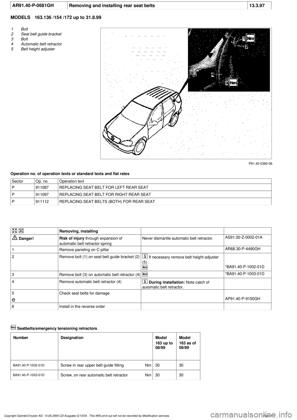
1
Bolt
2
Seat belt guide bracket
3
Bolt
4
Automatic belt retractor
5
Belt height adjuster
Operation no. of operation texts or standard texts and flat rates
Sector
Op. no.
Operation text
P
911087
REPLACING SEAT BELT FOR LEFT REAR SEAT
P
911097
REPLACING SEAT BELT FOR RIGHT REAR SEAT
P
911112
REPLACING SEAT BELTS (BOTH) FOR REAR SEAT
Removing, installing
Danger!
Risk of injury
through expansion of
automatic belt retractor spring
Never dismantle automatic belt retractor.
AS91.00-Z-0002-01A
1
Remove paneling on C-pillar
AR68.30-P-4490GH
2
Remove bolt (1) on seat belt guide bracket (2)
If necessary remove belt height adjuster
(5) .
*BA91.40-P-1002-01D
3
Remove bolt (3) on automatic belt retractor (4)
*BA91.40-P-1003-01D
4
Remove automatic belt retractor (4)
During installation:
Note catch of
automatic belt retractor.
5
Check seat belts for damage
e
AP91.40-P-9150GH
6
Install in the reverse order
Seatbelts/emergency tensioning retractors
Number
Designation
Model
163 up to
08/99
Model
163 as of
09/99
BA91.40-P-1002-01D
Screw in rear upper belt guide fitting
Nm
3030
BA91.40-P-1003-01D
Screw, on rear automatic belt retractorNm
3030
Copyright DaimlerChrysler AG 14.06.2006 CD-Ausgabe G/10/04 . This WIS print-out will not be recorde
d by Modification services.
Page 1
Page 3905 of 4133

AR88.30-P-0200-02GH
Prepare body
Commercially available tools
(see Workshop Equipment Manual)
Number
Designation
Make (e. g.)
Order number
WH58.30-Z-1010-10A
Cutting tool kit (compressed-air tool + blades)
Europe:
The Barn
Holly Tree Farm
Holmes Chapel Road
Lower Withington,
Cheshire, SK11 9DT
England
Tel.:
+44 1477 571700
Japan:
Osaka Chamber of
Commerce
2-8 Hommachibashi
Chuo-ku
Osaka, Japan, 540-
0029
Tel.:+81 6 6944 6445
USA:
SPX
Dealer Equipment
Services Tel.:
+1-888-458-4040
P88.30-2115-01
Do not allow blade to touch paint to avoid scratches.Do not touch surface of remaining bead
of glue after cutting through, because this has a negative effect on the adherence. After cutting
through the bead of glue, do not wait longer than 6-8 hours to complete the repair. If it is not
possible to complete the repair within this time, apply Beta primer 5404 to the remaining bead of
glue to achieve good adhesion.
1
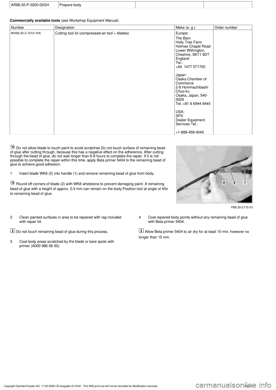
Insert blade WK6 (2) into handle (1) and remove remaining bead of glue from body.
Round off corners of blade (2) with WK8 whetstone to prevent damaging paint. A remaining
bead of glue with a height of approx. 0.5 mm can remain on the body.Position tool at angle of 45
o
to remaining bead of glue.
2
Clean painted surfaces in area to be repaired with rag included
with repair kit.
Do not touch remaining bead of glue during this process.
3
Coat body areas scratched by the blade or bare spots with
primer (A000 986 06 50).
4
Coat repaired body points without any remaining bead of glue
with Beta primer 5404. Allow Beta primer 5404 to air dry for at least 10 min, however no
longer than 15 min.
Copyright DaimlerChrysler AG 17.05.2006 CD-Ausgabe G/10/04 . This WIS print-out will not be recorde
d by Modification services.
Page 1
Page 3983 of 4133

10
Remove edge guard for tilting/sliding roof
cutout
11
Release upper right B-pillar paneling
12
Remove covers at lower rear seat
Do NOT remove center cover for lower
40% seat. Do NOT reinstall curtain on 60%
front bench seat.
f
Remove and install cover on bottom of rear
seat
AR91.12-P-1100GH
13
Release side shade at the 60% bench
Fold shade upward so that the working
area is not obstructed.
14
Remove 40% rear seat
f
Remove and install bench
AR91.12-P-1010GI
Torx bit set
*000589011000
Install
15
Retrofit central interface module (1)
AZ82.60-P-0004-01A
16
Insert antenna cable for FM modulator (6) into
vehicle antenna cable (7)
17
Cover connector with self-adhesive foamed
material (8)
18
Plug remaining antenna cable of FM
modulator (9) into radio
19
Install radio (A2)
f
Remove/install radio
AR82.60-P-7502EA
20
Retrofit video monitor (2) and wiring harness
of video monitor (C)
With
glass version of electric sliding/tilting
roof, code 414a.
AZ82.60-P-0004-02A
Except
glass version of electric
sliding/tilting roof, code 414a.
AZ82.60-P-0004-02B
21
Secure upper right B-pillar paneling
Ensure that the lugs of the seat belt height
adjustment are located correctly in the recess
clearance of the paneling.
22
Install right front handle
23
Install right sun visor
f
Remove/install sun visor
AR68.60-P-5480GH
24
Install right front A-pillar cover
f
Remove/install paneling on A-pillar
AR68.30-P-4050GH
25
Re-secure upper area of rubber door seal
26
Route wiring harness of video/DVD player
(B), additional interface module (4) and wiring
harness of video monitor (C) later
Up to VIN A289564, X754619.
AZ82.60-P-0004-03A
As of VIN A289565, X754620.
AZ82.60-P-0004-03B
27
Retrofit auxiliary interface module (4) in
center console
Up to VIN A289564, X754619.
AZ82.60-P-0004-04A
As of VIN A289565, X754620.
AZ82.60-P-0004-04B
28
Install center console insulating mat
29
Install center console
f
Remove/install center console
AR68.20-P-2000GH
30.1
Plug in plug of additional interface module
and secure the wiring harness of the
additional interface module (10) to the clip
(11) together with the wiring harness of the
rear power windows in the center console
Up to VIN A289564, X754619.
30.2
Insert auxiliary interface module (13)
connector and route between center console
mount (14) and center console.
As of VIN A289565, X754620.
31.1
Secure auxiliary interface module plug in the
left rear corner of the ashtray housing using
self-adhesive foamed material (12)
Up to VIN A289564, X754619.
32
Open ashtray and cup holder and close to
check correct function
33
Attach side shade of the 60% bench
34.1
Retrofit video player (3)
AZ82.60-P-0004-05A
*BA91.12-P-1005-03A
*BA91.12-P-1008-03A
34.2
Retrofit DVD player
AZ82.60-P-0005-01GH
35
Install 40% rear seat
f
Remove and install bench
AR91.12-P-1010GI
Torx bit set
*000589011000
Copyright DaimlerChrysler AG 09.05.2006 CD-Ausgabe G/10/04 . This WIS print-out will not be recorde
d by Modification services.
Page 2