1997 MERCEDES-BENZ ML350 height
[x] Cancel search: heightPage 1968 of 4133
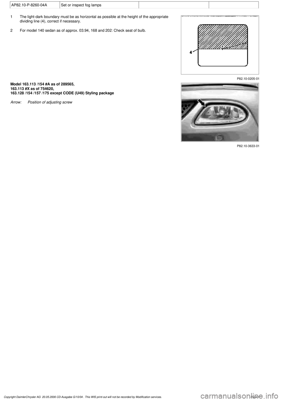
AP82.10-P-8260-04A
Set or inspect fog lamps
P82.10-0205-01
1
The light-dark boundary must be as horizontal as possible at the height of the appropriate
dividing line (4), correct if necessary.
2
For model 140 sedan as of approx. 03.94, 168 and 202: Check seat of bulb.
P82.10-3633-01
Model 163.113 /154 #A as of 289565,
163.113 #X as of 754620,
163.128 /154 /157 /175 except CODE (U49) Styling package
Arrow:
Position of adjusting screw
Copyright DaimlerChrysler AG 20.05.2006 CD-Ausgabe G/10/04 . This WIS print-out will not be recorde
d by Modification services.
Page 1
Page 1970 of 4133
AP82.10-P-8260GH
Check and correct headlamp adjustment
2.7.97
MODEL
163
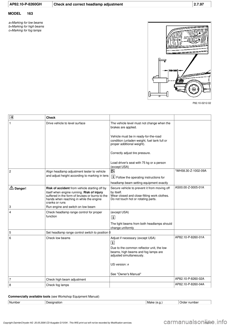
a=Marking for low beams
b=Marking for high beams
c=Marking for fog lamps
P82.10-0212-02
Check
1
Drive vehicle to level surface
The vehicle level must not change when the
brakes are applied.
Vehicle must be in ready-for-the-road
condition (unladen weight, fuel tank full or
proper additional weight).
Correctly adjust tire pressure.
Load driver's seat with 75 kg or a person
(except USA)
2
Align headlamp adjustment tester to vehicle
and adjust height according to marking in lens
Follow the operating instructions for
headlamp beam setting equipment exactly
*WH58.30-Z-1002-09A
Danger!
Risk of accident
from vehicle starting off by
itself when engine running.
Risk of injury
suffered in the form of bruises or burns to the
hands when reaching in while the engine
cranks or runs
Secure vehicle to prevent it from moving off
by itself.
Wear closed and close-fitting work clothes.
Do not touch hot or rotating parts.
AS00.00-Z-0005-01A
3
Run engine and switch on low beam
4
Check headlamp range control for proper
function
(except USA)
The light beams from both headlamps should
change uniformly
5
Set headlamp range control switch to position 0
6
Check low beams
Adjust if necessary (except USA)
AP82.10-P-8260-01A
Due to the common reflector unit, the low
beams, high beams and fog lamps are
adjusted simultaneously.
US version:
#
See "Owner's Manual"
7
Check high beam adjustment
AP82.10-P-8260-02A
8
Check fog lamps
AP82.10-P-8260-04A
Commercially available tools
(see Workshop Equipment Manual)
Number
Designation
Make (e.g.)
Order number
Copyright DaimlerChrysler AG 20.05.2006 CD-Ausgabe G/10/04 . This WIS print-out will not be recorde
d by Modification services.
Page 1
Page 2131 of 4133
AR63.20-P-2010GH
Remove/install D-pillar paneling
26.1.99
MODEL
163.113 /128 /136 /154 /157 /172 /174 /175
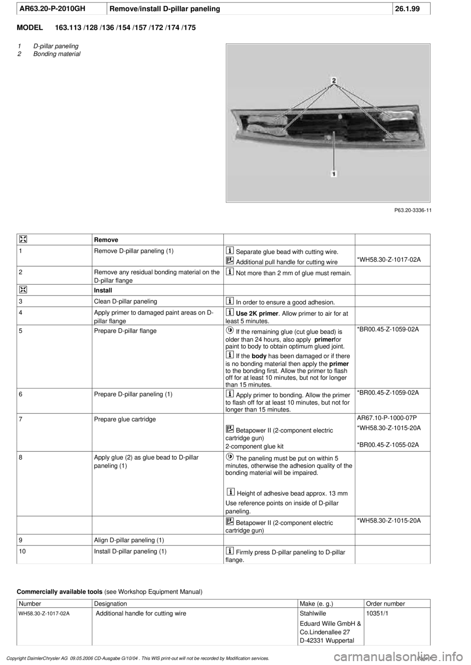
P63.20-3336-11
1
D-pillar paneling
2
Bonding material
Remove
1
Remove D-pillar paneling (1)
Separate glue bead with cutting wire.
Additional pull handle for cutting wire
*WH58.30-Z-1017-02A
2
Remove any residual bonding material on the
D-pillar flange
Not more than 2 mm of glue must remain.
Install
3
Clean D-pillar paneling
In order to ensure a good adhesion.
4
Apply primer to damaged paint areas on D-
pillar flange
Use 2K primer
. Allow primer to air for at
least 5 minutes.
5
Prepare D-pillar flange
If the remaining glue (cut glue bead) is
older than 24 hours, also apply
primer
for
paint to body to obtain optimum glued joint.
*BR00.45-Z-1059-02A
If the
body
has been damaged or if there
is no bonding material then apply the
primer
to the bonding first. Allow the primer to flash
off for at least 10 minutes, but not for longer
than 15 minutes.
6
Prepare D-pillar paneling (1)
Apply primer to bonding. Allow the primer
to flash off for at least 10 minutes, but not for
longer than 15 minutes.
*BR00.45-Z-1059-02A
7
Prepare glue cartridge
AR67.10-P-1000-07P
Betapower II (2-component electric
cartridge gun)
*WH58.30-Z-1015-20A
2-component glue kit
*BR00.45-Z-1055-02A
8
Apply glue (2) as glue bead to D-pillar
paneling (1)
The paneling must be put on within 5
minutes, otherwise the adhesion quality of the
bonding material will be impaired.
Height of adhesive bead approx. 13 mm
Use reference points on inside of D-pillar
paneling.
Betapower II (2-component electric
cartridge gun)
*WH58.30-Z-1015-20A
9
Align D-pillar paneling (1)
10
Install D-pillar paneling (1)
Firmly press D-pillar paneling to D-pillar
flange.
Commercially available tools
(see Workshop Equipment Manual)
Number
Designation
Make (e. g.)
Order number
WH58.30-Z-1017-02A
Additional handle for cutting wire
Stahlwille
Eduard Wille GmbH &
Co.Lindenallee 27
D-42331 Wuppertal
10351/1
Copyright DaimlerChrysler AG 09.05.2006 CD-Ausgabe G/10/04 . This WIS print-out will not be recorde
d by Modification services.
Page 1
Page 2328 of 4133
DriftFig. 78
6Remove cylinder head
(1) from assembly
board (2)
Risk of explosion
and poisoning caused
by the melting down
or improper handling
of sodium-filled
valves. Risk of injury
caused by skin contact
with sodium resulting
in heat or chemical
burns.Do not open sodium-filled valves.
Wear protective gloves and safety
glasses when handling damaged
valves.AS05.30-Z-0001-01A
7Remove valve (14) Installation: Check surface of
valve stems for roughness and
formation of ridging (visual
inspection or with a nail). Replace
valves (14) with a rough stem
surface or formation of burrs. Grind
new or reused valves (14) with valve
grinding compound before
installation.
Disposal of sodium-
filled valvesExhaust valves with sodium fillingOS05.30-P-0001-01A
Checking
8Check valves (14) Intake and exhaust valves must
not be machined.
If the specified tolerances are
below the required limit, the valve
(14) must be replaced to ensure
functioning.AR05.30-P-4201-
01AV
Valve disk ø*BE05.30-P-1001-
01E
Valve disk height*BE05.30-P-1002-
01E
Valve seat angle (a)*BE05.30-P-1003-
01E
Valve stem ø*BE05.30-P-1004-
01E
Valve length*BE05.30-P-1005-
01E
9Inspect valve guides,
replace if necessary AR05.30-P-3731AV
10Install in the reverse
2004 Mercedes-Benz ML350
1998-2005 ENGINE Engine timing - 163 Chassis
me
Saturday, October 02, 2010 3:39:38 PMPage 87 © 2006 Mitchell Repair Information Company, LLC.
Page 2329 of 4133
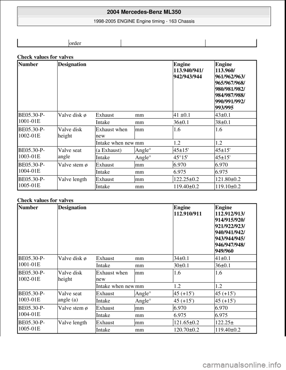
Check values for valves
Check values for valves
order
NumberDesignationEngine
113.940/941/
942/943/944Engine
113.960/
961/962/963/
965/967/968/
980/981/982/
984/987/988/
990/991/992/
993/995
BE05.30-P-
1001-01EValve disk øExhaustmm41 ±0.143±0.1
Intakemm36±0.138±0.1
BE05.30-P-
1002-01EValve disk
heightExhaust when
newmm1.61.6
Intake when newmm1.21.2
BE05.30-P-
1003-01EValve seat
angle(a Exhaust)Angle°45±15'45±15'
IntakeAngle°45°15'45±15'
BE05.30-P-
1004-01EValve stem øExhaustmm6.9706.970
Intakemm6.9756.975
BE05.30-P-
1005-01EValve lengthExhaustmm122.25±0.2121.80±0.2
Intakemm119.40±0.2119.10±0.2
NumberDesignationEngine
112.910/911Engine
112.912/913/
914/915/920/
921/922/923/
940/941/942/
943/944/945/
946/947/948/
949/960
BE05.30-P-
1001-01EValve disk øExhaustmm34±0.141±0.1
Intakemm30±0.136±0.1
BE05.30-P-
1002-01EValve disk
heightExhaust when
newmm1.61.6
Intake when newmm1.21.2
BE05.30-P-
1003-01EValve seat
angle (a)ExhaustAngle°45 (+15')45 (+15')
IntakeAngle°45 (+15')45 (+15')
BE05.30-P-
1004-01EValve stem øExhaustmm6.9706.970
Intakemm6.9756.975
BE05.30-P-
1005-01EValve lengthExhaustmm121.65±0.2122.25±
Intakemm120.70±0.2119.40±0.2
2004 Mercedes-Benz ML350
1998-2005 ENGINE Engine timing - 163 Chassis
me
Saturday, October 02, 2010 3:39:38 PMPage 88 © 2006 Mitchell Repair Information Company, LLC.
Page 2344 of 4133
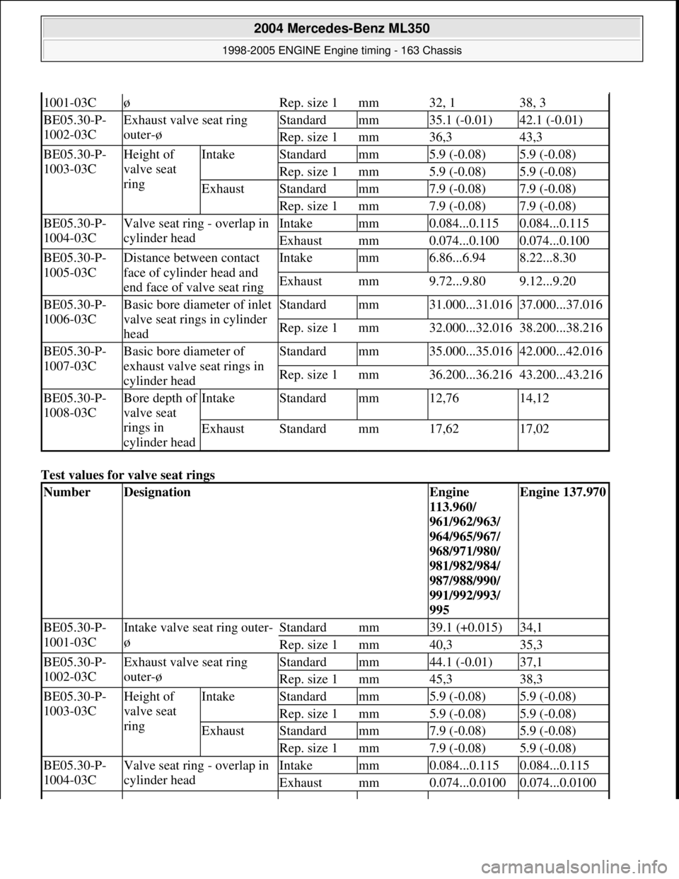
Test values for valve seat rings
1001-03CøRep. size 1mm32, 138, 3
BE05.30-P-
1002-03CExhaust valve seat ring
outer-øStandardmm35.1 (-0.01)42.1 (-0.01)
Rep. size 1mm36,343,3
BE05.30-P-
1003-03CHeight of
valve seat
ringIntakeStandardmm5.9 (-0.08)5.9 (-0.08)
Rep. size 1mm5.9 (-0.08)5.9 (-0.08)
ExhaustStandardmm7.9 (-0.08)7.9 (-0.08)
Rep. size 1mm7.9 (-0.08)7.9 (-0.08)
BE05.30-P-
1004-03CValve seat ring - overlap in
cylinder headIntakemm0.084...0.1150.084...0.115
Exhaustmm0.074...0.1000.074...0.100
BE05.30-P-
1005-03CDistance between contact
face of cylinder head and
end face of valve seat ringIntakemm6.86...6.948.22...8.30
Exhaustmm9.72...9.809.12...9.20
BE05.30-P-
1006-03CBasic bore diameter of inlet
valve seat rings in cylinder
headStandardmm31.000...31.01637.000...37.016
Rep. size 1mm32.000...32.01638.200...38.216
BE05.30-P-
1007-03CBasic bore diameter of
exhaust valve seat rings in
cylinder headStandardmm35.000...35.01642.000...42.016
Rep. size 1mm36.200...36.21643.200...43.216
BE05.30-P-
1008-03CBore depth of
valve seat
rings in
cylinder headIntakeStandardmm12,7614,12
ExhaustStandardmm17,6217,02
NumberDesignationEngine
113.960/
961/962/963/
964/965/967/
968/971/980/
981/982/984/
987/988/990/
991/992/993/
995Engine 137.970
BE05.30-P-
1001-03CIntake valve seat ring outer-
øStandardmm39.1 (+0.015)34,1
Rep. size 1mm40,335,3
BE05.30-P-
1002-03CExhaust valve seat ring
outer-øStandardmm44.1 (-0.01)37,1
Rep. size 1mm45,338,3
BE05.30-P-
1003-03CHeight of
valve seat
ringIntakeStandardmm5.9 (-0.08)5.9 (-0.08)
Rep. size 1mm5.9 (-0.08)5.9 (-0.08)
ExhaustStandardmm7.9 (-0.08)5.9 (-0.08)
Rep. size 1mm7.9 (-0.08)5.9 (-0.08)
BE05.30-P-
1004-03CValve seat ring - overlap in
cylinder headIntakemm0.084...0.1150.084...0.115
Exhaustmm0.074...0.01000.074...0.0100
2004 Mercedes-Benz ML350
1998-2005 ENGINE Engine timing - 163 Chassis
me
Saturday, October 02, 2010 3:39:39 PMPage 103 © 2006 Mitchell Repair Information Company, LLC.
Page 2351 of 4133
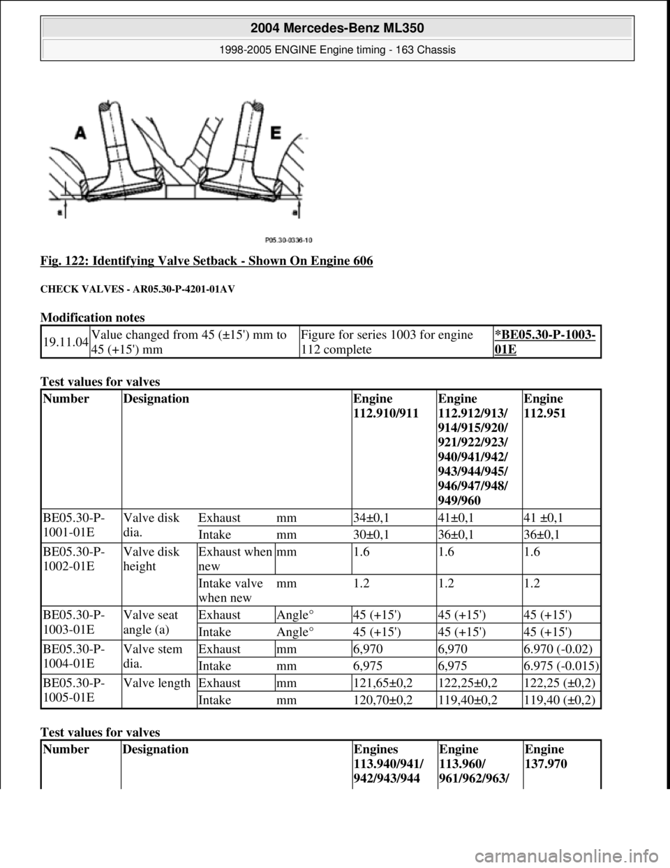
Fig. 122: Identifying Valve Setback - Shown On Engine 606
CHECK VALVES - AR05.30-P-4201-01AV
Modification notes
Test values for valves
Test values for valves
19.11.04Value changed from 45 (±15') mm to
45 (+15') mmFigure for series 1003 for engine
112 complete*BE05.30-P-1003-
01E
NumberDesignationEngine
112.910/911Engine
112.912/913/
914/915/920/
921/922/923/
940/941/942/
943/944/945/
946/947/948/
949/960Engine
112.951
BE05.30-P-
1001-01EValve disk
dia.Exhaustmm34±0,141±0,141 ±0,1
Intakemm30±0,136±0,136±0,1
BE05.30-P-
1002-01EValve disk
heightExhaust when
newmm1.61.61.6
Intake valve
when newmm1.21.21.2
BE05.30-P-
1003-01EValve seat
angle (a)ExhaustAngle°45 (+15')45 (+15')45 (+15')
IntakeAngle°45 (+15')45 (+15')45 (+15')
BE05.30-P-
1004-01EValve stem
dia.Exhaustmm6,9706,9706.970 (-0.02)
Intakemm6,9756,9756.975 (-0.015)
BE05.30-P-
1005-01EValve lengthExhaustmm121,65±0,2122,25±0,2122,25 (±0,2)
Intakemm120,70±0,2119,40±0,2119,40 (±0,2)
NumberDesignationEngines
113.940/941/
942/943/944Engine
113.960/
961/962/963/ Engine
137.970
2004 Mercedes-Benz ML350
1998-2005 ENGINE Engine timing - 163 Chassis
me
Saturday, October 02, 2010 3:39:39 PMPage 110 © 2006 Mitchell Repair Information Company, LLC.
Page 2352 of 4133
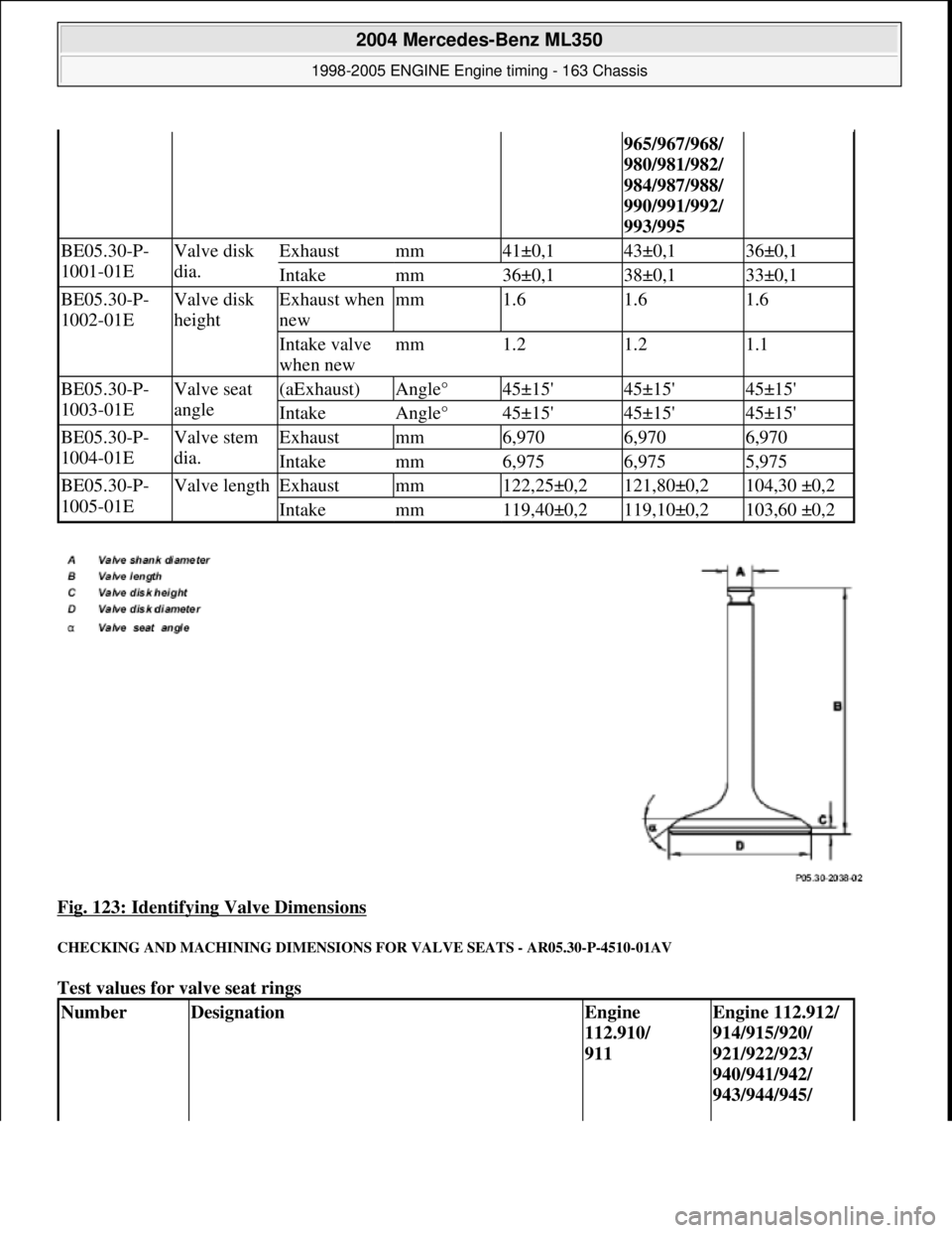
Fig. 123: Identifying Valve Dimensions
CHECKING AND MACHINING DIMENSIONS FOR VALVE SEATS - AR05.30-P-4510-01AV
Test values for valve seat rings
965/967/968/
980/981/982/
984/987/988/
990/991/992/
993/995
BE05.30-P-
1001-01EValve disk
dia.Exhaustmm41±0,143±0,136±0,1
Intakemm36±0,138±0,133±0,1
BE05.30-P-
1002-01EValve disk
heightExhaust when
newmm1.61.61.6
Intake valve
when newmm1.21.21.1
BE05.30-P-
1003-01EValve seat
angle(aExhaust)Angle°45±15'45±15'45±15'
IntakeAngle°45±15'45±15'45±15'
BE05.30-P-
1004-01EValve stem
dia.Exhaustmm6,9706,9706,970
Intakemm6,9756,9755,975
BE05.30-P-
1005-01EValve lengthExhaustmm122,25±0,2121,80±0,2104,30 ±0,2
Intakemm119,40±0,2119,10±0,2103,60 ±0,2
NumberDesignationEngine
112.910/
911Engine 112.912/
914/915/920/
921/922/923/
940/941/942/
943/944/945/
2004 Mercedes-Benz ML350
1998-2005 ENGINE Engine timing - 163 Chassis
me
Saturday, October 02, 2010 3:39:39 PMPage 111 © 2006 Mitchell Repair Information Company, LLC.