Page 1138 of 4133
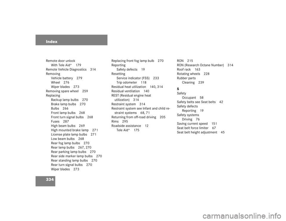
334 IndexRemote door unlock
With Tele Aid* 179
Remote Vehicle Diagnostics 314
Removing
Vehicle battery 279
Wheel 276
Wiper blades 273
Removing spare wheel 259
Replacing
Backup lamp bulbs 270
Brake lamp bulbs 270
Bulbs 266
Front lamp bulbs 268
Front turn signal bulbs 268
Fuses 287
High beam bulbs 269
High mounted brake lamp 271
License plate lamp bulbs 271
Low beam bulbs 268
Rear fog lamp bulbs 270
Rear lamp bulbs 267, 270
Rear parking lamp bulbs 270
Rear side marker lamp bulbs 270
Rear standing lamp bulbs 270
Rear turn signal bulbs 270
Wiper blades 273Replacing front fog lamp bulb 270
Reporting
Safety defects 19
Resetting
Service indicator (FSS) 233
Trip odometer 118
Residual heat utilization 140, 314
Residual ventilation 140
REST (Residual engine heat
utilization) 314
Restraint system 314
Restraint system see Infant and child re-
straint systems 68, 71
Returning from off-road driving 205
Rims 295
Roadside assistance 12
Tele Aid* 175RON 215
RON (Research Octane Number) 314
Roof rack 163
Rotating wheels 228
Rubber parts
Cleaning 239
S
Safety
Occupant 58
Safety belts see Seat belts 42
Safety defects
Reporting 19
Safety systems
Driving 76
Saving current speed 151
Seat belt force limiter 67
Seat belt height adjustment 45
Page 1139 of 4133
335 Index
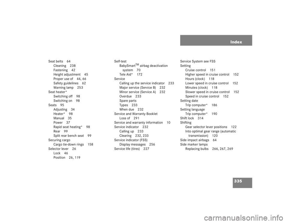
Seat belts 64
Cleaning 238
Fastening 42
Height adjustment 45
Proper use of 44, 66
Safety guidelines 62
Warning lamp 253
Seat heater*
Switching off 98
Switching on 98
Seats 95
Adjusting 34
Heater* 98
Manual 35
Power 37
Rapid seat heating* 98
Rear 99
Split rear bench seat 99
Securing cargo
Cargo tie-down rings 158
Selector lever 26
Lock 46
Position 26, 119Self-test
BabySmart
TM airbag deactivation
system 70
Tele Aid* 172
Service
Calling up the service indicator 233
Major service (Service B) 232
Minor service (Service A) 232
Overdue 233
Spare parts
Types 233
When due 232
Service and Warranty Booklet
Loss of 291
Service and warranty information 10
Service indicator 232
Calling up 233
Clearing 232, 233
Service indicator (FSS)
Display messages 256
Service life (tires) 227Service System see FSS
Setting
Cruise control 151
Higher speed in cruise control 152
Hours (clock) 118
Lower speed in cruise control 152
Minutes (clock) 118
Slower speed in cruise control 152
Speed in cruise control 152
Setting date
Trip computer* 186
Setting language
Trip computer* 190
Shift lock 314
Shifting
Gear selector lever positions 122
Into optimal gear range (automatic
transmission) 120
Side impact airbags 64
Side marker lamps
Replacing bulbs 266, 267, 269
Page 1140 of 4133
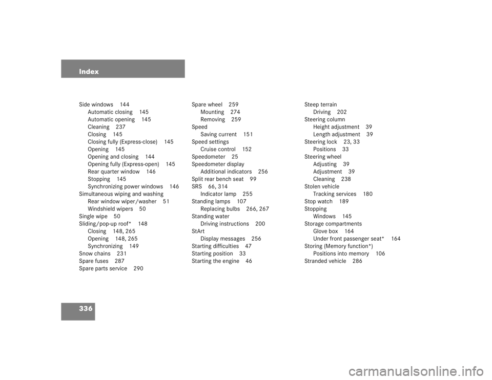
336 IndexSide windows 144
Automatic closing 145
Automatic opening 145
Cleaning 237
Closing 145
Closing fully (Express-close) 145
Opening 145
Opening and closing 144
Opening fully (Express-open) 145
Rear quarter window 146
Stopping 145
Synchronizing power windows 146
Simultaneous wiping and washing
Rear window wiper/washer 51
Windshield wipers 50
Single wipe 50
Sliding/pop-up roof* 148
Closing 148, 265
Opening 148, 265
Synchronizing 149
Snow chains 231
Spare fuses 287
Spare parts service 290Spare wheel 259
Mounting 274
Removing 259
Speed
Saving current 151
Speed settings
Cruise control 152
Speedometer 25
Speedometer display
Additional indicators 256
Split rear bench seat 99
SRS 66, 314
Indicator lamp 255
Standing lamps 107
Replacing bulbs 266, 267
Standing water
Driving instructions 200
StArt
Display messages 256
Starting difficulties 47
Starting position 33
Starting the engine 46Steep terrain
Driving 202
Steering column
Height adjustment 39
Length adjustment 39
Steering lock 23, 33
Positions 33
Steering wheel
Adjusting 39
Adjustment 39
Cleaning 238
Stolen vehicle
Tracking services 180
Stop watch 189
Stopping
Windows 145
Storage compartments
Glove box 164
Under front passenger seat* 164
Storing (Memory function*)
Positions into memory 106
Stranded vehicle 286
Page 1817 of 4133
Front seats
Seat belts/emergency tensioning retractors
MAINTENANCE
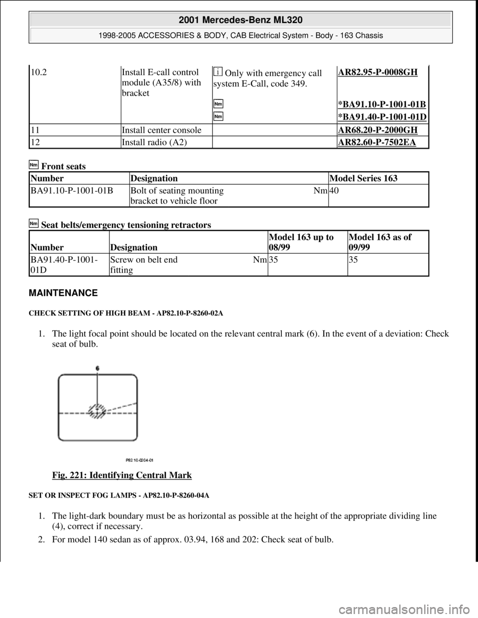
CHECK SETTING OF HIGH BEAM - AP82.10-P-8260-02A
1. The light focal point should be located on the relevant central mark (6). In the event of a deviation: Check
seat of bulb.
Fig. 221: Identifying Central Mark
SET OR INSPECT FOG LAMPS - AP82.10-P-8260-04A
1. The light-dark boundary must be as horizontal as possible at the height of the appropriate dividing line
(4), correct if necessary.
2. For model 140 sedan as of approx. 03.94, 168 and 202: Check seat of bulb.
10.2Install E-call control
module (A35/8) with
bracket Only with emergency call
system E-Call, code 349.AR82.95-P-0008GH
*BA91.10-P-1001-01B
*BA91.40-P-1001-01D
11Install center console AR68.20-P-2000GH
12Install radio (A2) AR82.60-P-7502EA
NumberDesignationModel Series 163
BA91.10-P-1001-01BBolt of seating mounting
bracket to vehicle floorNm40
NumberDesignation
Model 163 up to
08/99Model 163 as of
09/99
BA91.40-P-1001-
01DScrew on belt end
fittingNm3535
2001 Mercedes-Benz ML320
1998-2005 ACCESSORIES & BODY, CAB Electrical System - Body - 163 Chassis
me
Saturday, October 02, 2010 3:30:10 PMPage 322 © 2006 Mitchell Repair Information Company, LLC.
Page 1819 of 4133
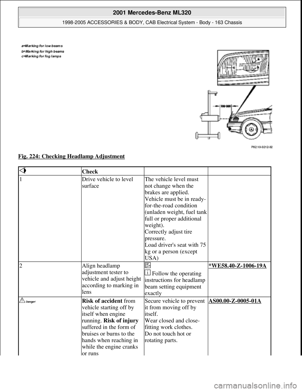
Fig. 224: Checking Headlamp Adjustment
Check
1Drive vehicle to level
surfaceThe vehicle level must
not change when the
brakes are applied.
Vehicle must be in ready-
for-the-road condition
(unladen weight, fuel tank
full or proper additional
weight).
Correctly adjust tire
pressure.
Load driver's seat with 75
kg or a person (except
USA)
2Align headlamp
adjustment tester to
vehicle and adjust height
according to marking in
lens
Follow the operating
instructions for headlamp
beam setting equipment
exactly*WE58.40-Z-1006-19A
Risk of accident from
vehicle starting off by
itself when engine
running. Risk of injury
suffered in the form of
bruises or burns to the
hands when reaching in
while the engine cranks
or runsSecure vehicle to prevent
it from moving off by
itself.
Wear closed and close-
fitting work clothes.
Do not touch hot or
rotating parts.AS00.00-Z-0005-01A
2001 Mercedes-Benz ML320
1998-2005 ACCESSORIES & BODY, CAB Electrical System - Body - 163 Chassis
me
Saturday, October 02, 2010 3:30:10 PMPage 324 © 2006 Mitchell Repair Information Company, LLC.
Page 1887 of 4133
material (8)
18Plug remaining antenna
cable of FM modulator
(9) into radio
19Install radio (A2)
Remove/install radio AR82.60-P-7502EA
20Retrofit video monitor (2)
and wiring harness of
video monitor (C) With glass version of
electric sliding/tilting
roof, code 414a.AZ82.60-P-0004-02A
Except glass version
of electric sliding/ tilting
roof, code 414a.AZ82.60-P-0004-02B
21Secure upper right B-
pillar paneling Ensure that the lugs of
the seat belt height
adjustment are located
correctly in the recess
clearance of the paneling.
22Install right front handle
23Install right sun visor
Remove/install sun visor AR68.60-P-5480GH
24Install right front A-pillar
cover
Remove/install paneling
on A-pillar AR68.30-P-4050GH
25Re-secure upper area of
rubber door seal
26Route wiring harness of
video/DVD player (B),
additional interface
module (4) and wiring
harness of video monitor
(C) later Up to VIN A289564,
X754619.AZ82.60-P-0004-03A
As of VIN A289565,
X754620.AZ82.60-P-0004-03B
27Retrofit auxiliary
interface module (4) in
center console Up to VIN A289564,
X754619.AZ82.60-P-0004-04A
As of VIN A289565,
X754620.AZ82.60-P-0004-04B
28Install center console
insulating mat
29Install center console
Remove/install center
console AR68.20-P-2000GH
2001 Mercedes-Benz ML320
1998-2005 ACCESSORIES & BODY, CAB Electrical System - Body - 163 Chassis
me
Saturday, October 02, 2010 3:30:12 PMPage 392 © 2006 Mitchell Repair Information Company, LLC.
Page 1893 of 4133
Fig. 315: Identifying Transfer Case Cont rol Module And CAN Bus Wiring Harness
7. Route connector (8) for TrafficStar wiring harness (4) from radio shaft along fan duct to center console.
Fig. 316: Identifying Trafficstar Wiring Harness And Connector
Steps 8-11 apply only for vehicl es with manual transmission
8. Separate green lead (gn) from CAN bus ad apter connector (8) (see magnifying glass).
9. Tie TrafficStar (4) wiring harn ess on at height of shift gate and pull out green lead (gn).
Fig. 317: Identifying CAN Bus Adapter Conn ector And Trafficstar Wiring Harness
10. Route green lead (gn) to bac
k-up lamp switch (S16/2).
2001 Mercedes-Benz ML320
1998-2005 ACCESSORIES & BODY, CAB Electr ical System - Body - 163 Chassis
me
Saturday, October 02, 2010 3:30:12 PMPage 398 © 2006 Mitchell Repair Information Company, LLC.
Page 1899 of 4133
8. Separate green lead (gn) from CAN bus adapter connector (8).
9. Tie TrafficStar (4) wiring harness on at height of shift gate and pull out green lead (gn).
Fig. 329: Identifying CAN Bus Adapter Connector And Trafficstar Wiring Harness
10. Route green lead (gn) to back-up lamp switch (S16/2).
11. Connect lower gray lead (gr) from connector with assignment 2 for back-up lamp switch (S16/2) to green
lead (gn) using solder connector.
The connector for the back-up lamp switch (S16/2) has two gray leads, the lower of the two leads is
for the switched back-up lamp signal.
Fig. 330: Identifying Back
-Up Lamp Switch And Green Lead
12. Connect connector (8) and lead (6) to CAN bus adapter (5).
13. Install center console.
2001 Mercedes-Benz ML320
1998-2005 ACCESSORIES & BODY, CAB Electrical System - Body - 163 Chassis
me
Saturday, October 02, 2010 3:30:12 PMPage 404 © 2006 Mitchell Repair Information Company, LLC.