1997 MERCEDES-BENZ ML350 light
[x] Cancel search: lightPage 2032 of 4133
AR09.41-P-6817MM
Removing and installing charge air cooler
10.11.99
ENGINE
612.963 in MODEL 163.113
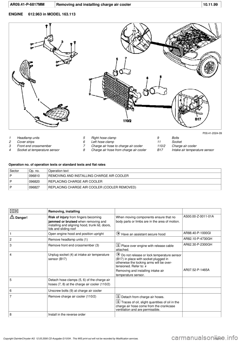
P09.41-2024-09
1
Headlamp units
2
Cover strips
3
Front end crossmember
4
Socket at temperature sensor
9
Bolts
11
Socket
110/2
Charge air cooler
B17
Intake air temperature sensor
5
Right hose clamp
6
Left hose clamp
7
Charge air hose to charge air cooler
8
Charge air hose from charge air cooler
Operation no. of operation texts or standard texts and flat rates
Sector
Op. no.
Operation text
P
096810
REMOVING AND INSTALLING CHARGE AIR COOLER
P
096820
REPLACING CHARGE AIR COOLER
P
096827
REPLACING CHARGE AIR COOLER (COOLER REMOVED)
Removing, installing
Danger!
Risk of injury
from fingers becoming
jammed or bruised
when removing and
installing and aligning hood, trunk lid, doors,
lids and sliding roof
When moving components ensure that no
body parts or limbs are in the area of motion.
AS00.00-Z-0011-01A
1
Open engine hood and position upright
Have an assistant secure hood
AR88.40-P-1000GI
2
Remove headlamp units (1)
AR82.10-P-4730GH
3
Remove front end crossmember (3)
Place over engine with release cable
attached.
AR62.30-P-2300GH
4
Unplug socket (4) at intake air temperature
sensor (B17)
Do not release or lock temperature sensor
(B17) in place with socket plugged in
otherwise the locking arms will be over-
tensioned. Refer to:
#
Removing and installing intake air
temperature sensor.
AR07.52-P-1465A
5
Detach hose clamps (5, 6) of the charge air
hoses (7, 8) at the charge air cooler (110/2)
6
Unscrew bolts (9) at charge air cooler
7
Remove charge air cooler (110/2)
Detach from charge air hoses.
Traces of oil, slight quantities of oil in the
charge air hose come from the crankcase
ventilation and are permissible.
8
Install in the reverse order
Copyright DaimlerChrysler AG 12.05.2006 CD-Ausgabe G/10/04 . This WIS print-out will not be recorde
d by Modification services.
Page 1
Page 2048 of 4133
Fig. 8: Connecting Hand Held Tester Scan Tool To OBD-II Data Link Connector
Courtesy of MERCEDES-BENZ OF NORTH AMERICA.
ON-VEHICLE TESTING
WIRING CONTINUITY
1. Connect voltmeter between generator B+ terminal and ground. Voltmeter should indicate battery voltage.
If battery voltage is not indicated, check battery and check wiring between generator and battery for
corrosion, loose terminals, etc.
2. Turn ignition on and ensure instrument cluster charge indicator light (battery symbol) comes on. If light
does not come on, check wiring between generator and warning light, including indicator bulb.
GENERATOR OUTPUT
1. Ensure connections at battery and generator are clean and tight. Ensure generator, engine and body are
properly grounded. Ensure generator drive belt is properly adjusted and in good condition.
2. Connect load tester/ammeter as per tester manufacturer's instructions. Connect voltmeter leads to battery
terminals. See Fig. 9
. Start engine and run at 2200 RPM for V6 or 2500 RPM for V8. Adjust load tester
to obtain maximum generator output. DO NOT allow voltage to drop to less than 12.7 volts.
3. Maximum generator output should be within a few amps of generator rated output stamped on generator.
If output is not within a few amps of generator rated output, check generator diodes. See DIODE TEST
.
Replace
generator as necessary.
2001 Mercedes-Benz ML320
2001-04 STARTING & CHARGING SYSTEMS Generators & Regulators - 163 Chassis
me
Saturday, October 02, 2010 3:20:32 PMPage 14 © 2006 Mitchell Repair Information Company, LLC.
Page 2050 of 4133
VOLTAGE REGULATOR CONTROL
1. Connect multimeter. See Fig. 10 . Ensure charge indicator light goes out when engine is idling and with
increasing engine speed up to 3000 RPM. Apply load to battery by turning on headlights and noting
reading after 2 minutes.
2. Voltage reading should be 13-14.5 volts. If voltage is not to specification, replace voltage regulator. See
VOLTAGE REGULATOR
under REMOVAL & INSTALLATION. If regulator is okay, replace
generator. See GENERATOR under REMOVAL & INSTALLATION.
2001 Mercedes-Benz ML320
2001-04 STARTING & CHARGING SYSTEMS Generators & Regulators - 163 Chassis
me
Saturday, October 02, 2010 3:20:32 PMPage 16 © 2006 Mitchell Repair Information Company, LLC.
Page 2080 of 4133
Crankshaft Position Sensor DIY
hopefully this will help others with what appears to be a common stalling issue in the ML series.
Location:
--------
It's on the rear of the engine where the engine mates with the tranny on the driver's side. There are 2
types. Be sure to get the correct one
Here it is:
1) Get
CPS
at dealer, its a VIN specific part. $125 from my local stealer.
2) Tools needed: Socket screwdriver, Good lighting (portable) shop lights, size 8 outside torx socket,
maybe a ratche
t and extentions depending on your flexibility, magnetic part retrieval tool (skip this at
your peril), bath towel, and long sleeve shirt, step stool, blue thread locker (optional)
3) Open hood and remove engine cover, it just pulls off and on
4) Set wor
k light(s) toward back of engine, lighting behind drivers cylinder head
5) Set bath towel on front of ML to kneel on of your knees will die, wearing long sleeve shirt or your
wrists will be cut.
6) Climb up on towel and look behind engine from above and
right (see .jpg), finding torx attachment
holding your
CPS
.
7) Remove torx screw and pull out
CPS
, disconnect one way connector (wiring)
8) Replace with new (leaving wire detached for now)
9) This is the hardest step by far, and requires patience and fl exibility. Apply some thread locker and
insert screw and start the threads. Tighten with torx on socket screwdriver. This step took about 1/2
hour and numerous dropped screws and retrievals with mag tool.
10) Attach wiring to
CPS
11) Reinstall engine cov
er
12) Clean up tools, towel and lights and everything
13) Drink beer and toast yourself for saving yourself at least $100 and a day of your time dropping off
and picking up cars at shop
Hope this helps someone in the community.
Dickie
00 ML 32
0
Page 2082 of 4133

Remove/Install
1.1
Remove engine compartment cover with
integrated air cleaner
All except Engine 112.960 in Model 170.466,
Engine 112.961 in Model 203.065/ 265
Remove air cleaner by lifting vertically up
and away from the cylinder head covers.
Installation:
With sliding compound,
slightly moisten the rubber retainers on the
cylinder head covers and the sealing ring of
the hot film mass air flow sensor in the air
cleaner housing.
1.2
Remove air cleaner housing
Engine 112.960 in Model 170.466
Engine 112.961 in Model 203.065/265
AR09.10-P-1150SVK
2
Remove crankshaft position sensor (L5)
*BA15.10-P-1001-03A
3
Install in the reverse order
4.1
Reinitialize crankshaft position sensor (L5)
using STAR DIAGNOSIS
If the crankshaft position sensor (L5) was
replaced, a re-initialization must be carried
out with STAR DIAGNOSIS in the "Control
unit adaptations" menu item.
Diagnosis system STAR DIAGNOSIS
*WE58.40-Z-1013-06A
Position sensor
Number
Designation
Engine
112.910/911/912/
913/914/915/
916/917/920/
921/922/923/
940/941/942/
943/944/945/
946/947/949/
951/953/954/
955/960/961/
970/972/973/975
Engine
113.940/941/
942/943/944/
948/960/961/
962/963/965/
966/967/968/
969/980/981/
982/984/986/
992/993
BA15.10-P-1001-03A
Crankshaft position sensor to engine block
Nm
88
Workshop equipment/MB testers
(see Workshop Equipment Manual)
WE58.40-Z-1013-06A
Compact STAR DIAGNOSIS system for passenger cars, order number 6511 1801 00
Copyright DaimlerChrysler AG 29.05.2006 CD-Ausgabe G/10/04 . This WIS print-out will not be recorde
d by Modification services.
Page 2
Page 2106 of 4133

AD54.30-P-3000-03A
Display instruments/multi-function display
function check IC
Display
instruments
The display instruments must indicate according to operating
conditions.
Phototransistor (models 202, 208, 210)
Point a beam of light at the phototransistor with a pocket lamp, the
display illumination of the LCD displays (outside temperature, trip
odometer, total mileage recorder and electronic clock) must get
brighter.
Instrument cluster with multi-function display
If there are malfunctions (e.g. brake linings worn, coolant level too
low, exterior lamp failure etc.) or system faults (anti-lock brake
system faulty, supplemental restraint system faulty) the warning
display with warning information is inserted in place of outside
temperature, odometer, total mileage recorder and electronic clock.
The warning information is displayed in yellow or red depending on
the fault and a warning tone also sounds.
Copyright DaimlerChrysler AG 05.06.2006 CD-Ausgabe G/10/04 . This WIS print-out will not be recorde
d by Modification services.
Page 1
Page 2120 of 4133
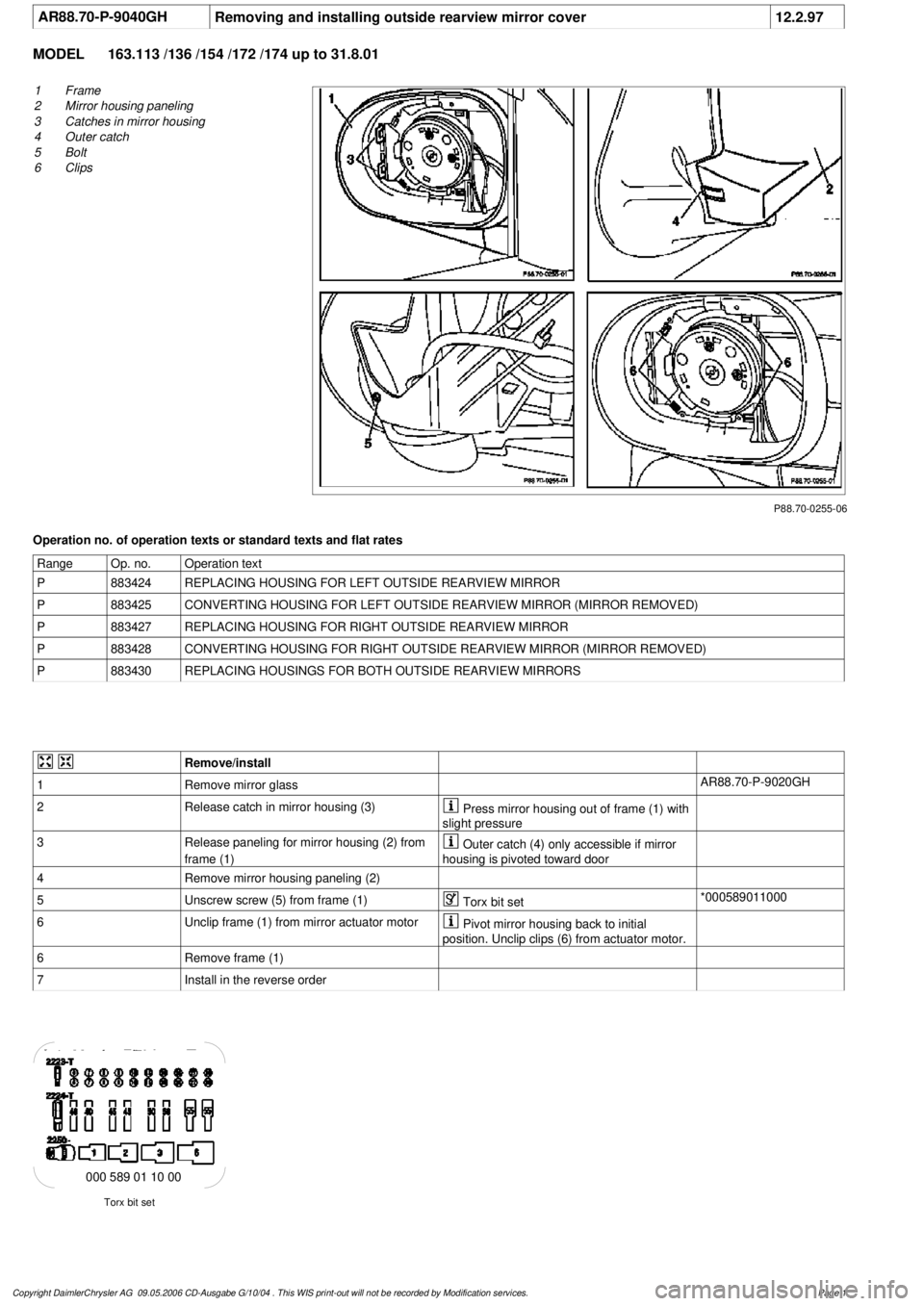
AR88.70-P-9040GH
Removing and installing outside rearview mirror cover
12.2.97
MODEL
163.113 /136 /154 /172 /174 up to 31.8.01
P88.70-0255-06
1
Frame
2
Mirror housing paneling
3
Catches in mirror housing
4
Outer catch
5
Bolt
6
Clips
Operation no. of operation texts or standard texts and flat rates
Range
Op. no.
Operation text
P
883424
REPLACING HOUSING FOR LEFT OUTSIDE REARVIEW MIRROR
P
883425
CONVERTING HOUSING FOR LEFT OUTSIDE REARVIEW MIRROR (MIRROR REMOVED)
P
883427
REPLACING HOUSING FOR RIGHT OUTSIDE REARVIEW MIRROR
P
883428
CONVERTING HOUSING FOR RIGHT OUTSIDE REARVIEW MIRROR (MIRROR REMOVED)
P
883430
REPLACING HOUSINGS FOR BOTH OUTSIDE REARVIEW MIRRORS
Remove/install
1
Remove mirror glass
AR88.70-P-9020GH
2
Release catch in mirror housing (3)
Press mirror housing out of frame (1) with
slight pressure
3
Release paneling for mirror housing (2) from
frame (1)
Outer catch (4) only accessible if mirror
housing is pivoted toward door
4
Remove mirror housing paneling (2)
5
Unscrew screw (5) from frame (1)
Torx bit set
*000589011000
6
Unclip frame (1) from mirror actuator motor
Pivot mirror housing back to initial
position. Unclip clips (6) from actuator motor.
6
Remove frame (1)
7
Install in the reverse order
Torx bit set
000 589 01 10 00
Copyright DaimlerChrysler AG 09.05.2006 CD-Ausgabe G/10/04 . This WIS print-out will not be recorde
d by Modification services.
Page 1
Page 2139 of 4133

GF54.21-P-4106-01GH
Extended Activity Module - Task
n
The primary tasks of the Extended Activity Module (EAM, N10/1) are
as follows:
D
To control the door sill lights
D
To suppress the auto-dimming mirror function
D
To control the headlight cleaning system (HCS)
D
To control the rear window defroster
D
To control seat heating
D
To control the power supply via control console to tilt/sliding or
louvered sunroof switch
D
To control the PTC heater booster (R22/3)
D
To control the auxiliary fan (M4)
D
To read the cruise control switch (S40) and relay data to control
module (DAS, N73/1)
D
To read the contacts for wiper speed settings 1 and 2 on
combination switch (S4) for diagnosis.
To perform these tasks the Extended Activity Module (EAM, N10/1)
reads various signals and switch settings directly.
The Extended Activity Module (EAM, N10/1) interfaces with other
control modules via the engine compartment CAN.
-----------------------------------------------------------------------------------------
Diagnosis
Diagnosis is performed using the Star diagnostic tool. To facilitate
this task, the Extended Activity Module (EAM, N10/1) is equipped
with its own diagnostics cable.
This cable is also used to diagnose the
All Activity Module (AAM,
N10)
and the
transfer case control module (N78)
.
The Extended Activity Module (EAM, N10/1) is linked to the All
Activity Module (AAM, N10) via the
engine compartment CAN
.
Data communication between the All Activity Module (AAM,
N10) and the Extended Activity Module (EAM, N10/1) is
assumed by the
CAN (N10 - N10/1)
when terminal 15 is off.
The CAN (N10 - N10/1)
is an independent CAN bus located
between the All Activity Module (AAM, N10) and the Extended
Activity Module (EAM, N10/1).
No other
control modules are
connected to the CAN (N10 - N10/1).
-----------------------------------------------------------------------------------------
Details:
Door sill lights
When the front interior light is on and one of the front doors is open,
or when the rear interior light is on and one of the back doors is open,
the door sill lights for the open door will illuminate.
Headlight cleaning system (HCS)
Activating a separate switch causes the EAM to send a turn-on signal
to the HCS pump relay.
EAM will send an additional turn-on signal to the HCS pump relay
only after the cleaning operation is completed and a "rest period" of
approximately 2.5 sec. has passed.
Auto-dimming mirror function
The auto-dimming mirror function is suppressed when the interior
light is on or reverse gear is engaged.
Auto-dimming suppression for the outside rearview mirror (slave) is
activated by the inside rearview mirror (master).
Heater booster/PTC air heater for diesel engines
EAM monitors system voltage and adjusts heater booster capacity to
minimize load on battery.
Rear window defroster
EAM sets maximum ON time for rear window defroster depending
on outdoor temperature and current vehicle speed.
D
Standard ON time:
10 min.
D
Outdoor temperature < 5
o
C:
Additional 5 min.
D
Speed >80 km/h:
Additional 3 min.
Seat heating
Sets maximum seat heating time.
D
Setting 1: max. 20 min.
D
Setting 2: max. 5 min.
Tilt/sliding or louvered sunroofs
Signal via AAM2 allows operation of tilt/sliding or louvered sunroofs
when ignition is on (standard mode) or off (keyless mode).
Ignition authorization via CAN
The EAM issues ignition authorization to AAM2 via the engine
compartment CAN depending on the requirements of the engine
control unit in connection with the FBM.
Copyright DaimlerChrysler AG 18.05.2006 CD-Ausgabe G/10/04 . This WIS print-out will not be recorde
d by Modification services.
Page 1