Page 2428 of 4133
8. Hold jacket sleeve (5)
9. Rotate screw-in spindle (6) until the stop ring (7) is pos itioned on the jacket sleeve (5). Slightly turn back
a clamping jacket sleeve when screwing-in.
Fig. 65: Identifying Jacket Sleeve, Spindle And Stop Ring
10. Insert sleeve (9) via primary pum p drive of HELI-COIL insert
11. Guide open pliers to the marking in the sleeve (9) and fix with primary pump drive
12. Close pliers , the serrated lock of pliers must latch.
13. Rotate sleeve (9) toward left as far as the stop and hold
14. Dismount primary pump drive, to do so move pliers slightly up and down.
Remove with a ma
gnet the primary pump drive which had fallen onto the piston crown!
2001 Mercedes-Benz ML320
1998-2005 ENGINE Complete engine - 163 Chassis
me
Saturday, October 02, 2010 3:17:56 PMPage 72 © 2006 Mitchell Repair Information Company, LLC.
Page 2487 of 4133
Fig. 106: Identifying Oil Pan Remove/Install Components - Shown On Engine 112
Remove/install
External torx setFig. 49
1Remove oil pan bottom
section (1)Model 163.154/157/172.AR01.45-P-7555V
Model 163.174/175.AR01.45-P-7555VE
*BA01.45-P-1002-01B
2Disconnect electrical line
at oil sensor (oil level,
temperature and quality)
(B40) Remove cable strap at oil
pipe.
3Remove oil pipe (2) from
dipstick Installation: Replace the
sealing ring!AR18.40-P-3510BV
*BA01.20-P-1001-01E
4Remove oil pan top
section(3)Take out oil pan to the front in
direction of travel for this step;
rotate crankshaft slightly, if
necessary.
Installation: Observe
different bolt length and bolt
diameter: ?
Screw diagram of oil panAR01.45-P-7500-06F
Notes on application of
sealant to oil panEngine 112AH01.45-P-0001-01C
2001 Mercedes-Benz ML320
1998-2005 ENGINE Complete engine - 163 Chassis
me
Saturday, October 02, 2010 3:17:58 PMPage 131 © 2006 Mitchell Repair Information Company, LLC.
Page 2514 of 4133
AP82.10-P-8260-04A
Set or inspect fog lamps
P82.10-0205-01
1
The light-dark boundary must be as horizontal as possible at the height of the appropriate
dividing line (4), correct if necessary.
2
For model 140 sedan as of approx. 03.94, 168 and 202: Check seat of bulb.
P82.10-3633-01
Model 163.113 /154 #A as of 289565,
163.113 #X as of 754620,
163.128 /154 /157 /175 except CODE (U49) Styling package
Arrow:
Position of adjusting screw
Copyright DaimlerChrysler AG 20.05.2006 CD-Ausgabe G/10/04 . This WIS print-out will not be recorde
d by Modification services.
Page 1
Page 2516 of 4133
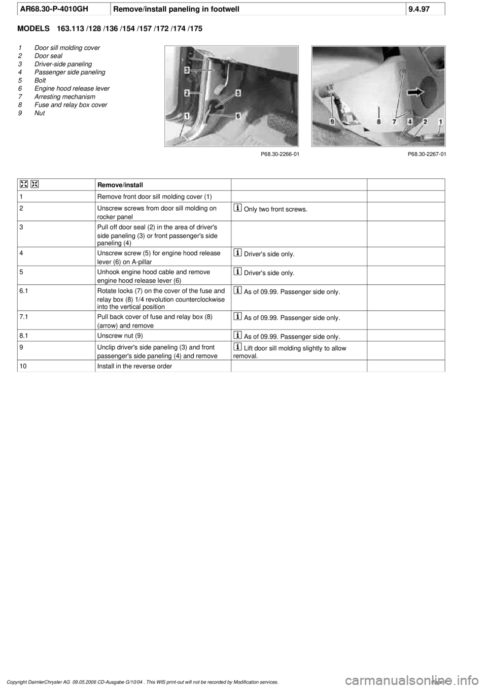
AR68.30-P-4010GHRemove/install paneling in footwell
9.4.97
MODELS
163.113 /128 /136 /154 /157 /172 /174 /175
P68.30-2266-01
1
Door sill molding cover
2
Door seal
3
Driver-side paneling
4
Passenger side paneling
5
Bolt
6
Engine hood release lever
7
Arresting mechanism
8
Fuse and relay box cover
9
Nut
P68.30-2267-01
Remove/install
1
Remove front door sill molding cover (1)
2
Unscrew screws from door sill molding on
rocker panel
Only two front screws.
3
Pull off door seal (2) in the area of driver's
side paneling (3) or front passenger's side
paneling (4)
4
Unscrew screw (5) for engine hood release
lever (6) on A-pillar
Driver's side only.
5
Unhook engine hood cable and remove
engine hood release lever (6)
Driver's side only.
6.1
Rotate locks (7) on the cover of the fuse and
relay box (8) 1/4 revolution counterclockwise
into the vertical position
As of 09.99. Passenger side only.
7.1
Pull back cover of fuse and relay box (8)
(arrow) and remove
As of 09.99. Passenger side only.
8.1
Unscrew nut (9)
As of 09.99. Passenger side only.
9
Unclip driver's side paneling (3) and front
passenger's side paneling (4) and remove
Lift door sill molding slightly to allow
removal.
10
Install in the reverse order
Copyright DaimlerChrysler AG 09.05.2006 CD-Ausgabe G/10/04 . This WIS print-out will not be recorde
d by Modification services.
Page 1
Page 2524 of 4133
brake hoses *BA42.10-P-1001-04A
Ring wrench socketFig. 5
5Unbolt propeller shaft at
flange on front axle
transmission *BA41.20-P-1001-01A
6Remove left and right
front springs AR32.20-P-0200GH
7.1Remove lower engine
compartment panelingModel
163.157 /172 /174 /175AR61.20-P-1105GH
Model 163.113/ 128AR94.30-P-5400GH
8Detach torsion bar (28) at
vehicle frame *BA32.20-P-1001-02G
9Detach upper transverse
control arm (6) from
vehicle frame Installation: Tighten
new nuts slightly. Tighten
bolt fully only when
vehicle is on its wheels and
ready to drive.
*BA33.20-P-1006-01D
10Detach bracket for oil
lines from transmission to
oil cooler on front axle
carrier
11Unclip brake line at rear
of front-axle
crossmember
12.1Remove vehicle level
controller connecting rod
(95b) at lower transverse
control arm on right Vehicles with xenon
headlamps.
13Extract fluid from power
steering pump reservoir Hand pumpFig. 6
14Turn steering wheel to
center position (front
wheels in straight-ahead
position) and secureThe steering wheel must
not be turned when the
steering coupling has been
removed. This will damage
the fanfare horns and airbag
clock spring contact
beyond repair.
Remove ignition key
and turn steering wheel so
that it locks.
15.1Detach plug-in connector
for speed-sensitive power
steering to timing case Vehicles with speed-
sensitive power steering
only.
2001 Mercedes-Benz ML320
1998-2005 DRIVELINE/AXLES Front Axle - 163 Chassis
me
Saturday, October 02, 2010 3:38:21 PMPage 5 © 2006 Mitchell Repair Information Company, LLC.
Page 2533 of 4133
Box wrench bitFig. 5
8Detach track rod (10)
from steering knuckleCheck rubber boot and
ball joint for wear and
damage.AR46.40-P-0200-02C
*BA46.40-P-1001-01C
Thrust pieceFig. 16
PullerFig. 17
9.1Detach link rod of level
controller (95b) from
lower transverse control
arm on right-hand side Vehicles with xenon
headlamps.
10Detach upper transverse
control arm (6) from
vehicle frame Installation: Tighten
new nuts slightly until
they touch.
Only tighten the bolt
when the vehicle is on its
wheels in ready-to-drive
condition.
*BA33.20-P-1006-01D
11Press front axle shaft out
of front axle shaft flange AR33.30-P-0620-04GH
Removal and
installation toolFig. 18
12Support front axle half at
lower transverse control
arm with inspection pit or
assembly lift
13Detach torsion bar (28)
from lower transverse
control arm *BA32.20-P-1002-02G
14Detach lower transverse
control arm (4) from front
axle carrieri004 Installation:
Tighten new nuts slightly
until they touch.
Only tighten the bolt
when the vehicle is on its
wheels in ready-to-drive
condition.
*BA33.20-P-1004-01D
15Loosen clamped joint at
rear of lower transverse
control arm (4) and fold
down bearing shell (4d) Installation: Tighten
new nuts slightly until
they touch.
Only tighten the bolt
when the vehicle is on its
wheels in ready-to-drive
condition.
2001 Mercedes-Benz ML320
1998-2005 DRIVELINE/AXLES Front Axle - 163 Chassis
me
Saturday, October 02, 2010 3:38:22 PMPage 14 © 2006 Mitchell Repair Information Company, LLC.
Page 2553 of 4133
Front axle torsion strut
Wheel location, hub
REPLACE FRONT BEARING OF LOWER WISHBONE - AR33.20-P-0526GH
MODEL 163.113 /128 /136 /154 /157 /172 /174 /175
3.1
Remove linkage rod for suspension-
control module (95b) from lower
right control arm
Vehicles with xenon headlamps.
4Detach torsion bar (28) from lower
control arm *BA32.20-P-
1002-02G
5Detach lower control arm (4) from
front subframe
Installation: Tighten new nuts slightly.
Tighten bolt fully only when vehicle is on
its wheels and ready to drive.
*BA33.20-P-
1004-01D
6
Loosen clamped joint at rear of
lower wishbone (4) and fold down
bearing shell (4d)
Installation: Tighten new nuts slightly.
Tighten bolt fully only when vehicle is on
its wheels and ready to drive.
*BA33.20-P-
1005-01D
Inspect
7Inspect lower control arm for signs
of distortion and corrosion
8Install in the reverse order
9Perform chassis alignment check AR40.20-P-
0200GH
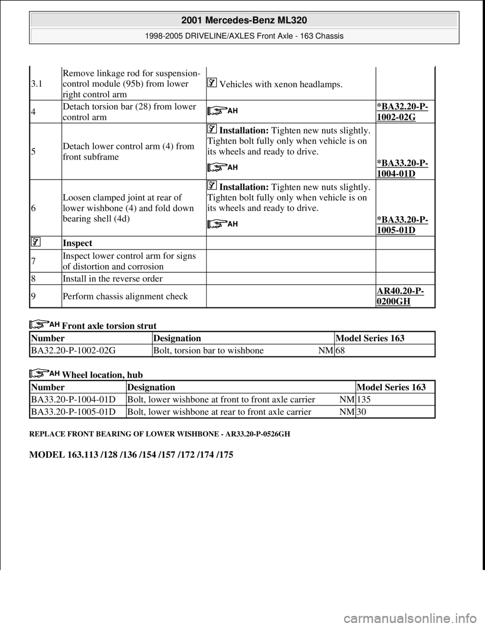
NumberDesignationModel Series 163
BA32.20-P-1002-02GBolt, torsion bar to wishboneNM68
NumberDesignationModel Series 163
BA33.20-P-1004-01DBolt, lower wishbone at front to front axle carrierNM135
BA33.20-P-1005-01DBolt, lower wishbone at rear to front axle carrierNM30
2001 Mercedes-Benz ML320
1998-2005 DRIVELINE/AXLES Front Axle - 163 Chassis
me
Saturday, October 02, 2010 3:38:22 PMPage 34 © 2006 Mitchell Repair Information Company, LLC.
Page 2591 of 4133
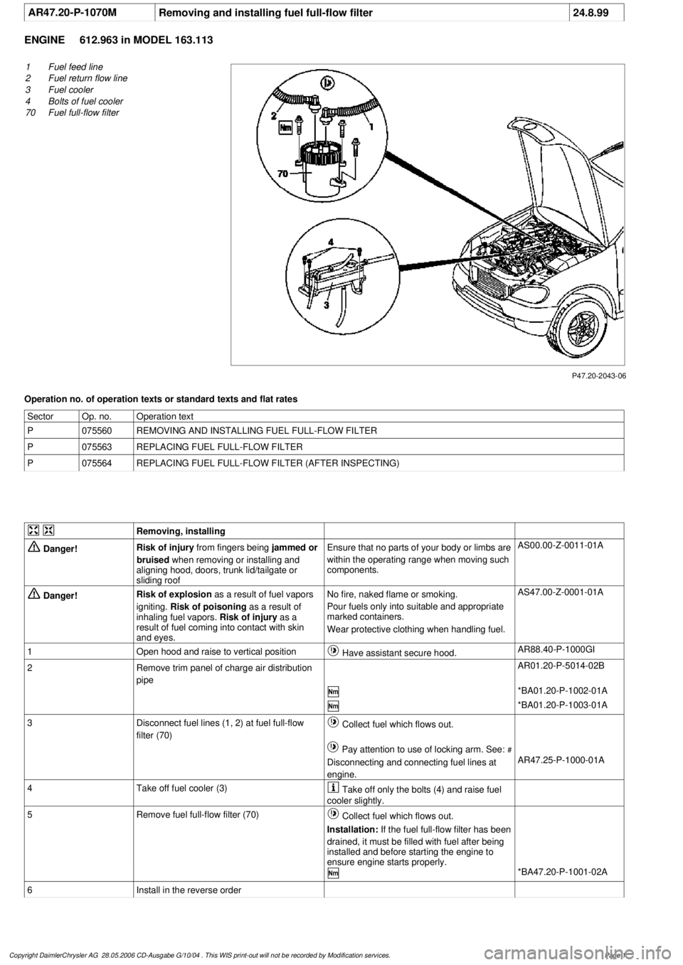
AR47.20-P-1070M
Removing and installing fuel full-flow filter
24.8.99
ENGINE
612.963 in MODEL 163.113
P47.20-2043-06
1
Fuel feed line
2
Fuel return flow line
3
Fuel cooler
4
Bolts of fuel cooler
70
Fuel full-flow filter
Operation no. of operation texts or standard texts and flat rates
Sector
Op. no.
Operation text
P
075560
REMOVING AND INSTALLING FUEL FULL-FLOW FILTER
P
075563
REPLACING FUEL FULL-FLOW FILTER
P
075564
REPLACING FUEL FULL-FLOW FILTER (AFTER INSPECTING)
Removing, installing
Danger!
Risk of injury
from fingers being
jammed or
bruised
when removing or installing and
aligning hood, doors, trunk lid/tailgate or
sliding roof
Ensure that no parts of your body or limbs are
within the operating range when moving such
components.
AS00.00-Z-0011-01A
Danger!
Risk of explosion
as a result of fuel vapors
igniting.
Risk of poisoning
as a result of
inhaling fuel vapors.
Risk of injury
as a
result of fuel coming into contact with skin
and eyes.
No fire, naked flame or smoking.
Pour fuels only into suitable and appropriate
marked containers.
Wear protective clothing when handling fuel.
AS47.00-Z-0001-01A
1
Open hood and raise to vertical position
Have assistant secure hood.
AR88.40-P-1000GI
2
Remove trim panel of charge air distribution
pipe
AR01.20-P-5014-02B
*BA01.20-P-1002-01A
*BA01.20-P-1003-01A
3
Disconnect fuel lines (1, 2) at fuel full-flow
filter (70)
Collect fuel which flows out.
Pay attention to use of locking arm. See:
#
Disconnecting and connecting fuel lines at
engine.
AR47.25-P-1000-01A
4
Take off fuel cooler (3)
Take off only the bolts (4) and raise fuel
cooler slightly.
5
Remove fuel full-flow filter (70)
Collect fuel which flows out.
Installation:
If the fuel full-flow filter has been
drained, it must be filled with fuel after being
installed and before starting the engine to
ensure engine starts properly.
*BA47.20-P-1001-02A
6
Install in the reverse order
Copyright DaimlerChrysler AG 28.05.2006 CD-Ausgabe G/10/04 . This WIS print-out will not be recorde
d by Modification services.
Page 1