1997 MERCEDES-BENZ ML350 light
[x] Cancel search: lightPage 2152 of 4133
COMPONENT LOCATION GRAPHICS
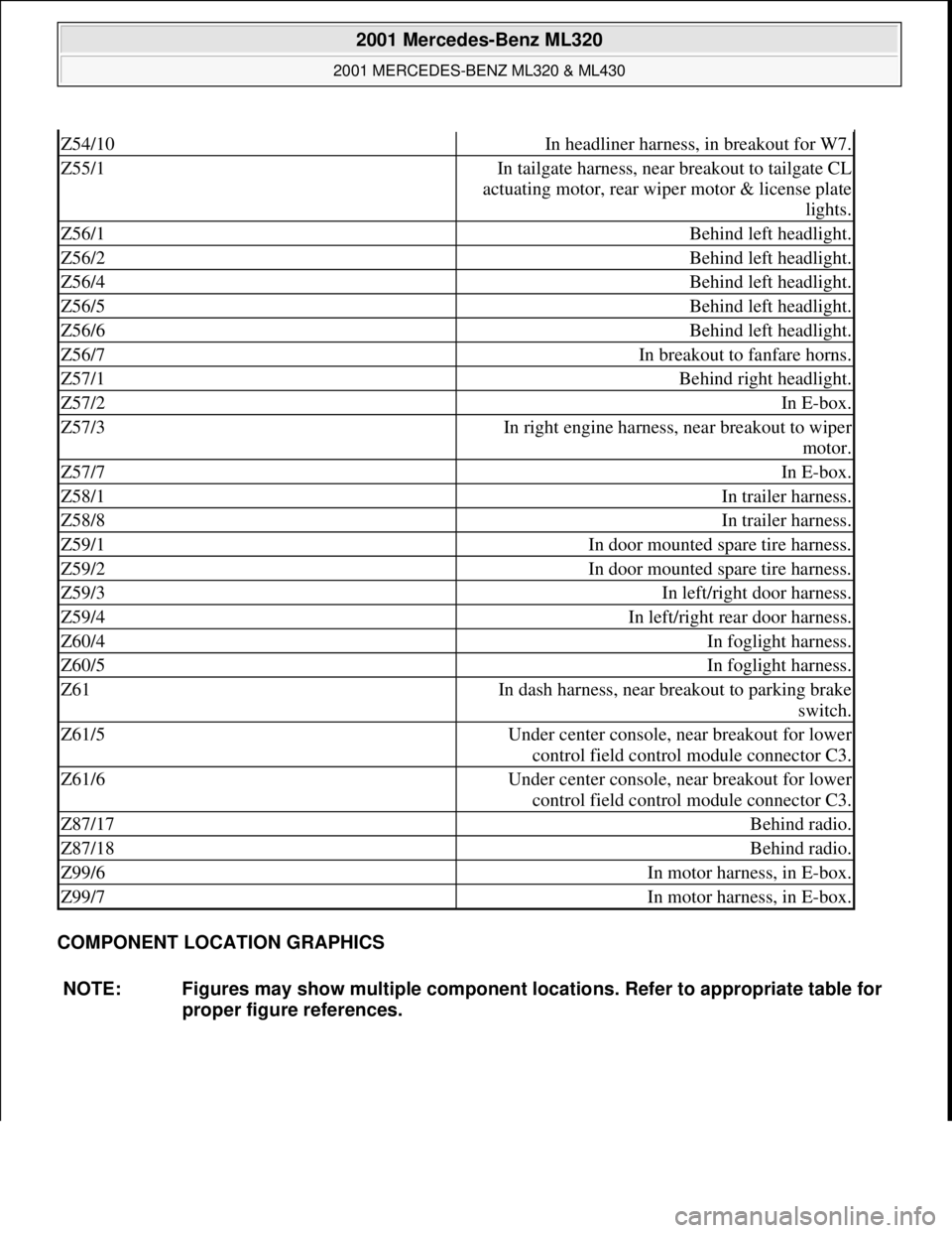
Z54/10In headliner harness, in breakout for W7.
Z55/1In tailgate harness, near breakout to tailgate CL
actuating motor, rear wiper motor & license plate
lights.
Z56/1Behind left headlight.
Z56/2Behind left headlight.
Z56/4Behind left headlight.
Z56/5Behind left headlight.
Z56/6Behind left headlight.
Z56/7In breakout to fanfare horns.
Z57/1Behind right headlight.
Z57/2In E-box.
Z57/3In right engine harness, near breakout to wiper
motor.
Z57/7In E-box.
Z58/1In trailer harness.
Z58/8In trailer harness.
Z59/1In door mounted spare tire harness.
Z59/2In door mounted spare tire harness.
Z59/3In left/right door harness.
Z59/4In left/right rear door harness.
Z60/4In foglight harness.
Z60/5In foglight harness.
Z61In dash harness, near breakout to parking brake
switch.
Z61/5Under center console, near breakout for lower
control field control module connector C3.
Z61/6Under center console, near breakout for lower
control field control module connector C3.
Z87/17Behind radio.
Z87/18Behind radio.
Z99/6In motor harness, in E-box.
Z99/7In motor harness, in E-box.
NOTE: Figures may show multiple component locations. Refer to appropriate table for
proper figure references.
2001 Mercedes-Benz ML320
2001 MERCEDES-BENZ ML320 & ML430
me
Saturday, October 02, 2010 3:21:17 PMPage 12 © 2006 Mitchell Repair Information Company, LLC.
Page 2185 of 4133
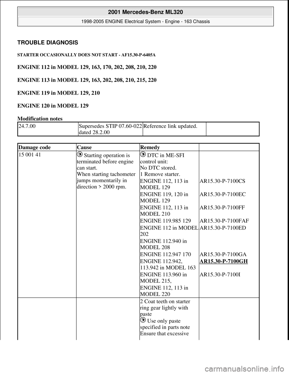
TROUBLE DIAGNOSIS
STARTER OCCASIONALLY DOES NOT START - AF15.30-P-6405A
ENGINE 112 in MODEL 129, 163, 170, 202, 208, 210, 220
ENGINE 113 in MODEL 129, 163, 202, 208, 210, 215, 220
ENGINE 119 in MODEL 129, 210
ENGINE 120 in MODEL 129
Modification notes
24.7.00Supersedes STIP 07.60-022
dated 28.2.00Reference link updated.
Damage codeCauseRemedy
15 001 41 Starting operation is
terminated before engine
can start.
When starting tachometer
jumps momentarily in
direction > 2000 rpm.
DTC in ME-SFI
control unit:
No DTC stored.
1 Remove starter.
ENGINE 112, 113 in
MODEL 129AR15.30-P-7100CS
ENGINE 119, 120 in
MODEL 129AR15.30-P-7100EC
ENGINE 112, 113 in
MODEL 210AR15.30-P-7100FF
ENGINE 119.985 129AR15.30-P-7100FAF
ENGINE 112 in MODEL
202AR15.30-P-7100ED
ENGINE 112.940 in
MODEL 208
ENGINE 112.947 170AR15.30-P-7100GA
ENGINE 112.942,
113.942 in MODEL 163AR15.30-P-7100GH
ENGINE 113.960 in
MODEL 215,AR15.30-P-7100I
ENGINE 112, 113 in
MODEL 220
2 Coat teeth on starter
ring gear lightly with
paste
Use only paste
specified in parts note
Ensure that excessive
2001 Mercedes-Benz ML320
1998-2005 ENGINE Electrical System - Engine - 163 Chassis
me
Saturday, October 02, 2010 3:18:54 PMPage 31 © 2006 Mitchell Repair Information Company, LLC.
Page 2197 of 4133
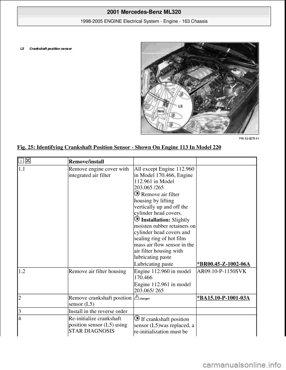
Fig. 25: Identifying Crankshaft Position Sensor - Shown On Engine 113 In Model 220
Remove/install
1.1Remove engine cover with
integrated air filterAll except Engine 112.960
in Model 170.466, Engine
112.961 in Model
203.065 /265
Remove air filter
housing by lifting
vertically up and off the
cylinder head covers.
Installation: Slightly
moisten rubber retainers on
cylinder head covers and
sealing ring of hot film
mass air flow sensor in the
air filter housing with
lubricating paste
Lubricating paste*BR00.45-Z-1002-06A
1.2Remove air filter housingEngine 112.960 in model
170.466AR09.10-P-1150SVK
Engine 112.961 in model
203.065/ 265
2Remove crankshaft position
sensor (L5) *BA15.10-P-1001-03A
3Install in the reverse order
4Re-initialize crankshaft
position sensor (L5) using
STAR DIAGNOSIS If crankshaft position
sensor (L5)was replaced, a
re-initialization must be
2001 Mercedes-Benz ML320
1998-2005 ENGINE Electrical System - Engine - 163 Chassis
me
Saturday, October 02, 2010 3:18:54 PMPage 43 © 2006 Mitchell Repair Information Company, LLC.
Page 2237 of 4133
Oil replenishments are always only detected once the following
conditions are met:
D
the replenished quantity is
at least 1 l
D
after replenishing the oil, the car must be driven a distance of
at
least 5 km
under
normal driving conditions
at an
oil
temperature of at least 60 °C
.
There are instances, however, in which the readout of the remaining
distance nevertheless appears implausible after replenishing oil;
according to the display, no bonus or only a small bonus has been
issued. This is caused by the fact that the remaining distance is
always only displayed within a range from 15 000 km up to 30 000
km (or 20 000 km up to 40 000 km in the case of engine 668), but
internally the system calculates with the actual values which may also
be beyond this range. These internal values can only be displayed
with the HHT.
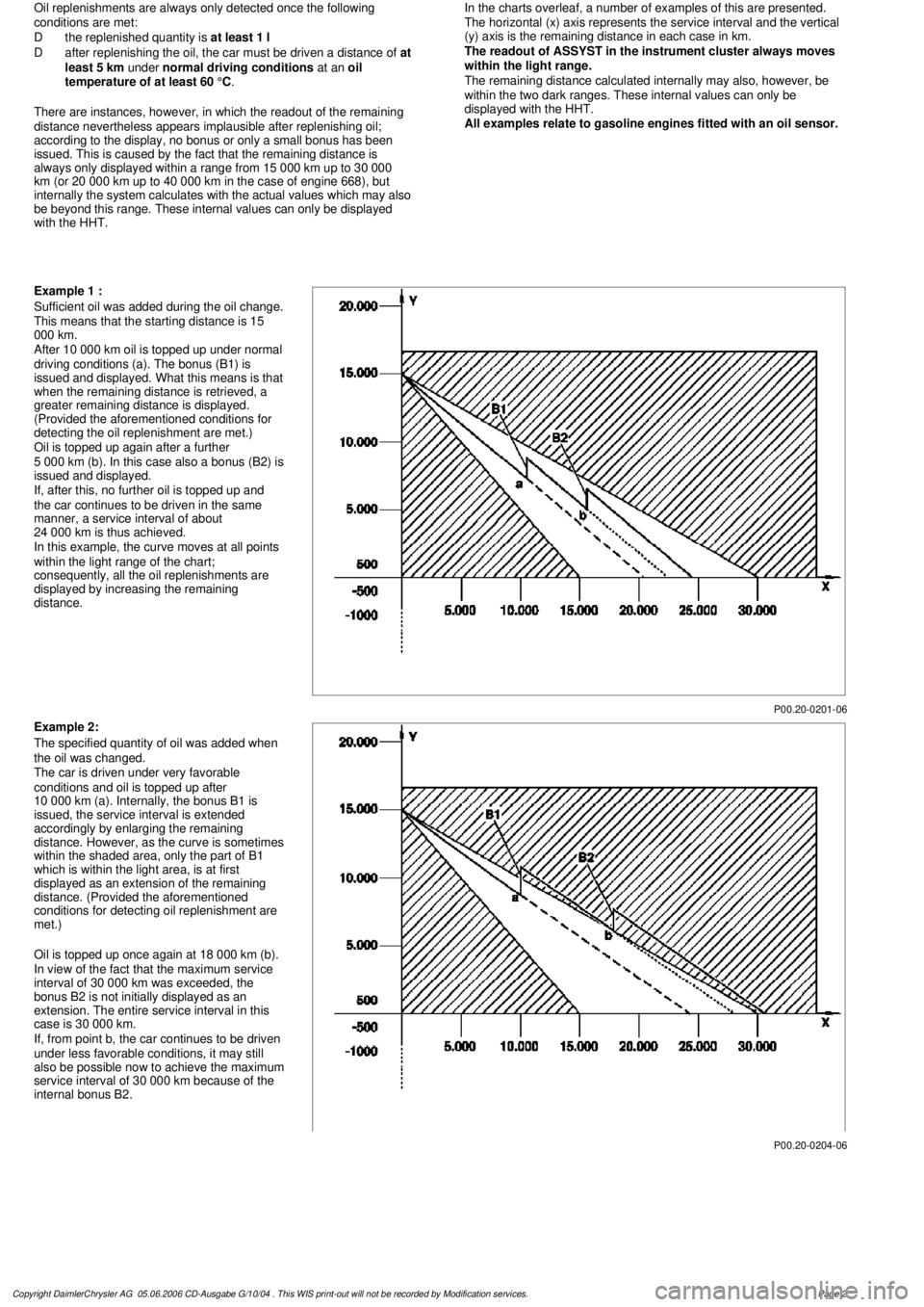
In the charts overleaf, a number of examples of this are presented.
The horizontal (x) axis represents the service interval and the vertical
(y) axis is the remaining distance in each case in km.
The readout of ASSYST in the instrument cluster always moves
within the light range.
The remaining distance calculated internally may also, however, be
within the two dark ranges. These internal values can only be
displayed with the HHT.
All examples relate to gasoline engines fitted with an oil sensor.
P00.20-0201-06
Example 1 :
Sufficient oil was added during the oil change.
This means that the starting distance is 15
000 km.
After 10 000 km oil is topped up under normal
driving conditions (a). The bonus (B1) is
issued and displayed. What this means is that
when the remaining distance is retrieved, a
greater remaining distance is displayed.
(Provided the aforementioned conditions for
detecting the oil replenishment are met.)
Oil is topped up again after a further
5 000 km (b). In this case also a bonus (B2) is
issued and displayed.
If, after this, no further oil is topped up and
the car continues to be driven in the same
manner, a service interval of about
24 000 km is thus achieved.
In this example, the curve moves at all points
within the light range of the chart;
consequently, all the oil replenishments are
displayed by increasing the remaining
distance.
P00.20-0204-06
Example 2:
The specified quantity of oil was added when
the oil was changed.
The car is driven under very favorable
conditions and oil is topped up after
10 000 km (a). Internally, the bonus B1 is
issued, the service interval is extended
accordingly by enlarging the remaining
distance. However, as the curve is sometimes
within the shaded area, only the part of B1
which is within the light area, is at first
displayed as an extension of the remaining
distance. (Provided the aforementioned
conditions for detecting oil replenishment are
met.)
Oil is topped up once again at 18 000 km (b).
In view of the fact that the maximum service
interval of 30 000 km was exceeded, the
bonus B2 is not initially displayed as an
extension. The entire service interval in this
case is 30 000 km.
If, from point b, the car continues to be driven
under less favorable conditions, it may still
also be possible now to achieve the maximum
service interval of 30 000 km because of the
internal bonus B2.
Copyright DaimlerChrysler AG 05.06.2006 CD-Ausgabe G/10/04 . This WIS print-out will not be recorde
d by Modification services.
Page 2
Page 2238 of 4133
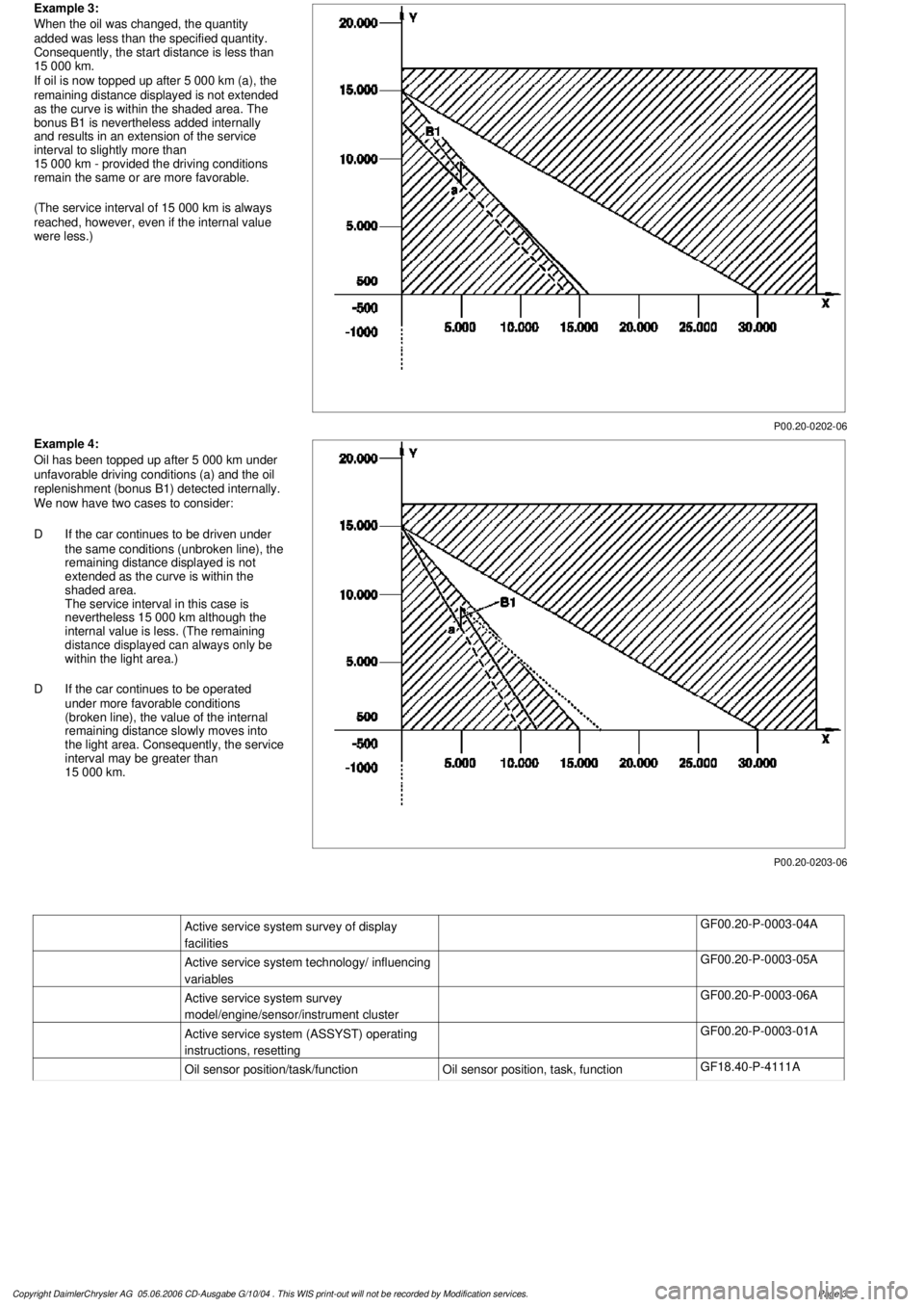
P00.20-0202-06
Example 3:
When the oil was changed, the quantity
added was less than the specified quantity.
Consequently, the start distance is less than
15 000 km.
If oil is now topped up after 5 000 km (a), the
remaining distance displayed is not extended
as the curve is within the shaded area. The
bonus B1 is nevertheless added internally
and results in an extension of the service
interval to slightly more than
15 000 km - provided the driving conditions
remain the same or are more favorable.
(The service interval of 15 000 km is always
reached, however, even if the internal value
were less.)
P00.20-0203-06
Example 4:
Oil has been topped up after 5 000 km under
unfavorable driving conditions (a) and the oil
replenishment (bonus B1) detected internally.
We now have two cases to consider:
D
If the car continues to be driven under
the same conditions (unbroken line), the
remaining distance displayed is not
extended as the curve is within the
shaded area.
The service interval in this case is
nevertheless 15 000 km although the
internal value is less. (The remaining
distance displayed can always only be
within the light area.)
D
If the car continues to be operated
under more favorable conditions
(broken line), the value of the internal
remaining distance slowly moves into
the light area. Consequently, the service
interval may be greater than
15 000 km.
Active service system survey of display
facilities
GF00.20-P-0003-04A
Active service system technology/ influencing
variables
GF00.20-P-0003-05A
Active service system survey
model/engine/sensor/instrument cluster
GF00.20-P-0003-06A
Active service system (ASSYST) operating
instructions, resetting
GF00.20-P-0003-01A
Oil sensor position/task/function
Oil sensor position, task, function
GF18.40-P-4111A
Copyright DaimlerChrysler AG 05.06.2006 CD-Ausgabe G/10/04 . This WIS print-out will not be recorde
d by Modification services.
Page 3
Page 2381 of 4133
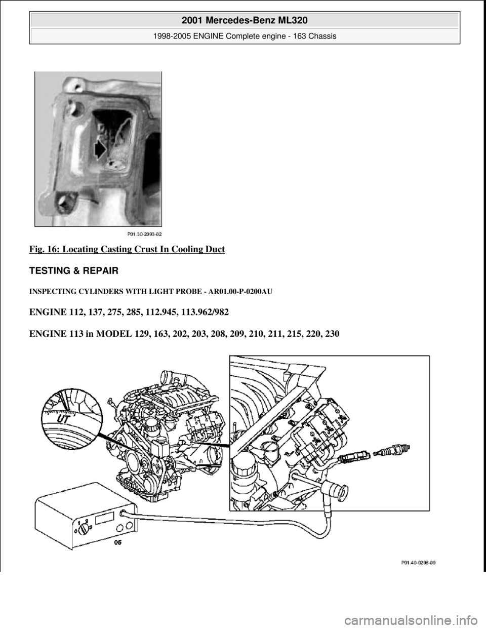
Fig. 16: Locating Casting Crust In Cooling Duct
TESTING & REPAIR
INSPECTING CY LINDERS WITH LIGHT PROBE - AR01.00-P-0200AU
ENGINE 112, 137, 275, 285, 112.945, 113.962/982
ENGINE 113 in MODEL 129, 163, 202, 203, 208, 209, 210, 211, 215, 220, 230
2001 Mercedes-Benz ML320
1998-2005 ENGINE Complete engine - 163 Chassis
me
Saturday, October 02, 2010 3:17:56 PMPage 25 © 2006 Mitchell Repair Information Company, LLC.
Page 2382 of 4133
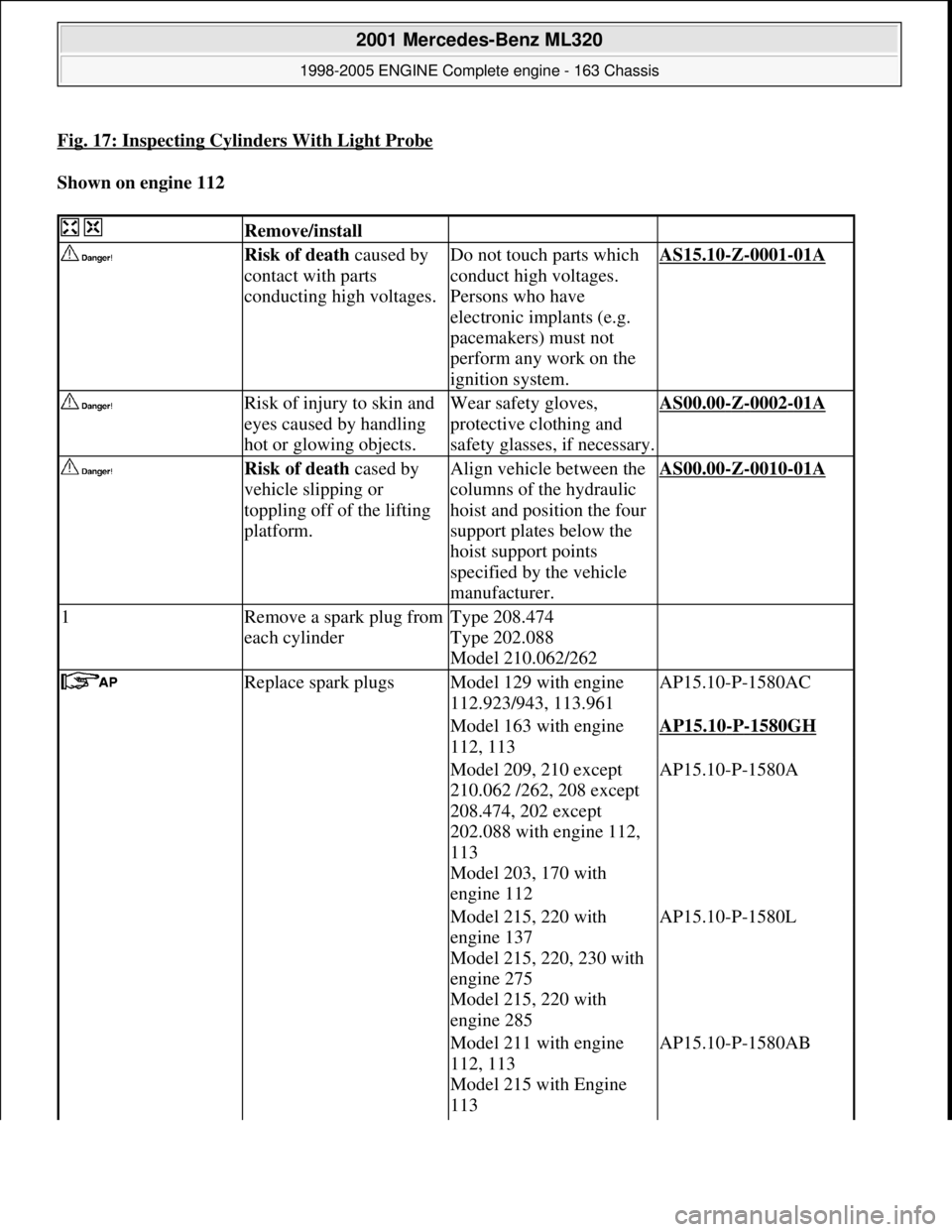
Fig. 17: Inspecting Cylinders With Light Probe
Shown on engine 112
Remove/install
Risk of death caused by
contact with parts
conducting high voltages.Do not touch parts which
conduct high voltages.
Persons who have
electronic implants (e.g.
pacemakers) must not
perform any work on the
ignition system.AS15.10-Z-0001-01A
Risk of injury to skin and
eyes caused by handling
hot or glowing objects.Wear safety gloves,
protective clothing and
safety glasses, if necessary.AS00.00-Z-0002-01A
Risk of death cased by
vehicle slipping or
toppling off of the lifting
platform.Align vehicle between the
columns of the hydraulic
hoist and position the four
support plates below the
hoist support points
specified by the vehicle
manufacturer.AS00.00-Z-0010-01A
1Remove a spark plug from
each cylinderType 208.474
Type 202.088
Model 210.062/262
Replace spark plugsModel 129 with engine
112.923/943, 113.961AP15.10-P-1580AC
Model 163 with engine
112, 113AP15.10-P-1580GH
Model 209, 210 except
210.062 /262, 208 except
208.474, 202 except
202.088 with engine 112,
113
Model 203, 170 with
engine 112AP15.10-P-1580A
Model 215, 220 with
engine 137
Model 215, 220, 230 with
engine 275
Model 215, 220 with
engine 285AP15.10-P-1580L
Model 211 with engine
112, 113
Model 215 with Engine
113 AP15.10-P-1580AB
2001 Mercedes-Benz ML320
1998-2005 ENGINE Complete engine - 163 Chassis
me
Saturday, October 02, 2010 3:17:56 PMPage 26 © 2006 Mitchell Repair Information Company, LLC.
Page 2383 of 4133
Model 220 with engine
112, 113
Model 230 with engine
112, 113
Model 240 with engine
285AP15.10-P-1580H
Model 463 with Engine
112, 113AP15.10-P-1580GA
2.1Remove bottom engine
compartment panelingModel 240AR61.20-P-1105H
3Position piston of cylinder
to be inspected to BDCTo do this, crank the
engine at the central bolt of
the crankshaft in the
direction of rotation of the
engine: ?
Firing orderAR01.00-P-1300-03HA
4Connect cylinder
inspection lamp (05) and
insert the flexible test
probe for the inspection
lamp via the spark plug
bore into the respective
cylinder Cylinder inspection
equipment*WH58.30-Z-1014-05A
Flexible inspection light*WH58.30-Z-1006-05A
Flexible inspection light*WH58.30-Z-1007-05A
Check
5Inspect cylinder walls Normal condition:
Mat-grey surface, no
honing pattern.
If the condition of the
cylinder wall is not clearly
recognizable: ?
Model 129, 163, 170, 202,
203, 208, 209, 210,
215,220,230,463
Remove cylinder head
Model 129 with engine
112, 113AR01.30-P-5800B
Model 202, 208, 210 with
engine 113
Model 163 with engine
112, 113AR01.30-P-5800MV
Model 170, 202, 208, 210
with engine 112AR01.30-P-5800BA
Model 220 with engine
112, 113
Model 230 with engine
2001 Mercedes-Benz ML320
1998-2005 ENGINE Complete engine - 163 Chassis
me
Saturday, October 02, 2010 3:17:56 PMPage 27 © 2006 Mitchell Repair Information Company, LLC.