Page 1770 of 4133
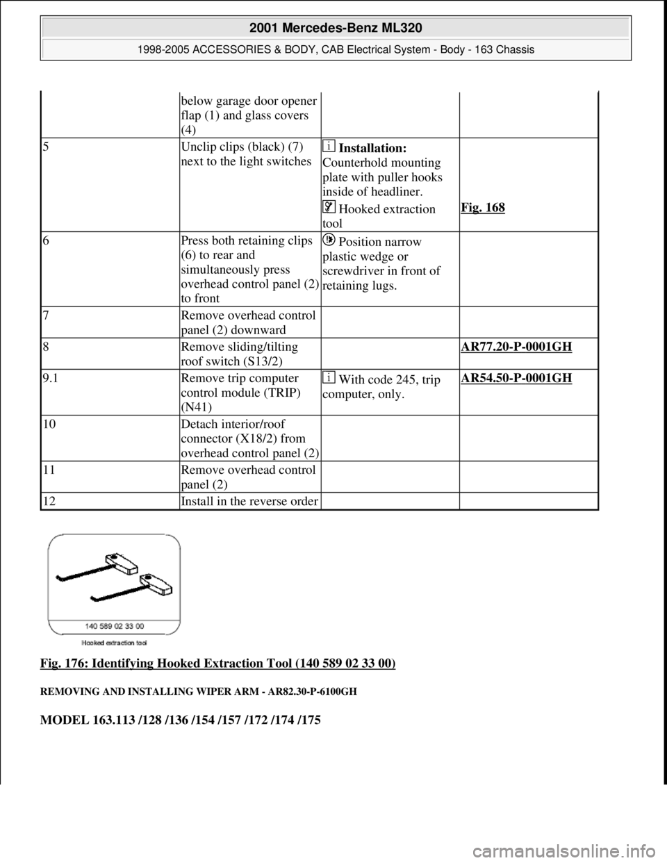
Fig. 176: Identifying Hooked Extraction Tool (140 589 02 33 00)
REMOVING AND INSTALLING WIPER ARM - AR82.30-P-6100GH
MODEL 163.113 /128 /136 /154 /157 /172 /174 /175
below garage door opener
flap (1) and glass covers
(4)
5Unclip clips (black) (7)
next to the light switches Installation:
Counterhold mounting
plate with puller hooks
inside of headliner.
Hooked extraction
toolFig. 168
6Press both retaining clips
(6) to rear and
simultaneously press
overhead control panel (2)
to front Position narrow
plastic wedge or
screwdriver in front of
retaining lugs.
7Remove overhead control
panel (2) downward
8Remove sliding/tilting
roof switch (S13/2) AR77.20-P-0001GH
9.1Remove trip computer
control module (TRIP)
(N41) With code 245, trip
computer, only.AR54.50-P-0001GH
10Detach interior/roof
connector (X18/2) from
overhead control panel (2)
11Remove overhead control
panel (2)
12Install in the reverse order
2001 Mercedes-Benz ML320
1998-2005 ACCESSORIES & BODY, CAB Electrical System - Body - 163 Chassis
me
Saturday, October 02, 2010 3:30:09 PMPage 275 © 2006 Mitchell Repair Information Company, LLC.
Page 1812 of 4133
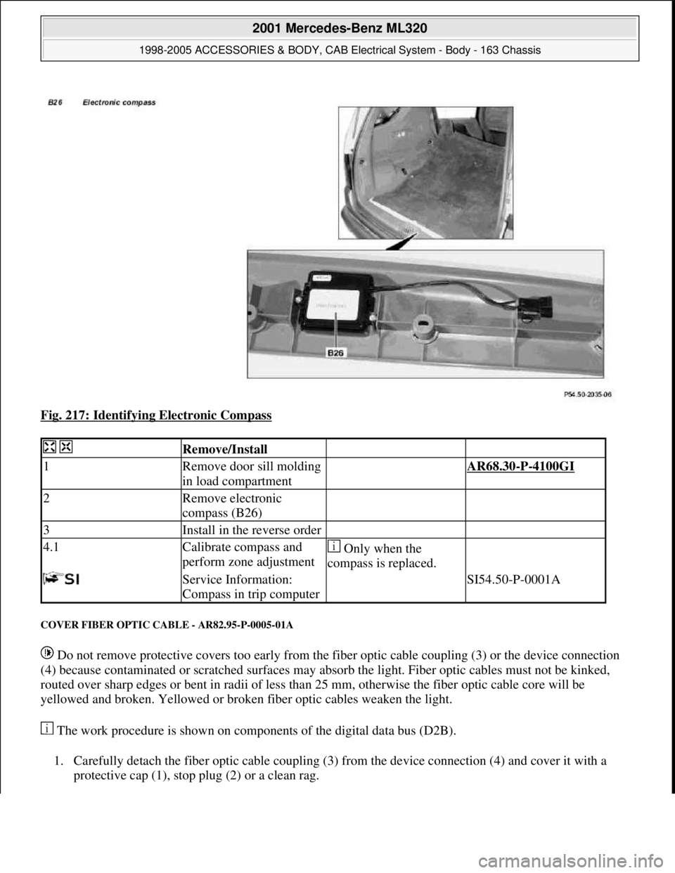
Fig. 217: Identifying Electronic Compass
COVER FIBER OPTIC CABLE - AR82.95-P-0005-01A
Do not remove protective covers too early from the fiber optic cable coupling (3) or the device connection
(4) because contaminated or scratched surfaces may absorb the light. Fiber optic cables must not be kinked,
routed over sharp edges or bent in radii of less than 25 mm, otherwise the fiber optic cable core will be
yellowed and broken. Yellowed or broken fiber optic cables weaken the light.
The work procedure is shown on components of the digital data bus (D2B).
1. Carefully detach the fiber optic cable coupling (3) from the device connection (4) and cover it with a
protective cap (1), stop plug (2) or a clean rag.
Remove/Install
1Remove door sill molding
in load compartment AR68.30-P-4100GI
2Remove electronic
compass (B26)
3Install in the reverse order
4.1Calibrate compass and
perform zone adjustment Only when the
compass is replaced.
Service Information:
Compass in trip computer SI54.50-P-0001A
2001 Mercedes-Benz ML320
1998-2005 ACCESSORIES & BODY, CAB Electrical System - Body - 163 Chassis
me
Saturday, October 02, 2010 3:30:10 PMPage 317 © 2006 Mitchell Repair Information Company, LLC.
Page 1817 of 4133
Front seats
Seat belts/emergency tensioning retractors
MAINTENANCE
CHECK SETTING OF HIGH BEAM - AP82.10-P-8260-02A
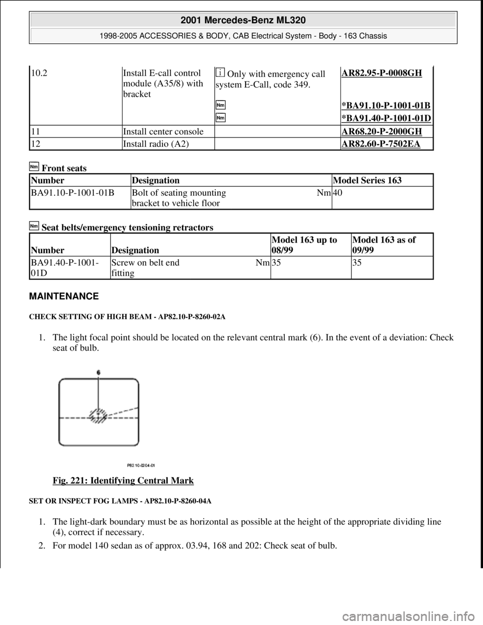
1. The light focal point should be located on the relevant central mark (6). In the event of a deviation: Check
seat of bulb.
Fig. 221: Identifying Central Mark
SET OR INSPECT FOG LAMPS - AP82.10-P-8260-04A
1. The light-dark boundary must be as horizontal as possible at the height of the appropriate dividing line
(4), correct if necessary.
2. For model 140 sedan as of approx. 03.94, 168 and 202: Check seat of bulb.
10.2Install E-call control
module (A35/8) with
bracket Only with emergency call
system E-Call, code 349.AR82.95-P-0008GH
*BA91.10-P-1001-01B
*BA91.40-P-1001-01D
11Install center console AR68.20-P-2000GH
12Install radio (A2) AR82.60-P-7502EA
NumberDesignationModel Series 163
BA91.10-P-1001-01BBolt of seating mounting
bracket to vehicle floorNm40
NumberDesignation
Model 163 up to
08/99Model 163 as of
09/99
BA91.40-P-1001-
01DScrew on belt end
fittingNm3535
2001 Mercedes-Benz ML320
1998-2005 ACCESSORIES & BODY, CAB Electrical System - Body - 163 Chassis
me
Saturday, October 02, 2010 3:30:10 PMPage 322 © 2006 Mitchell Repair Information Company, LLC.
Page 1820 of 4133
Workshop equipment
WINDSHIELD WASHER - CHECKING AND CORRECTING FLUID LEVEL - AP82.35-P-8210GH
MODEL 163
Windshield washer fluid reservoir
Fig. 225: Locating Windshield Washer Fluid Reservoir
3Run engine and switch on
low beam
4Check headlamp range
control for proper
function(except USA)
The light beams from
both headlamps should
change uniformly
5Set headlamp range
control switch to position
0
6Check low beamsAdjust if necessary
(except USA)
Due to the common
reflector unit, the low
beams, high beams and
fog lamps are adjusted
simultaneously.
US version: ?
See "Owner's Manual"AP82.10-P-8260-01A
7Check high beam
adjustment AP82.10-P-8260-02A
8Check fog lamps AP82.10-P-8260-04A
WE58.40-Z-1006-19AHeadlamp adjustment testing unit
2001 Mercedes-Benz ML320
1998-2005 ACCESSORIES & BODY, CAB Electrical System - Body - 163 Chassis
me
Saturday, October 02, 2010 3:30:10 PMPage 325 © 2006 Mitchell Repair Information Company, LLC.
Page 1843 of 4133
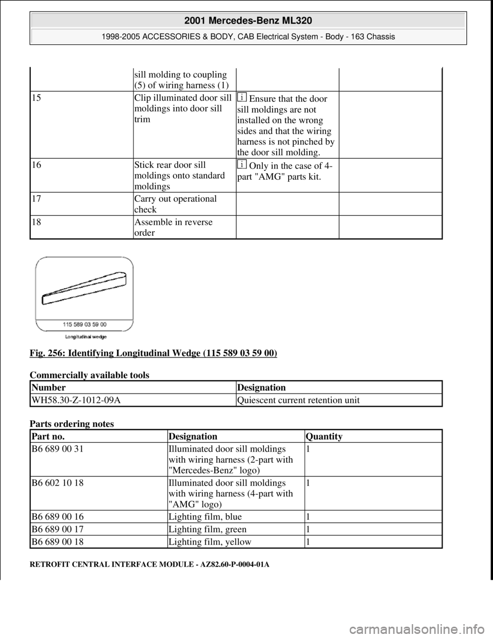
Fig. 256: Identifying Longitudinal Wedge (115 589 03 59 00)
Commercially available tools
Parts ordering notes
RETROFIT CENTRAL INTERFACE MODULE - AZ82.60-P-0004-01A
sill molding to coupling
(5) of wiring harness (1)
15Clip illuminated door sill
moldings into door sill
trim Ensure that the door
sill moldings are not
installed on the wrong
sides and that the wiring
harness is not pinched by
the door sill molding.
16Stick rear door sill
moldings onto standard
moldings Only in the case of 4-
part "AMG" parts kit.
17Carry out operational
check
18Assemble in reverse
order
NumberDesignation
WH58.30-Z-1012-09AQuiescent current retention unit
Part no.DesignationQuantity
B6 689 00 31Illuminated door sill moldings
with wiring harness (2-part with
"Mercedes-Benz" logo)1
B6 602 10 18Illuminated door sill moldings
with wiring harness (4-part with
"AMG" logo)1
B6 689 00 16Lighting film, blue1
B6 689 00 17Lighting film, green1
B6 689 00 18Lighting film, yellow1
2001 Mercedes-Benz ML320
1998-2005 ACCESSORIES & BODY, CAB Electrical System - Body - 163 Chassis
me
Saturday, October 02, 2010 3:30:11 PMPage 348 © 2006 Mitchell Repair Information Company, LLC.
Page 1852 of 4133
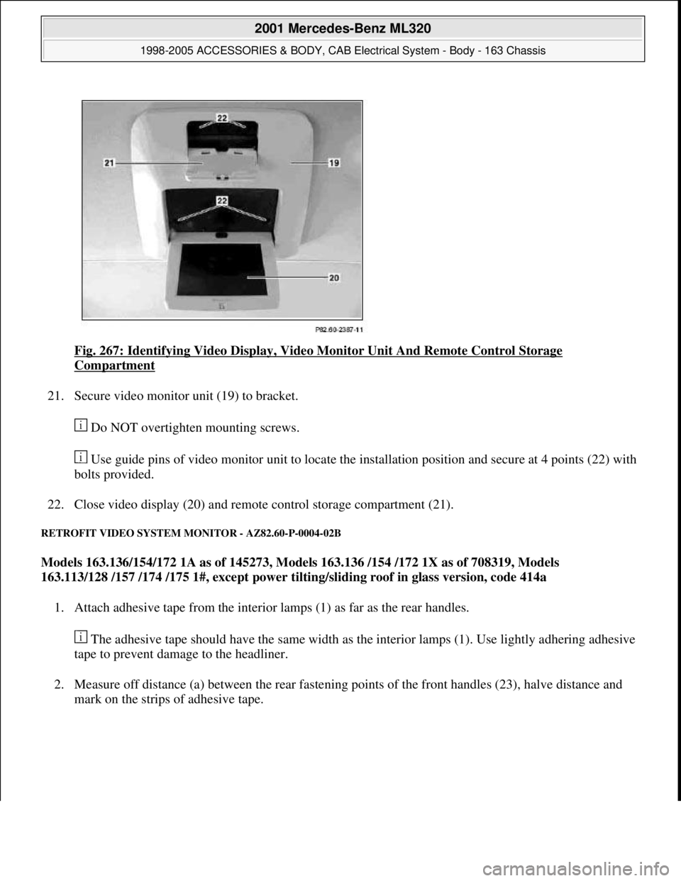
Fig. 267: Identifying Video Display, Video Monitor Unit And Remote Control Storage
Compartment
21. Secure video monitor unit (19) to bracket.
Do NOT overtighten mounting screws.
Use guide pins of video monitor unit to locate the installation position and secure at 4 points (22) with
bolts provided.
22. Close video display (20) and remote control storage compartment (21).
RETROFIT VIDEO SYSTEM MONITOR - AZ82.60-P-0004-02B
Models 163.136/154/172 1A as of 145273, Models 163.136 /154 /172 1X as of 708319, Models
163.113/128 /157 /174 /175 1#, except power tilting/sliding roof in glass version, code 414a
1. Attach adhesive tape from the interior lamps (1) as far as the rear handles.
The adhesive tape should have the same width as the interior lamps (1). Use lightly adhering adhesive
tape to prevent damage to the headliner.
2. Measure off distance (a) between the rear fastening points of the front handles (23), halve distance and
mark on the strips of adhesive tape.
2001 Mercedes-Benz ML320
1998-2005 ACCESSORIES & BODY, CAB Electrical System - Body - 163 Chassis
me
Saturday, October 02, 2010 3:30:11 PMPage 357 © 2006 Mitchell Repair Information Company, LLC.
Page 1853 of 4133
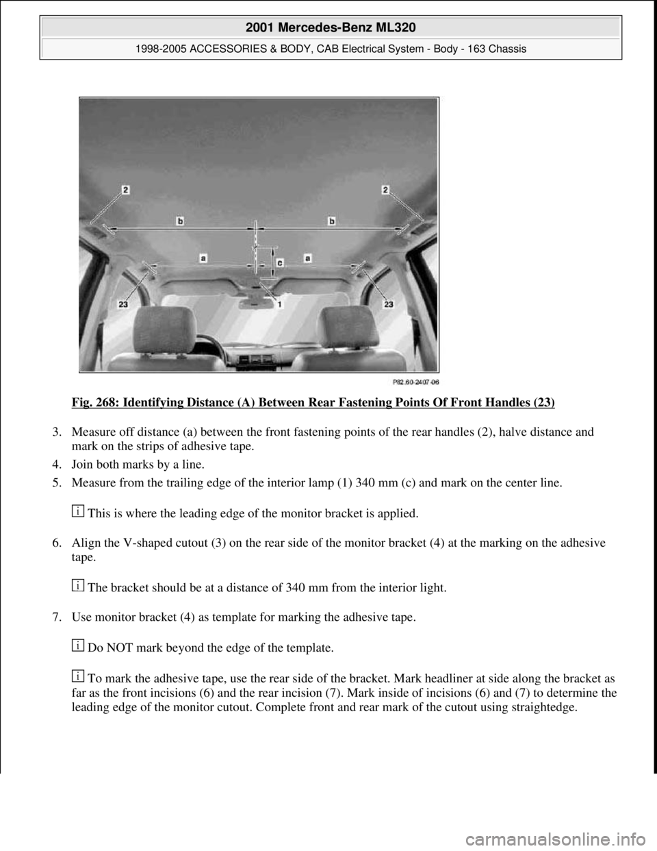
Fig. 268: Identifying Distance (A) Between Rear Fastening Points Of Front Handles (23)
3. Measure off distance (a) between the front fastening points of the rear handles (2), halve distance and
mark on the strips of adhesive tape.
4. Join both marks by a line.
5. Measure from the trailing edge of the interior lamp (1) 340 mm (c) and mark on the center line.
This is where the leading edge of the monitor bracket is applied.
6. Align the V-shaped cutout (3) on the rear side of the monitor bracket (4) at the marking on the adhesive
tape.
The bracket should be at a distance of 340 mm from the interior light.
7. Use monitor bracket (4) as template for marking the adhesive tape.
Do NOT mark beyond the edge of the template.
To mark the adhesive tape, use the rear side of the bracket. Mark headliner at side along the bracket as
far as the front incisions (6) and the rear incision (7). Mark inside of incisions (6) and (7) to determine the
leading edge of the monitor cutout. Complete front and rear mark of the cutout using straightedge.
2001 Mercedes-Benz ML320
1998-2005 ACCESSORIES & BODY, CAB Electrical System - Body - 163 Chassis
me
Saturday, October 02, 2010 3:30:11 PMPage 358 © 2006 Mitchell Repair Information Company, LLC.
Page 1864 of 4133
Fig. 281: Identifying Video Display, Video Monitor Unit And Remote Control Storage
Compartment
RETROFIT VIDEO SYSTEM MONITOR - AZ82.60-P-0004-02D
Model 163.136 /154 /172 2A as of 145273, Models 163.136 /154 /172 2X as of 708319, Models
163.113/128 /157 /174 /175 2#, except power tilting/sliding roof in glass version, Code 414a
1. Attach adhesive tape from the interior lamps (1) as far as the rear handles.
The adhesive tape should have the same width as the interior lamps (1). Use lightly adhering adhesive
tape to prevent damage to the headliner.
2. Measure off distance (a) between the rear fastening points of the front handles (23), halve distance and
mark on the strips of adhesive tape.
2001 Mercedes-Benz ML320
1998-2005 ACCESSORIES & BODY, CAB Electrical System - Body - 163 Chassis
me
Saturday, October 02, 2010 3:30:11 PMPage 369 © 2006 Mitchell Repair Information Company, LLC.