Page 1917 of 4133
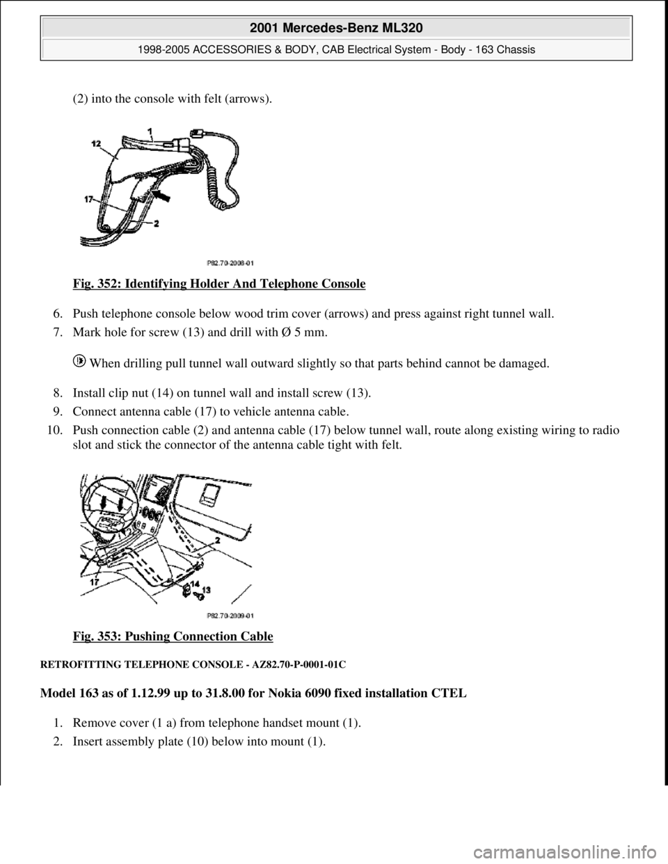
(2) into the console with felt (arrows).
Fig. 352: Identifying Holder And Telephone Console
6. Push telephone console below wood trim cover (arrows) and press against right tunnel wall.
7. Mark hole for screw (13) and drill with Ø 5 mm.
When drilling pull tunnel wall outward slightly so that parts behind cannot be damaged.
8. Install clip nut (14) on tunnel wall and install screw (13).
9. Connect antenna cable (17) to vehicle antenna cable.
10. Push connection cable (2) and antenna cable (17) below tunnel wall, route along existing wiring to radio
slot and stick the connector of the antenna cable tight with felt.
Fig. 353: Pushing Connection Cable
RETROFITTING TELEPHONE CONSOLE - AZ82.70-P-0001-01C
Model 163 as of 1.12.99 up to 31.8.00 for Nokia 6090 fixed installation CTEL
1. Remove cover (1 a) from telephone handset mount (1).
2. Insert assembly plate (10) below into mount (1).
2001 Mercedes-Benz ML320
1998-2005 ACCESSORIES & BODY, CAB Electrical System - Body - 163 Chassis
me
Saturday, October 02, 2010 3:30:13 PMPage 422 © 2006 Mitchell Repair Information Company, LLC.
Page 1919 of 4133
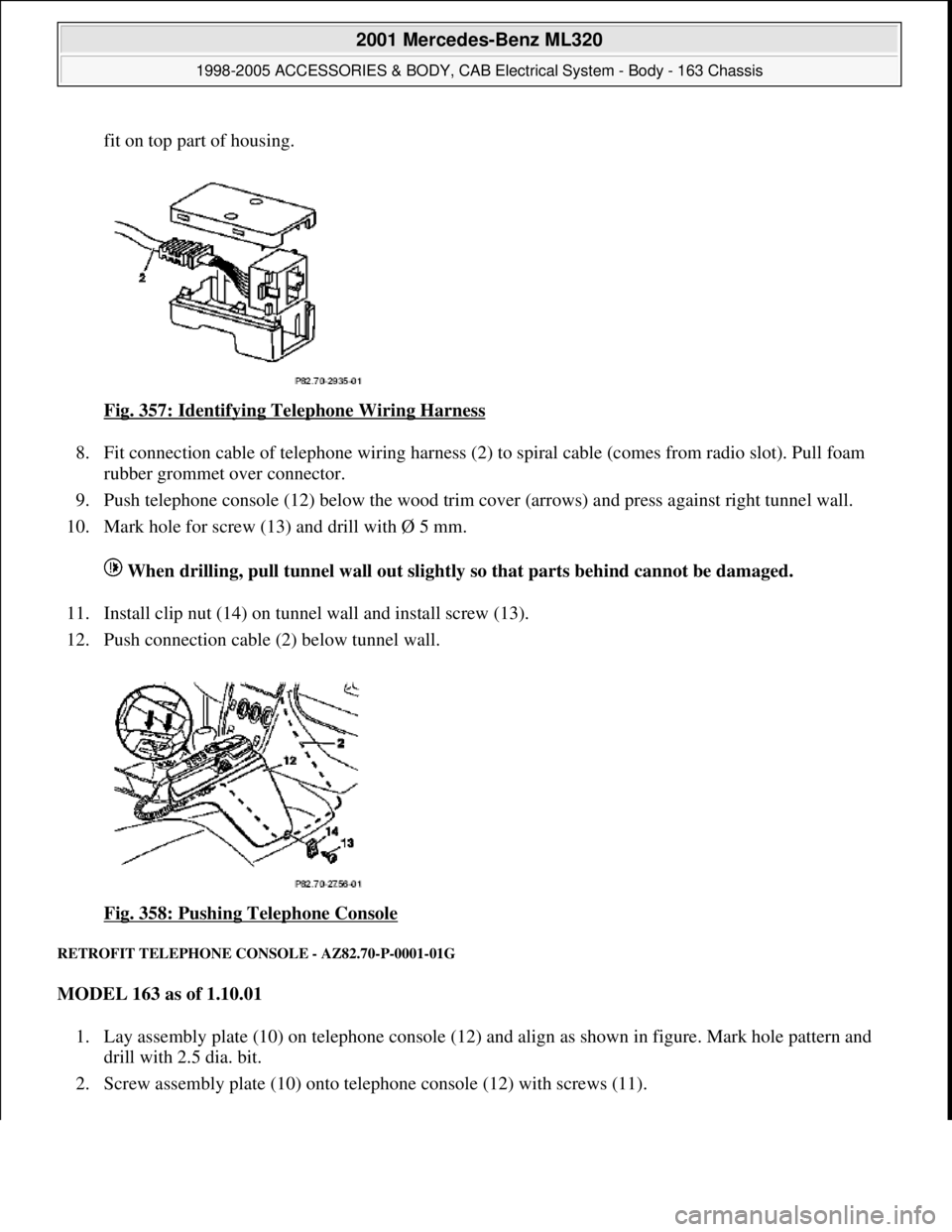
fit on top part of housing.
Fig. 357: Identifying Telephone Wiring Harness
8. Fit connection cable of telephone wiring harness (2) to spiral cable (comes from radio slot). Pull foam
rubber grommet over connector.
9. Push telephone console (12) below the wood trim cover (arrows) and press against right tunnel wall.
10. Mark hole for screw (13) and drill with Ø 5 mm.
When drilling, pull tunnel wall out slightly so that parts behind cannot be damaged.
11. Install clip nut (14) on tunnel wall and install screw (13).
12. Push connection cable (2) below tunnel wall.
Fig. 358: Pushing Telephone Console
RETROFIT TELEPHONE CONSOLE - AZ82.70-P-0001-01G
MODEL 163 as of 1.10.01
1. Lay assembly plate (10) on telephone console (12) and align as shown in figure. Mark hole pattern and
drill with 2.5 dia. bit.
2. Screw assembly plate (10) onto telephone console (12) with screws (11).
2001 Mercedes-Benz ML320
1998-2005 ACCESSORIES & BODY, CAB Electrical System - Body - 163 Chassis
me
Saturday, October 02, 2010 3:30:13 PMPage 424 © 2006 Mitchell Repair Information Company, LLC.
Page 1943 of 4133
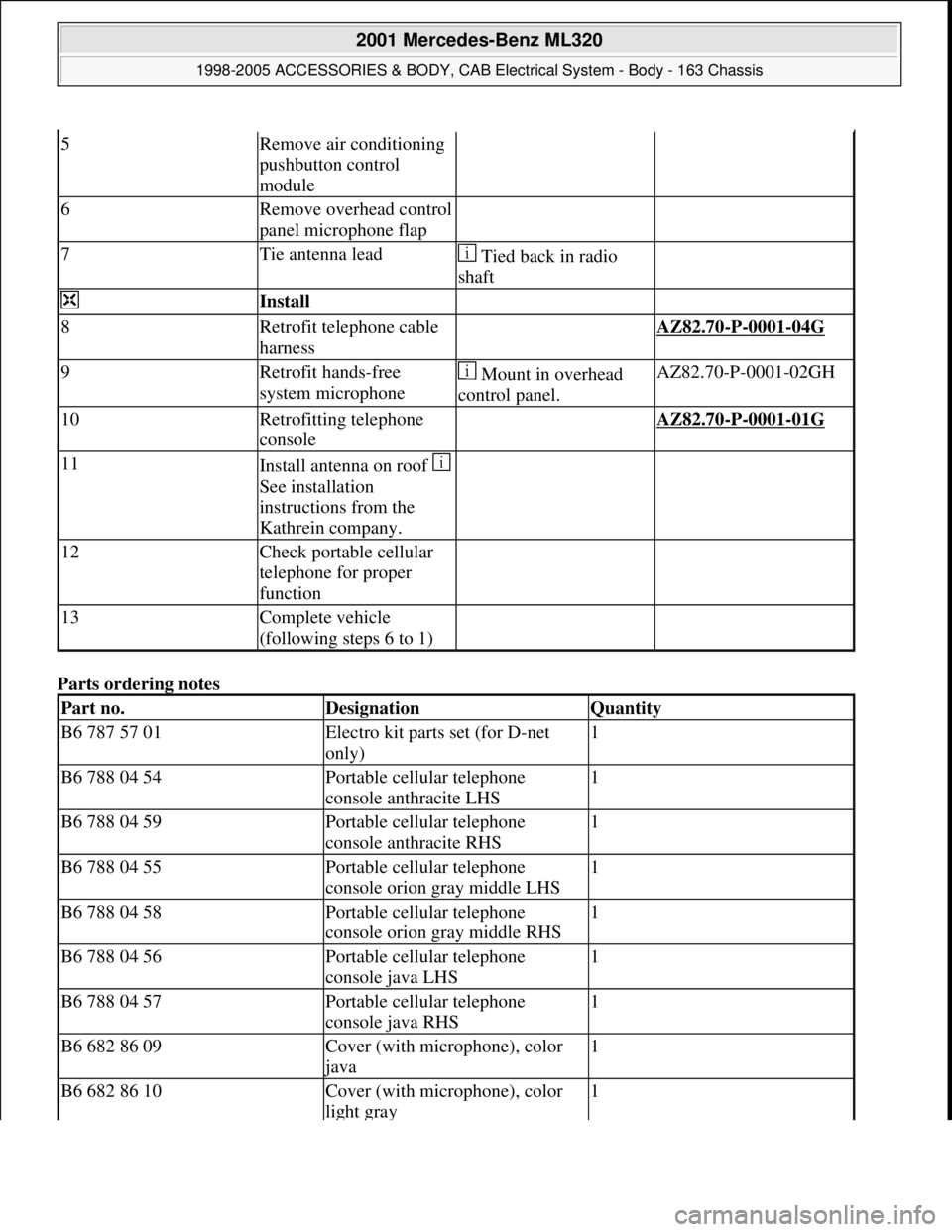
Parts ordering notes
5Remove air conditioning
pushbutton control
module
6Remove overhead control
panel microphone flap
7Tie antenna lead Tied back in radio
shaft
Install
8Retrofit telephone cable
harness AZ82.70-P-0001-04G
9Retrofit hands-free
system microphone Mount in overhead
control panel.AZ82.70-P-0001-02GH
10Retrofitting telephone
console AZ82.70-P-0001-01G
11Install antenna on roof
See installation
instructions from the
Kathrein company.
12Check portable cellular
telephone for proper
function
13Complete vehicle
(following steps 6 to 1)
Part no.DesignationQuantity
B6 787 57 01Electro kit parts set (for D-net
only)1
B6 788 04 54Portable cellular telephone
console anthracite LHS1
B6 788 04 59Portable cellular telephone
console anthracite RHS1
B6 788 04 55Portable cellular telephone
console orion gray middle LHS1
B6 788 04 58Portable cellular telephone
console orion gray middle RHS1
B6 788 04 56Portable cellular telephone
console java LHS1
B6 788 04 57Portable cellular telephone
console java RHS1
B6 682 86 09Cover (with microphone), color
java
1
B6 682 86 10Cover (with microphone), color
light gray1
2001 Mercedes-Benz ML320
1998-2005 ACCESSORIES & BODY, CAB Electrical System - Body - 163 Chassis
me
Saturday, October 02, 2010 3:30:14 PMPage 448 © 2006 Mitchell Repair Information Company, LLC.
Page 1951 of 4133
RETROFIT WIRING HARNESS OF HANDS-FREE SYSTEM - AZ82.70-P-0005-02GH
1. Expose connector for telephone handset (A34) in radio shaft.
Fig. 402: Identifying Telephone Handset Connector (A34)
2. Connect connector (8) to interface (4).
3. Connect antenna for telephone handset (A34).
4. Connect connection line (5) to interface (4).
B6 788 0388FA console RHS (java)1
A005 997 9390Tie strap5
B6 682 8607Wiring harness (tel. on radio)1
B6 682 8608CTEL antenna1
B6 682 8609Cover (with microphone), color:
java (as of 01/01)
1
B6 682 8610Cover (without microphone)
color: light gray (as of 01/01)1
B6 682 8611Active microphone in design
function housing (up to 12/00)1
2001 Mercedes-Benz ML320
1998-2005 ACCESSORIES & BODY, CAB Electrical System - Body - 163 Chassis
me
Saturday, October 02, 2010 3:30:14 PMPage 456 © 2006 Mitchell Repair Information Company, LLC.
Page 1959 of 4133
REMOVAL & INSTALLATION
INSTALLING LARGER WASHER FLUID RESERVOIR - SM82.35-P-0002GH
MODELS 163.113/136/154/172
with 5 I container
The 5 I washer fluid reservoir has been replaced by a 7.6 I container. If a 5 l container is replaced, then the
following modifications must be made.
This modification should ONLY be performed following a customer complaint.
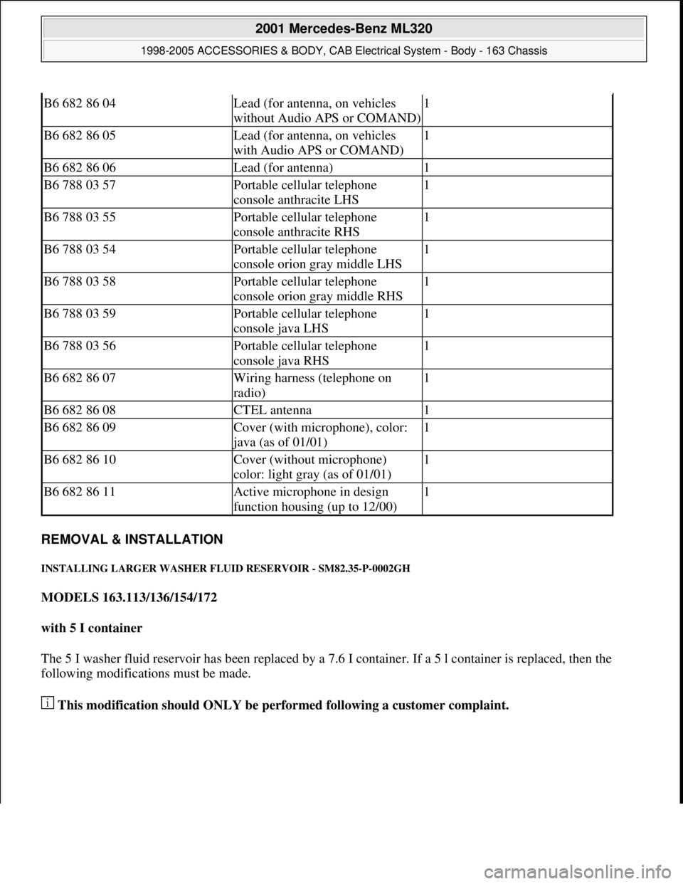
B6 682 86 04Lead (for antenna, on vehicles
without Audio APS or COMAND)1
B6 682 86 05Lead (for antenna, on vehicles
with Audio APS or COMAND)1
B6 682 86 06Lead (for antenna)1
B6 788 03 57Portable cellular telephone
console anthracite LHS1
B6 788 03 55Portable cellular telephone
console anthracite RHS1
B6 788 03 54Portable cellular telephone
console orion gray middle LHS1
B6 788 03 58Portable cellular telephone
console orion gray middle RHS1
B6 788 03 59Portable cellular telephone
console java LHS1
B6 788 03 56Portable cellular telephone
console java RHS1
B6 682 86 07Wiring harness (telephone on
radio)1
B6 682 86 08CTEL antenna1
B6 682 86 09Cover (with microphone), color:
java (as of 01/01)
1
B6 682 86 10Cover (without microphone)
color: light gray (as of 01/01)1
B6 682 86 11Active microphone in design
function housing (up to 12/00)1
2001 Mercedes-Benz ML320
1998-2005 ACCESSORIES & BODY, CAB Electrical System - Body - 163 Chassis
me
Saturday, October 02, 2010 3:30:14 PMPage 464 © 2006 Mitchell Repair Information Company, LLC.
Page 1968 of 4133
AP82.10-P-8260-04A
Set or inspect fog lamps
P82.10-0205-01
1
The light-dark boundary must be as horizontal as possible at the height of the appropriate
dividing line (4), correct if necessary.
2
For model 140 sedan as of approx. 03.94, 168 and 202: Check seat of bulb.
P82.10-3633-01
Model 163.113 /154 #A as of 289565,
163.113 #X as of 754620,
163.128 /154 /157 /175 except CODE (U49) Styling package
Arrow:
Position of adjusting screw
Copyright DaimlerChrysler AG 20.05.2006 CD-Ausgabe G/10/04 . This WIS print-out will not be recorde
d by Modification services.
Page 1
Page 1970 of 4133
AP82.10-P-8260GH
Check and correct headlamp adjustment
2.7.97
MODEL
163
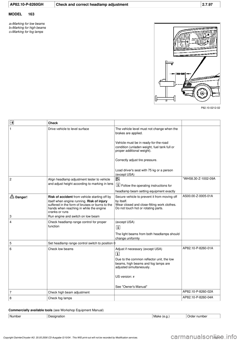
a=Marking for low beams
b=Marking for high beams
c=Marking for fog lamps
P82.10-0212-02
Check
1
Drive vehicle to level surface
The vehicle level must not change when the
brakes are applied.
Vehicle must be in ready-for-the-road
condition (unladen weight, fuel tank full or
proper additional weight).
Correctly adjust tire pressure.
Load driver's seat with 75 kg or a person
(except USA)
2
Align headlamp adjustment tester to vehicle
and adjust height according to marking in lens
Follow the operating instructions for
headlamp beam setting equipment exactly
*WH58.30-Z-1002-09A
Danger!
Risk of accident
from vehicle starting off by
itself when engine running.
Risk of injury
suffered in the form of bruises or burns to the
hands when reaching in while the engine
cranks or runs
Secure vehicle to prevent it from moving off
by itself.
Wear closed and close-fitting work clothes.
Do not touch hot or rotating parts.
AS00.00-Z-0005-01A
3
Run engine and switch on low beam
4
Check headlamp range control for proper
function
(except USA)
The light beams from both headlamps should
change uniformly
5
Set headlamp range control switch to position 0
6
Check low beams
Adjust if necessary (except USA)
AP82.10-P-8260-01A
Due to the common reflector unit, the low
beams, high beams and fog lamps are
adjusted simultaneously.
US version:
#
See "Owner's Manual"
7
Check high beam adjustment
AP82.10-P-8260-02A
8
Check fog lamps
AP82.10-P-8260-04A
Commercially available tools
(see Workshop Equipment Manual)
Number
Designation
Make (e.g.)
Order number
Copyright DaimlerChrysler AG 20.05.2006 CD-Ausgabe G/10/04 . This WIS print-out will not be recorde
d by Modification services.
Page 1
Page 2030 of 4133
AR09.41-P-6817MM
Removing and installing charge air cooler
10.11.99
ENGINE
612.963 in MODEL 163.113
P09.41-2024-09
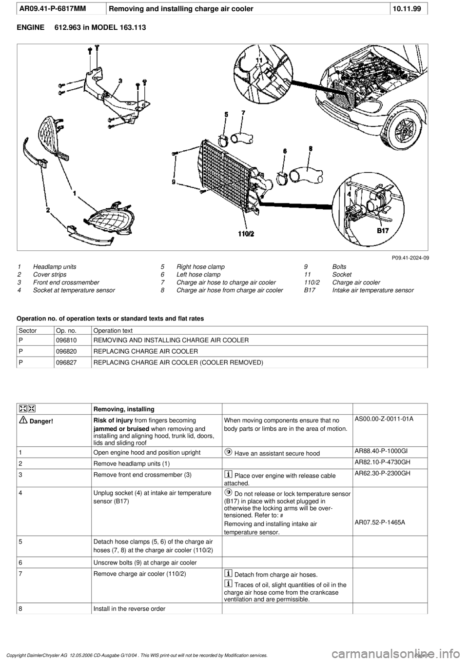
1
Headlamp units
2
Cover strips
3
Front end crossmember
4
Socket at temperature sensor
9
Bolts
11
Socket
110/2
Charge air cooler
B17
Intake air temperature sensor
5
Right hose clamp
6
Left hose clamp
7
Charge air hose to charge air cooler
8
Charge air hose from charge air cooler
Operation no. of operation texts or standard texts and flat rates
Sector
Op. no.
Operation text
P
096810
REMOVING AND INSTALLING CHARGE AIR COOLER
P
096820
REPLACING CHARGE AIR COOLER
P
096827
REPLACING CHARGE AIR COOLER (COOLER REMOVED)
Removing, installing
Danger!
Risk of injury
from fingers becoming
jammed or bruised
when removing and
installing and aligning hood, trunk lid, doors,
lids and sliding roof
When moving components ensure that no
body parts or limbs are in the area of motion.
AS00.00-Z-0011-01A
1
Open engine hood and position upright
Have an assistant secure hood
AR88.40-P-1000GI
2
Remove headlamp units (1)
AR82.10-P-4730GH
3
Remove front end crossmember (3)
Place over engine with release cable
attached.
AR62.30-P-2300GH
4
Unplug socket (4) at intake air temperature
sensor (B17)
Do not release or lock temperature sensor
(B17) in place with socket plugged in
otherwise the locking arms will be over-
tensioned. Refer to:
#
Removing and installing intake air
temperature sensor.
AR07.52-P-1465A
5
Detach hose clamps (5, 6) of the charge air
hoses (7, 8) at the charge air cooler (110/2)
6
Unscrew bolts (9) at charge air cooler
7
Remove charge air cooler (110/2)
Detach from charge air hoses.
Traces of oil, slight quantities of oil in the
charge air hose come from the crankcase
ventilation and are permissible.
8
Install in the reverse order
Copyright DaimlerChrysler AG 12.05.2006 CD-Ausgabe G/10/04 . This WIS print-out will not be recorde
d by Modification services.
Page 1