Page 336 of 4133
286 Technical data
Te ch n ica l
data Instruments
and controlsOperation DrivingInstrument
cluster displayPractical hints Car care Index
Layout of poly-V-belt drive 1Automatic belt tensioner
2Crankshaft
3Air conditioner compressor
4Coolant pump
5Generator (alternator)
6Idler pulley
7Power steering pump
For dimensions of the poly-V-belt, see technical data.
Page 753 of 4133
286
Technical data
Te ch n ica l
data
Instruments
and controls Operation Driving
Instrument
cluster display Practical hints Car care Index
Layout of poly-V-belt drive 1 Automatic belt tensioner
2 Crankshaft
3 Air conditioner compressor
4 Coolant pump
5 Generator (alternator)
6 Idler pulley
7 Power steering pump
For dimensions of the poly-V-belt, see technical data.
Page 1058 of 4133
254 Practical hintsWhat to do if …Problem
Possible cause
Suggested solution
#
The red charge indicator lamp
comes on when the engine is
running.
The battery is no longer charging.
Possible causes:�
alternator malfunctioning
�
broken poly-V-belt
�
Stop immediately and check the
poly-V-belt.
If it is broken
�
Do not continue to drive, before the
poly-V-belt is replaced.
Notify an authorized Mercedes-Benz
Light Truck Center.
2
The yellow brake indicator lamp
comes on during braking or after
starting the engine.
The brake pads are worn down.
�
Have the system checked at an autho-
rized Mercedes-Benz Light Truck
Center.
!Brake pad thickness must be visually
checked by a qualified technician at the
intervals specified in the Service book-
let.
Page 1097 of 4133
293 Technical data
Layout of poly-V-belt drive
�Layout of poly-V-belt drive
1Automatic belt tensioner
2Power steering pump
3Air conditioning compressor
4Crankshaft
5Coolant pump
6Generator (alternator)
7Idler pulley
Page 1118 of 4133

314 Technical termsPoly-V-belt drive
Drives engine-components (alternator,
AC compressor, etc.) from the engine.
Power train
Collective term designating all compo-
nents used to generate and transmit
motive power to the drive axles, includ-
ing
�
engine
�
clutch / torque converter
�
transmission
�
transfer case
�
drive shaft
�
differential
�
axle shafts / axlesRemote Vehicle Diagnostics
Transmission of vehicle data and cur-
rent location to the Mercedes-Benz
Customer Assistance Center for sub-
scribers to Tele Aid service.
REST
(Residual engine heat utilization)
Feature that uses the engine heat
stored in the coolant to heat the vehi-
cle interior for a short time after the en-
gine has been turned off.
Restraint system
Seat belts, belt tensioner, airbags and
child seat restraint systems. As inde-
pendent systems, their protective func-
tions complement one another.RON
(R
esearch O
ctane N
umber)
The Research Octane Number for gaso-
line as determined by a standardized
method. It is an indication of a gaso-
line's ability to resist undesired detona-
tion (knocking). The average of both
the ->MON (Motor Octane Number)
and RON (Research Octane Number) is
posted at the pump, also known as
ANTI-KNOCK INDEX.
Shift lock
When the vehicle is parked, this lock
prevents the transmission selector le-
ver from being moved out of positionP
without key turned and brake pedal de-
pressed.
SRS
(S
upplemental R
estraint S
ystem)
Seat belts, emergency tensioning de-
vice and airbags. Though independent
systems, they are closely interfaced to
provide effective occupant protection.
Page 2207 of 4133

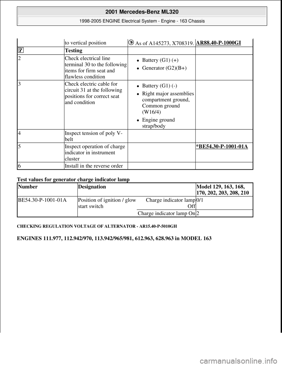
Test values for generator charge indicator lamp
CHECKING REGULATION VOLTAGE OF ALTERNATOR - AR15.40-P-5010GH
ENGINES 111.977, 112.942/970, 113.942/965/981, 612.963, 628.963 in MODEL 163
to vertical position As of A145273, X708319.AR88.40-P-1000GI
Testing
2Check electrical line
terminal 30 to the following
items for firm seat and
flawless conditionBattery (G1) (+)
Generator (G2)(B+)
3Check electric cable for
circuit 31 at the following
positions for correct seat
and conditionBattery (G1) (-)
Right major assemblies
compartment ground,
Common ground
(W16/4)
Engine ground
strap/body
4Inspect tension of poly V-
belt
5Inspect operation of charge
indicator in instrument
cluster *BE54.30-P-1001-01A
6Install in the reverse order
NumberDesignationModel 129, 163, 168,
170, 202, 203, 208, 210
BE54.30-P-1001-01APosition of ignition / glow
start switchCharge indicator lamp
Of
f
0/1
Charge indicator lamp On2
2001 Mercedes-Benz ML320
1998-2005 ENGINE Electrical System - Engine - 163 Chassis
me
Saturday, October 02, 2010 3:18:54 PMPage 53 © 2006 Mitchell Repair Information Company, LLC.
Page 2216 of 4133

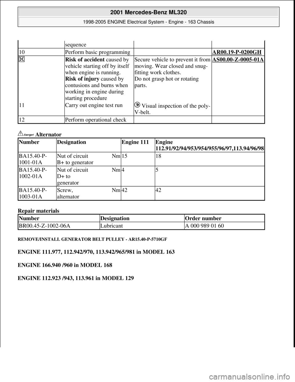
Alternator
Repair materials
REMOVE/INSTALL GENERATOR BELT PULLEY - AR15.40-P-5710GF
ENGINE 111.977, 112.942/970, 113.942/965/981 in MODEL 163
ENGINE 166.940 /960 in MODEL 168
ENGINE 112.923 /943, 113.961 in MODEL 129
sequence
10Perform basic programming AR00.19-P-0200GH
Risk of accident caused by
vehicle starting off by itself
when engine is running.
Risk of injury caused by
contusions and burns when
working in engine during
starting procedureSecure vehicle to prevent it from
moving. Wear closed and snug-
fitting work clothes.
Do not grasp hot or rotating
parts.AS00.00-Z-0005-01A
11Carry out engine test run Visual inspection of the poly-
V-belt.
12Perform operational check
NumberDesignationEngine 111Engine
112.91/92/94/953/954/955/96/97,113.94/96/98
BA15.40-P-
1001-01ANut of circuit
B+ to generatorNm1518
BA15.40-P-
1002-01ANut of circuit
D+ to
generatorNm45
BA15.40-P-
1003-01AScrew,
alternatorNm4242
NumberDesignationOrder number
BR00.45-Z-1002-06ALubricantA 000 989 01 60
2001 Mercedes-Benz ML320
1998-2005 ENGINE Electrical System - Engine - 163 Chassis
me
Saturday, October 02, 2010 3:18:55 PMPage 62 © 2006 Mitchell Repair Information Company, LLC.
Page 2217 of 4133
Fig. 33: Identifying Generator, Belt Pulley And Collar Nut
Fig. 34: Identifying Double He xagon Wrench And Generator
Remove/Install
1Remove alternatorEngine 112, 113 in Model
129.AR15.40-P-5032CT
Engine 166.940 /960 in AR15.40-P-5032GF
2001 Mercedes-Benz ML320
1998-2005 ENGINE Electrical System - Engine - 163 Chassis
me
Saturday, October 02, 2010 3:18:55 PMPage 63 © 2006 Mitchell Repair Information Company, LLC.