1997 MERCEDES-BENZ ML350 sensor
[x] Cancel search: sensorPage 3498 of 4133

AF54.30-P-8400A
Instrument cluster indicates: Oil sensor defective, oil level below min. or oil level
above max. with engine running and at operating temperature. No DTC stored.
19.5.98
MODEL
129.0, 163.1, 202.0, 208.3 /4, 210.0 /2 /6, 220.0 /1 with ENGINE 112
MODEL
129.0, 163.1, 202.0, 208.3 /4, 210.0 /2, 220.0 /1 with ENGINE 113
Damage code
Cause
Remedy
54 201 90
Oil low, connector defective or coding error
1
Shut off engine and wait 2 min. (key
position 0)
Instrument cluster indicates oil sensor
defective, oil level below min. or oil level
above max. with engine warm and running.
No DTC stored in DTC memory!
2
Check oil level with oil dipstick
3
Check oil level on instrument cluster:
- Key in steering wheel lock position 2,
engine not running
- Wait until - - - - - - appears on
instrument cluster
- When this is displayed press the reset
button for the tripodometer twice within
1 sec. (display appears only after
expiration of a waiting time (max. 30
min.) depending on engine oil
temperature)
Oil level is at bottom mark on oil dipstick
and instrument cluster indicates:
-1L
, -
1,5L
or -2L
#
4
Add quantity of oil indicated on
instrument cluster display and repeat
test.
Oil level at upper mark on dipstick and
instrument cluster indicates either oil level
okay or -1L
, -
1,5L
, -2L
#
5
Recode instrument cluster
AF54.30-P-8600A
Problem still present
#
6
Check cable to oil sensor, oil sensor
connectors, control module and fuse
box (see wiring diagram) for good contact
Copyright DaimlerChrysler AG 05.06.2006 CD-Ausgabe G/10/04 . This WIS print-out will not be recorde
d by Modification services.
Page 1
Page 3501 of 4133
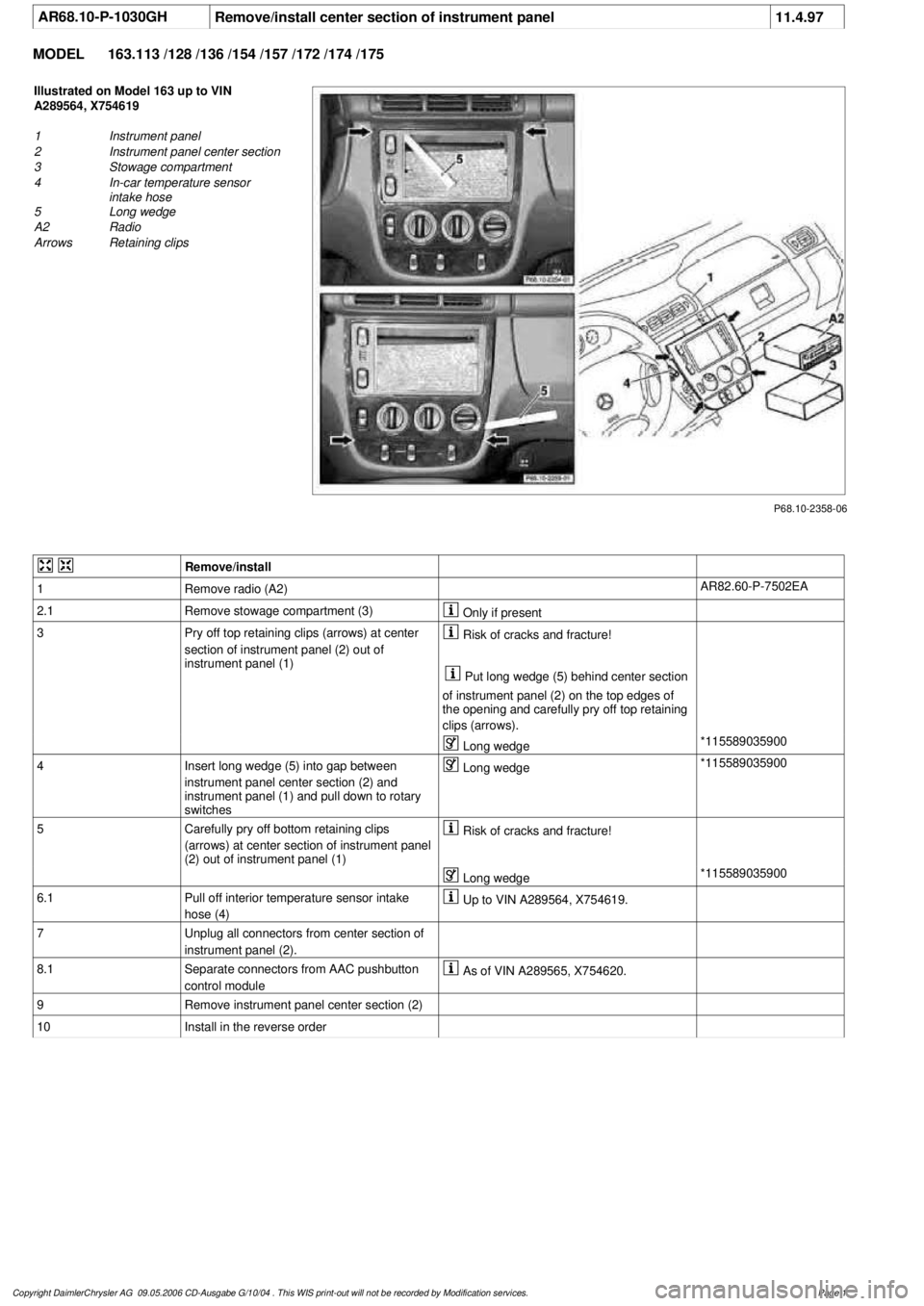
AR68.10-P-1030GH
Remove/install center section of instrument panel
11.4.97
MODEL
163.113 /128 /136 /154 /157 /172 /174 /175
P68.10-2358-06
Illustrated on Model 163 up to VIN
A289564, X754619
1
Instrument panel
2
Instrument panel center section
3
Stowage compartment
4
In-car temperature sensor
intake hose
5
Long wedge
A2
Radio
Arrows
Retaining clips
Remove/install
1
Remove radio (A2)
AR82.60-P-7502EA
2.1
Remove stowage compartment (3)
Only if present
3
Pry off top retaining clips (arrows) at center
section of instrument panel (2) out of
instrument panel (1)
Risk of cracks and fracture!
Put long wedge (5) behind center section
of instrument panel (2) on the top edges of
the opening and carefully pry off top retaining
clips (arrows).
Long wedge
*115589035900
4
Insert long wedge (5) into gap between
instrument panel center section (2) and
instrument panel (1) and pull down to rotary
switches
Long wedge
*115589035900
5
Carefully pry off bottom retaining clips
(arrows) at center section of instrument panel
(2) out of instrument panel (1)
Risk of cracks and fracture!
Long wedge
*115589035900
6.1
Pull off interior temperature sensor intake
hose (4)
Up to VIN A289564, X754619.
7
Unplug all connectors from center section of
instrument panel (2).
8.1
Separate connectors from AAC pushbutton
control module
As of VIN A289565, X754620.
9
Remove instrument panel center section (2)
10
Install in the reverse order
Copyright DaimlerChrysler AG 09.05.2006 CD-Ausgabe G/10/04 . This WIS print-out will not be recorde
d by Modification services.
Page 1
Page 3515 of 4133
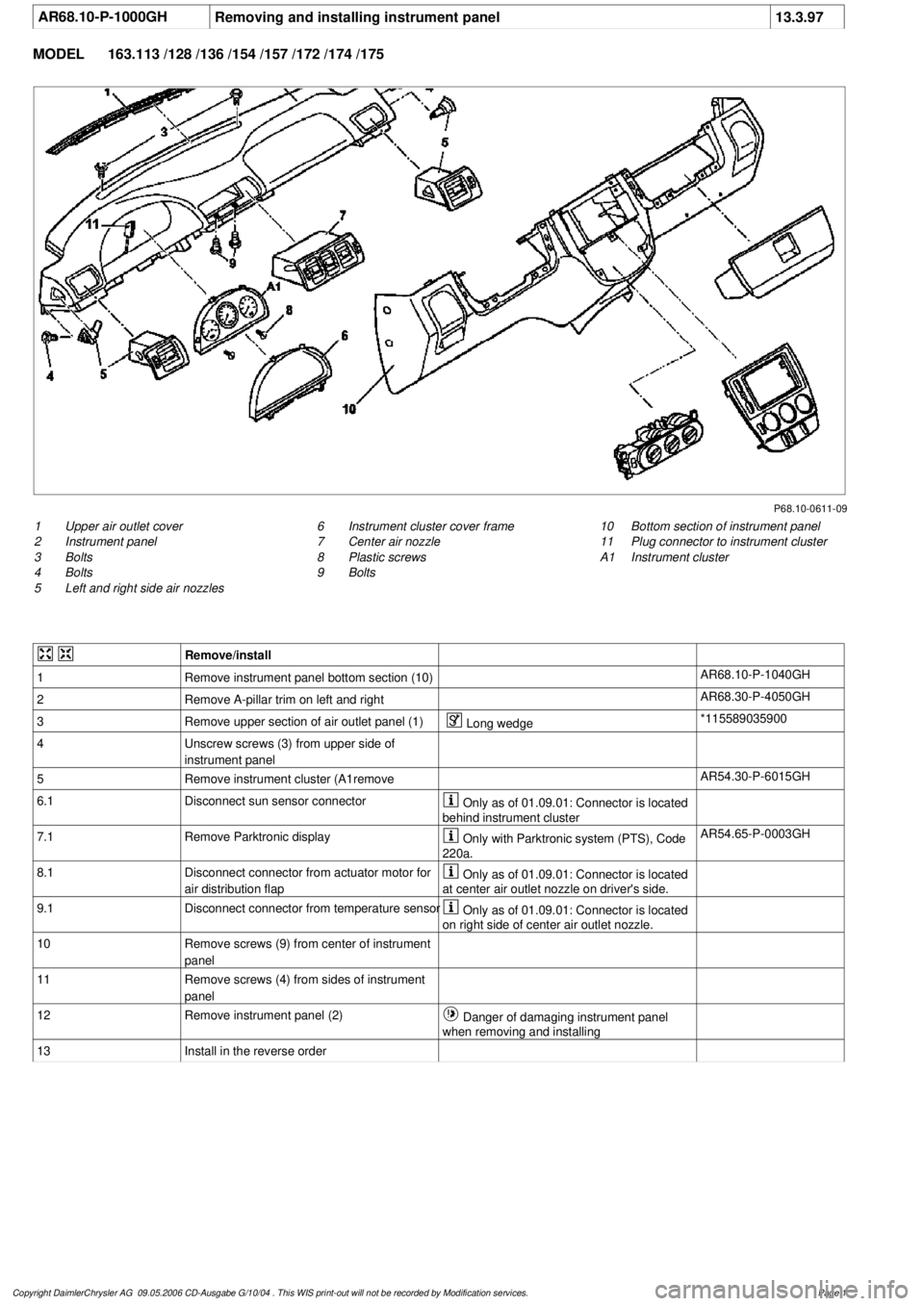
AR68.10-P-1000GH
Removing and installing instrument panel
13.3.97
MODEL
163.113 /128 /136 /154 /157 /172 /174 /175
P68.10-0611-09
1
Upper air outlet cover
2
Instrument panel
3
Bolts
4
Bolts
5
Left and right side air nozzles
10
Bottom section of instrument panel
11
Plug connector to instrument cluster
A1
Instrument cluster
6
Instrument cluster cover frame
7
Center air nozzle
8
Plastic screws
9
Bolts
Remove/install
1
Remove instrument panel bottom section (10)
AR68.10-P-1040GH
2
Remove A-pillar trim on left and right
AR68.30-P-4050GH
3
Remove upper section of air outlet panel (1)
Long wedge
*115589035900
4
Unscrew screws (3) from upper side of
instrument panel
5
Remove instrument cluster (A1remove
AR54.30-P-6015GH
6.1
Disconnect sun sensor connector
Only as of 01.09.01: Connector is located
behind instrument cluster
7.1
Remove Parktronic display
Only with Parktronic system (PTS), Code
220a.
AR54.65-P-0003GH
8.1
Disconnect connector from actuator motor for
air distribution flap
Only as of 01.09.01: Connector is located
at center air outlet nozzle on driver's side.
9.1
Disconnect connector from temperature sensor
Only as of 01.09.01: Connector is located
on right side of center air outlet nozzle.
10
Remove screws (9) from center of instrument
panel
11
Remove screws (4) from sides of instrument
panel
12
Remove instrument panel (2)
Danger of damaging instrument panel
when removing and installing
13
Install in the reverse order
Copyright DaimlerChrysler AG 09.05.2006 CD-Ausgabe G/10/04 . This WIS print-out will not be recorde
d by Modification services.
Page 1
Page 3518 of 4133
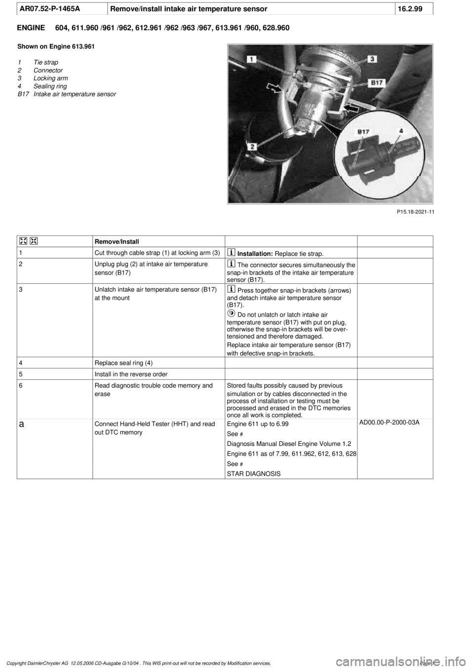
AR07.52-P-1465A
Remove/install intake air temperature sensor
16.2.99
ENGINE
604, 611.960 /961 /962, 612.961 /962 /963 /967, 613.961 /960, 628.960
P15.18-2021-11
Shown on Engine 613.961
1
Tie strap
2
Connector
3
Locking arm
4
Sealing ring
B17
Intake air temperature sensor
Remove/Install
1
Cut through cable strap (1) at locking arm (3)
Installation:
Replace tie strap.
2
Unplug plug (2) at intake air temperature
sensor (B17)
The connector secures simultaneously the
snap-in brackets of the intake air temperature
sensor (B17).
3
Unlatch intake air temperature sensor (B17)
at the mount
Press together snap-in brackets (arrows)
and detach intake air temperature sensor
(B17).
Do not unlatch or latch intake air
temperature sensor (B17) with put on plug,
otherwise the snap-in brackets will be over-
tensioned and therefore damaged.
Replace intake air temperature sensor (B17)
with defective snap-in brackets.
4
Replace seal ring (4)
5
Install in the reverse order
6
Read diagnostic trouble code memory and
erase
Stored faults possibly caused by previous
simulation or by cables disconnected in the
process of installation or testing must be
processed and erased in the DTC memories
once all work is completed.
a
Connect Hand-Held Tester (HHT) and read
out DTC memory
Engine 611 up to 6.99
See
#
AD00.00-P-2000-03A
Diagnosis Manual Diesel Engine Volume 1.2
Engine 611 as of 7.99, 611.962, 612, 613, 628
See
#
STAR DIAGNOSIS
Copyright DaimlerChrysler AG 12.05.2006 CD-Ausgabe G/10/04 . This WIS print-out will not be recorde
d by Modification services.
Page 1
Page 3523 of 4133
AUTOMATIC DIMMING INSIDE REARVIEW MIRROR, FUNCTION - GF68.49-P-0003GH
MODEL 163 as of 1.9.99 with CODE (249b) Automatic dimming inside rearview and outside rearview
mirror (driver)
Function requirements
No overvoltage or undervoltage
Term. 15R or 15 ON
Reverse gear not engaged
Interior lighting not switched on
Function
The glass of the inside rearview mirror (A67) can be electro-chromatically dimmed. The mirror glass between
the reflector and the glass cover contains a layer of electrolyte gel. The light transmission ratio of this gel
changes when a voltage is applied to it.
The light hitting the surface of the mirror is more or less reflected due to the variable of the actuation voltage.
The actuation voltage is controlled by the electronic circuitry in the inside rearview mirror. This is
accomplished depending on the ambient light and the light hitting the mirror.
The two input parameters are detected by the mirror dimming to rear sensor (A67h2) in the mirror housing
(rear) and by the mirror dimming forward sensor (A67h1) in the mirror glass of the inside rearview mirror
(A67).
The inside rearview mirror unit (A67) also acts as the master for the outside mirror dimming function
(driver's side).
CONTENTS - FUNCTION DESCRIPTION, AUTOMATIC DIMMING INSIDE REARVIEW MIRROR - GF68.49-P-0999GH
MODEL 163 as of 1.9.99 with CODE (249a) Automatic dimming inside rearview mirror
TROUBLE DIAGNOSIS
FRONT ASHTRAY DOES NOT OPEN SOFTLY OR IS STUCK - AF68.20-P-6000A
Garage door opener transmitter, location/ purpose GF68.05-P-1100A
Contents, function description of garage door opener GF68.05-P-0999A
Automatically dimming driver-side outside mirror, function GF88.79-P-2003GH
Function description, automatic dimming inside rearview mirror GF68.49-P-0003GH
Automatic dimming outside rearview mirror on driver's side, function GF88.79-P-2003GH
2001 Mercedes-Benz ML320
1998-2005 ACCESSORIES & BODY, CAB Interior Equipment - 163 Chassis
me
Saturday, October 02, 2010 3:35:21 PMPage 5 © 2006 Mitchell Repair Information Company, LLC.
Page 3534 of 4133
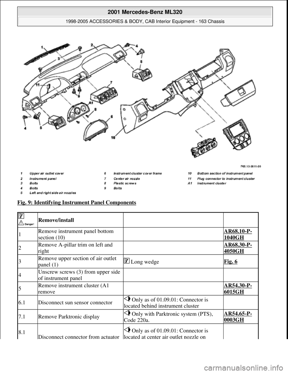
Fig. 9: Identifying Instrument Panel Components
Remove/install
1Remove instrument panel bottom
section (10) AR68.10-P-
1040GH
2Remove A-pillar trim on left and
right AR68.30-P-
4050GH
3Remove upper section of air outlet
panel (1) Long wedgeFig. 6
4Unscrew screws (3) from upper side
of instrument panel
5Remove instrument cluster (A1
remove AR54.30-P-
6015GH
6.1Disconnect sun sensor connector Only as of 01.09.01: Connector is
located behind instrument cluster
7.1Remove Parktronic display Only with Parktronic system (PTS),
Code 220a.AR54.65-P-
0003GH
8.1
Disconnect connector from actuator
Only as of 01.09.01: Connector is
located at center air outlet nozzle on
2001 Mercedes-Benz ML320
1998-2005 ACCESSORIES & BODY, CAB Interior Equipment - 163 Chassis
me
Saturday, October 02, 2010 3:35:21 PMPage 16 © 2006 Mitchell Repair Information Company, LLC.
Page 3535 of 4133
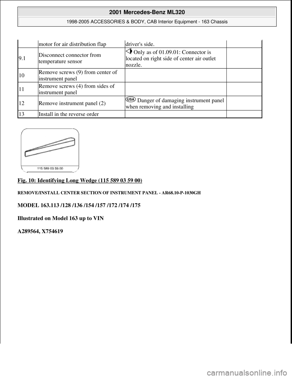
Fig. 10: Identifying Long Wedge (115 589 03 59 00)
REMOVE/INSTALL CENTER SECTION OF INSTRUMENT PANEL - AR68.10-P-1030GH
MODEL 163.113 /128 /136 /154 /157 /172 /174 /175
Illustrated on Model 163 up to VIN
A289564, X754619
motor for air distribution flapdriver's side.
9.1Disconnect connector from
temperature sensor Only as of 01.09.01: Connector is
located on right side of center air outlet
nozzle.
10Remove screws (9) from center of
instrument panel
11Remove screws (4) from sides of
instrument panel
12Remove instrument panel (2) Danger of damaging instrument panel
when removing and installing
13Install in the reverse order
2001 Mercedes-Benz ML320
1998-2005 ACCESSORIES & BODY, CAB Interior Equipment - 163 Chassis
me
Saturday, October 02, 2010 3:35:21 PMPage 17 © 2006 Mitchell Repair Information Company, LLC.
Page 3536 of 4133
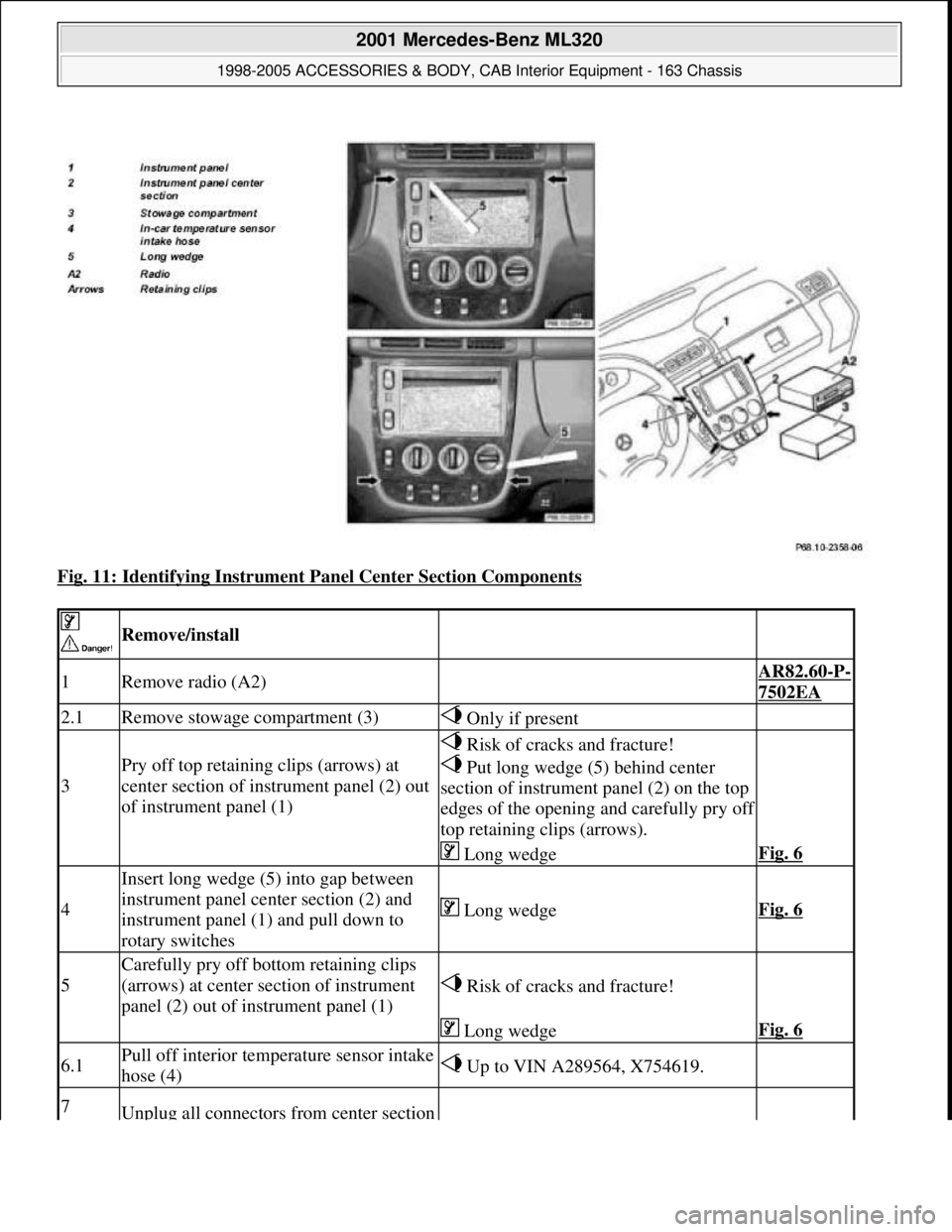
Fig. 11: Identifying Instrument Panel Center Section Components
Remove/install
1Remove radio (A2) AR82.60-P-
7502EA
2.1Remove stowage compartment (3) Only if present
3
Pry off top retaining clips (arrows) at
center section of instrument panel (2) out
of instrument panel (1)
Risk of cracks and fracture!
Put long wedge (5) behind center
section of instrument panel (2) on the top
edges of the opening and carefully pry off
top retaining clips (arrows).
Long wedgeFig. 6
4
Insert long wedge (5) into gap between
instrument panel center section (2) and
instrument panel (1) and pull down to
rotary switches
Long wedgeFig. 6
5
Carefully pry off bottom retaining clips
(arrows) at center section of instrument
panel (2) out of instrument panel (1)
Risk of cracks and fracture!
Long wedgeFig. 6
6.1Pull off interior temperature sensor intake
hose (4) Up to VIN A289564, X754619.
7Unplug all connectors from center section
2001 Mercedes-Benz ML320
1998-2005 ACCESSORIES & BODY, CAB Interior Equipment - 163 Chassis
me
Saturday, October 02, 2010 3:35:21 PMPage 18 © 2006 Mitchell Repair Information Company, LLC.