1997 MERCEDES-BENZ ML350 sensor
[x] Cancel search: sensorPage 3725 of 4133
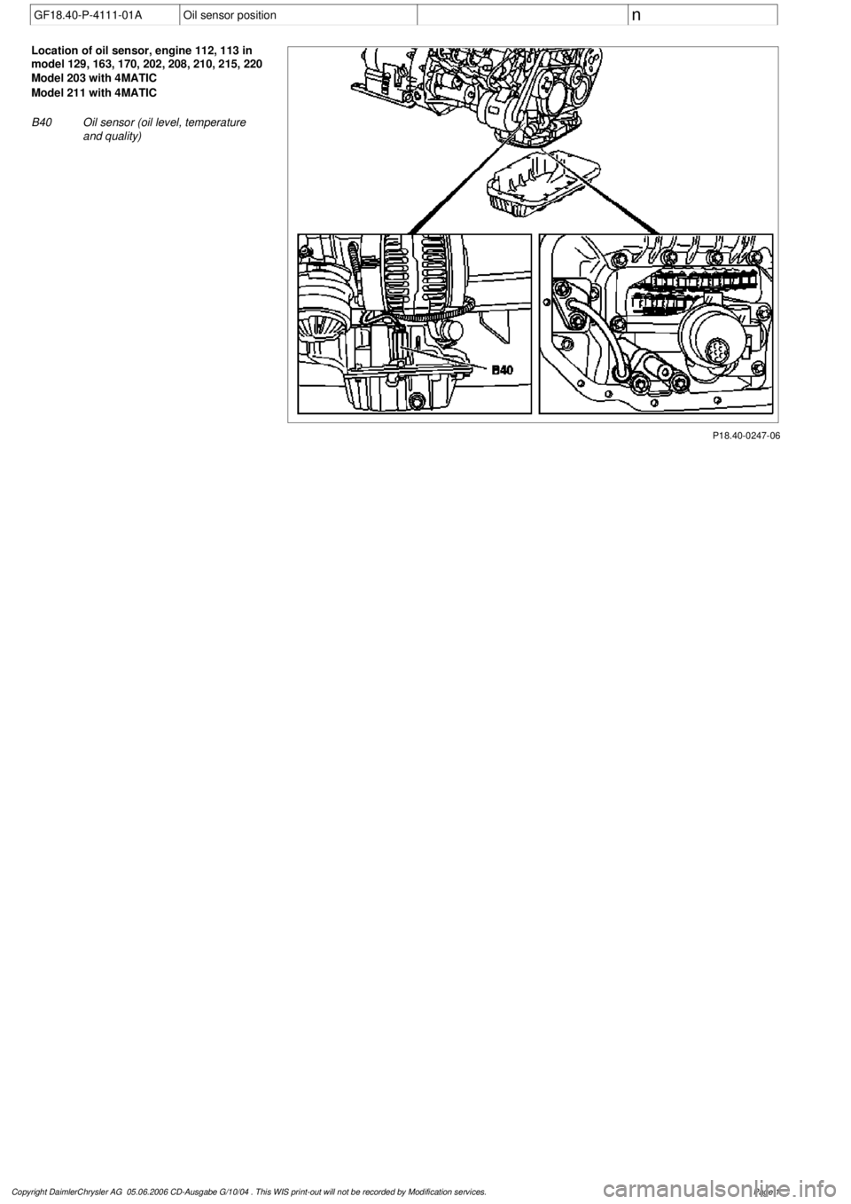
GF18.40-P-4111-01A
Oil sensor position
n
P18.40-0247-06
Location of oil sensor, engine 112, 113 in
model 129, 163, 170, 202, 208, 210, 215, 220
Model 203 with 4MATIC
Model 211 with 4MATIC
B40
Oil sensor (oil level, temperature
and quality)
Copyright DaimlerChrysler AG 05.06.2006 CD-Ausgabe G/10/04 . This WIS print-out will not be recorde
d by Modification services.
Page 1
Page 3734 of 4133

GF54.30-P-4104A
Outside temperature display, location/function
8.7.99
MODEL
129
MODEL
140 as of 1.6.96
MODEL
170
MODEL
163, 202 with CODE (240a) Outside temperature display
MODEL
202 as of 1.8.96
MODEL
168
MODEL
208 up to 31.7.99,
210 as of 1.6.96 up to 30.6.99
To display the temperature, the
outside temperature indicator
A1p4
requires:
D
the outside temperature
D
the speed signal
D
the engine running time
and
D
the coolant temperature (model 129, and model 140 as of
1.6.96, model 170, model 202 as of 08/96 and model 163,
model 168, model 210)
The outside temperature is determined by the outside temperature
indicator temperature sensor B14. The temperature sensor is
installed at the front left of the vehicle under the bumper and
connected to the instrument cluster A1 via the 21 or 25-pin
connector, coding part A terminal 1 and 2.
The speed signal, engine running time and engine temperature are
determined internally by the instrument cluster A1.
Since the outside temperature display depends on the speed, engine
running time and coolant temperature, high temperatures (influenced
by the heat generated by the engine, for example) are not displayed
when the vehicle is stationary or moving slowly.
Function, model 202 until 08/95
When the ignition is switched on and off and at speeds below approx.
20 km/h, the last temperature measured is stored and displayed.
If the measured outside temperature drops below the stored value,
the current measured temperature is displayed.
If the outside temperature rises above the stored value, the current
measured outside temperature is displayed only after the following
delays:
D
When the engine is not running, the current outside
temperature is only displayed after 6 times the engine running
time. For example, if the preceding running time was 5 minutes,
the current temperature is not displayed until after 30 minutes.
The maximum delay, however, is 1 hour.
Up to 09.94
D
At vehicle speeds between 20-60 km/h, outside temperatures
are displayed after a delay of approx. 5 min.
D
At vehicle speeds over 60 km/h, outside temperatures are
displayed after a delay of approx. 2 minutes.
As of 09.94
D
At vehicle speeds between 20-45 km/h, outside temperatures
are displayed after a delay of approx. 3 min.
D
At vehicle speeds over 45 km/h, outside temperatures are
displayed after a delay of approx. 1.5 min.
Function
Model 129, model 140 as of 1.6.96, model 170, model 202 as of
08/96, model 163, model 168, model 208 and model 210
D
When the ignition is turned on or off
and with an engine temperature < 60°C
the current temperature is always stored and displayed.
D
When the ignition is turned off
and with an engine temperature < 60°C
the temperature last measured is stored and displayed.
D
When the ignition is turned on
and when an engine temperature < 60(C
The stored temperature is displayed.
If the measured outside temperature drops below the stored value,
the current measured temperature is displayed.
If the outside temperature rises above the stored value, the current
measured outside temperature is displayed only after the following
delays:
D
When the engine is not running, the current outside
temperature is only displayed after 6 times the engine running
time. For example, if the preceding running time was 5 minutes,
the current temperature is not displayed until after 30 minutes.
The maximum delay, however, is 1 hour.
D
At vehicle speeds between 20-45 km/h, outside temperatures
are displayed after a delay of approx. 3 minutes.
D
At vehicle speeds above 45 km/h, outside temperatures are
displayed after a delay of approx. 1.5 minutes.
Copyright DaimlerChrysler AG 05.06.2006 CD-Ausgabe G/10/04 . This WIS print-out will not be recorde
d by Modification services.
Page 1
Page 3737 of 4133
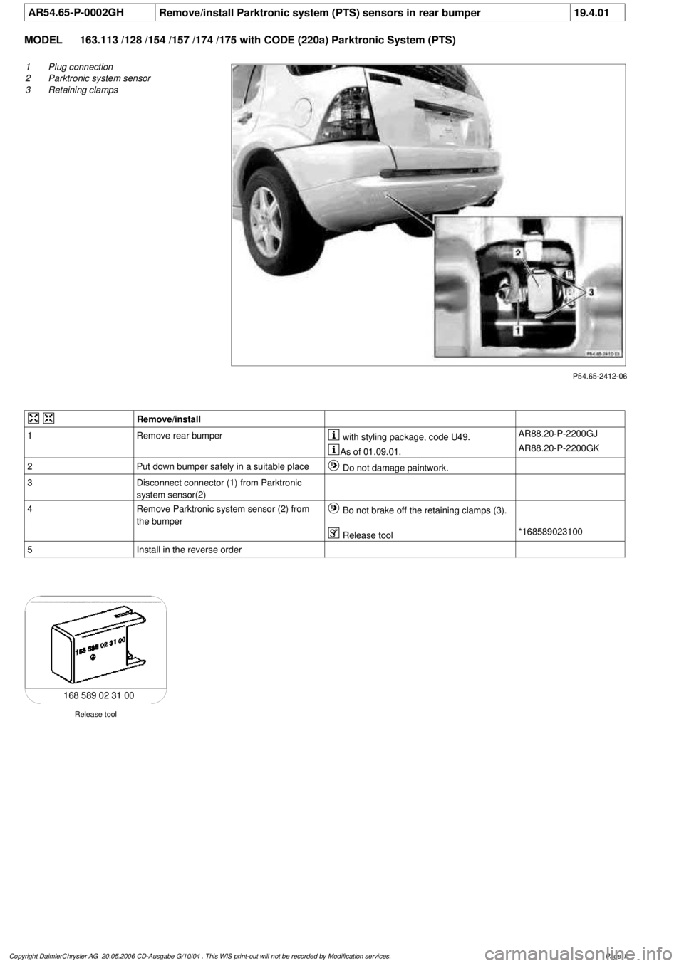
AR54.65-P-0002GH
Remove/install Parktronic system (PTS) sensors in rear bumper
19.4.01
MODEL
163.113 /128 /154 /157 /174 /175 with CODE (220a) Parktronic System (PTS)
P54.65-2412-06
1
Plug connection
2
Parktronic system sensor
3
Retaining clamps
Remove/install
1
Remove rear bumper
with styling package, code U49.
AR88.20-P-2200GJ
As of 01.09.01.
AR88.20-P-2200GK
2
Put down bumper safely in a suitable place
Do not damage paintwork.
3
Disconnect connector (1) from Parktronic
system sensor(2)
4
Remove Parktronic system sensor (2) from
the bumper
Bo not brake off the retaining clamps (3).
Release tool
*168589023100
5
Install in the reverse order
Release tool
168 589 02 31 00
Copyright DaimlerChrysler AG 20.05.2006 CD-Ausgabe G/10/04 . This WIS print-out will not be recorde
d by Modification services.
Page 1
Page 3751 of 4133

GF54.30-P-3017A
Quartz, location/task/function
8.7.99
MODEL
129, 140 as of 1.6.96,
163, 168, 170,
202 as of 1.8.96,
208,
210 as of 1.6.96,
215, 220
P54.30-0519-01
Piezo-electric effect:
A thin quartz plate (c) is coated on two opposing sides with a conductive material (a), (b) (see
illustration). If a tensile or compressive load is applied to the array, an electrical voltage "U" i
s
produced between the points (d) and (e). The polarity of the generated voltage depends on the
direction of load (compression/tension).
Reversed piezo-electric effect:
If, however, a voltage is applied to the points (d) and (e), the quartz plate increases or decreases
in length.
Task:
Mechanical vibrations can be converted into electrical oscillations using the piezo-electric effect.
For example, for microphones, knock sensors, pressure sensors.
Electrical oscillations can be converted into mechanical vibrations or motion using the reversed
piezo-electric effect: piezo-electric speakers, actuators.
Both effects are combined in the quartz resonator: If an AC voltage whose frequency is roughly
equal to the mechanical resonant frequency (fundamental or harmonic component) of the quartz
plate is applied to the points (d) and (e), the quartz is stimulated to generate resonant vibrations
which stabilize the frequency of the electrical oscillations. For this reason, quartz resonators are
often used where a high degree of frequency stability is required (e.g. in clock generators
(oscillators) for electronic clocks and microprocessors).
Copyright DaimlerChrysler AG 05.06.2006 CD-Ausgabe G/10/04 . This WIS print-out will not be recorde
d by Modification services.
Page 1
Page 3777 of 4133
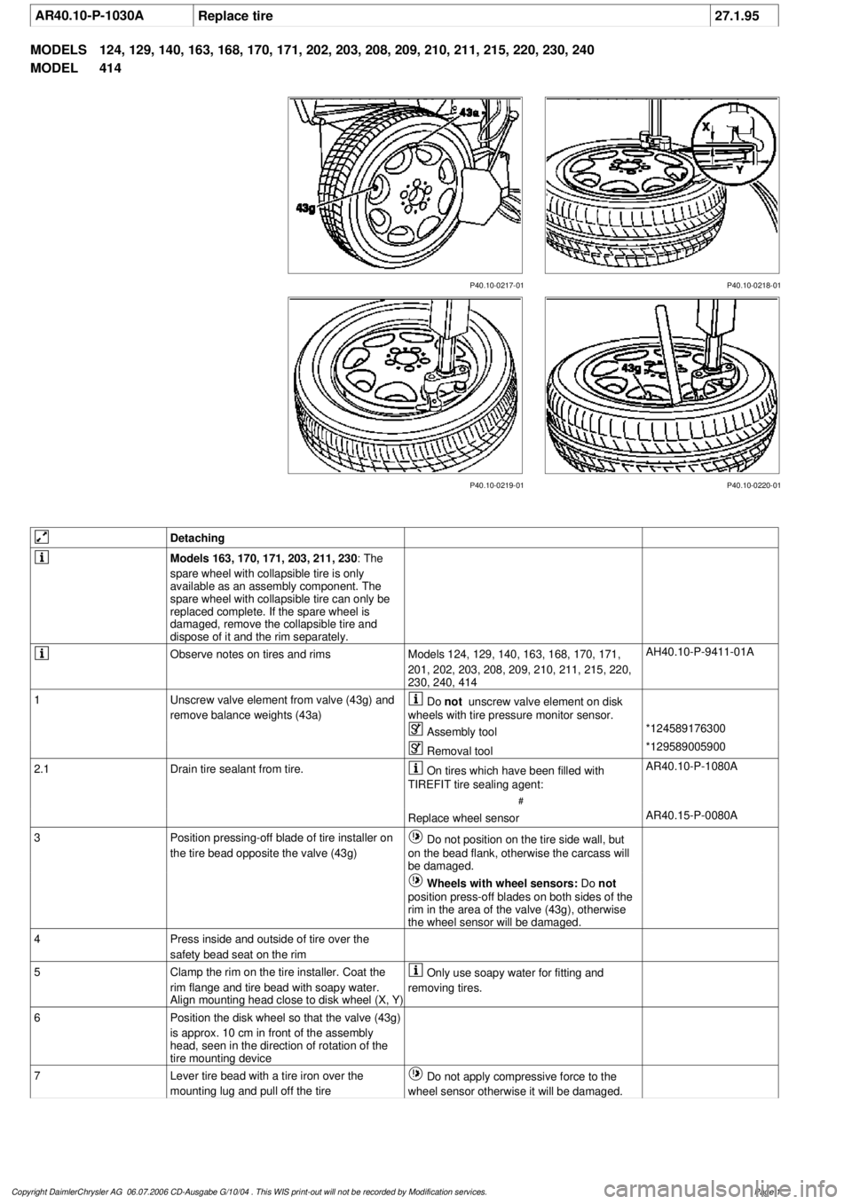
AR40.10-P-1030A
Replace tire
27.1.95
MODELS
124, 129, 140, 163, 168, 170, 171, 202, 203, 208, 209, 210, 211, 215, 220, 230, 240
MODEL
414
P40.10-0218-01
P40.10-0217-01
P40.10-0219-01 P40.10-0220-01
Detaching
Models 163, 170, 171, 203, 211, 230
: The
spare wheel with collapsible tire is only
available as an assembly component. The
spare wheel with collapsible tire can only be
replaced complete. If the spare wheel is
damaged, remove the collapsible tire and
dispose of it and the rim separately.
Observe notes on tires and rims
Models 124, 129, 140, 163, 168, 170, 171,
201, 202, 203, 208, 209, 210, 211, 215, 220,
230, 240, 414
AH40.10-P-9411-01A
1
Unscrew valve element from valve (43g) and
remove balance weights (43a)
Do
not
unscrew valve element on disk
wheels with tire pressure monitor sensor.
Assembly tool
*124589176300
Removal tool
*129589005900
2.1
Drain tire sealant from tire.
On tires which have been filled with
TIREFIT tire sealing agent:
#
AR40.10-P-1080A
Replace wheel sensor
AR40.15-P-0080A
3
Position pressing-off blade of tire installer on
the tire bead opposite the valve (43g)
Do not position on the tire side wall, but
on the bead flank, otherwise the carcass will
be damaged.
Wheels with wheel sensors:
Do
not
position press-off blades on both sides of the
rim in the area of the valve (43g), otherwise
the wheel sensor will be damaged.
4
Press inside and outside of tire over the
safety bead seat on the rim
5
Clamp the rim on the tire installer. Coat the
rim flange and tire bead with soapy water.
Align mounting head close to disk wheel (X, Y)
Only use soapy water for fitting and
removing tires.
6
Position the disk wheel so that the valve (43g)
is approx. 10 cm in front of the assembly
head, seen in the direction of rotation of the
tire mounting device
7
Lever tire bead with a tire iron over the
mounting lug and pull off the tire
Do not apply compressive force to the
wheel sensor otherwise it will be damaged.
Copyright DaimlerChrysler AG 06.07.2006 CD-Ausgabe G/10/04 . This WIS print-out will not be recorde
d by Modification services.
Page 1
Page 3778 of 4133
8.1
Check wheel sensor, valve body and sealing
rubber for damage
Vehicles with tire pressure monitor (code 475)
Do not remove wheel sensor for this.
Do not use compressed air, solvents or
detergents to clean the wheel sensor. Wipe
off dirt with a clean, lint-free cloth only.
Do not retighten the female torx bolt and
union nut.
Replace all valve components of wheel
electronics if:
D
The wheel sensor mounting bolt or union
nut is visibly loose.
Replace the wheel sensor if:
D
The wheel sensor is obviously damaged.
D
Tire sealant was used.
Install new wheel sensors:
#
Replace wheel sensor.
AR40.15-P-0080A
8.2
Install new valve (43g).
Vehicles without tire pressure monitor (code
475)
9
Checking condition of rim
AR40.10-P-1010-01A
Mounting
10
Moisten rim flange and tire beads with soapy
water and align assembly head at a small
distance (X, Y) to the disk wheel
Only use soapy water for fitting and
removing tires.
11
Place tire obliquely on the rim and pull on
over the rim flange using the tire installer
Position wheels with wheel sensors so
that the wheel sensor is approximately 180°
opposite the mounting head.
Do not apply compressive force to the wheel
sensor otherwise it will be damaged.
Observe the running direction on tires with
specified running direction.
Put as little stress as possible on bead
area.
12
Align the match points of the tire and disk
wheel with each other and remove the disk
wheel with tire from the tire mounting device
13
Inflate tires without valve element up to max.
3 bar
Do
not
unscrew valve element on disk
wheels with tire pressure monitor sensor.
The tire must slide evenly over the safety
shoulders of the disk wheel, otherwise coat
the tire beads with soapy water again.
14
Screw the valve element into the valve (43g)
and adjust the tire inflation pressure to the
specified value
Observe the tire pressure information in
the fuel filler flap of the vehicle.
15
Balance wheel
AR40.10-P-1040A
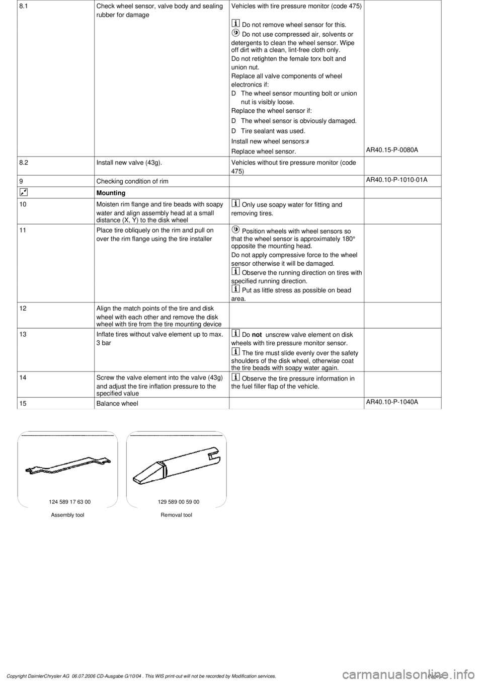
124 589 17 63 00 129 589 00 59 00
Removal tool
Assembly tool
Copyright DaimlerChrysler AG 06.07.2006 CD-Ausgabe G/10/04 . This WIS print-out will not be recorde
d by Modification services.
Page 2
Page 3843 of 4133
The opening angle of the throttle valve will only be determined by the accelerator pedal specification when no
limiting functions are active.
The accelerator pedal position is detected by the set value potentiometer (B37r1) or Hall sensor in the pedal
value sensor (B37) and information is released to the ME control unit (N3/10). In this way, the ME-SFI control
unit determines the position of the throttle valve and actuates the throttle valve motor (M16/1 m1).
The actual value potentiometer in the actuator (M16/1r1) signals the throttle valve position back to the ME-SFI
control unit.
The second potentiometer in the actuator (M16/1 r2) and the second signal from the pedal value sensor
(potentiometer or Hall sensor) supplies a reference value for the plausibility check. In addition, the system
switches over to the second potentiometer or the Hall sensor if the first potentiometer or Hall sensor fails
(emergency mode).
Adaptive accelerator pedal (model 203, 209, 211, 215, 220, 230):
The engine control unit recognizes how the accelerator pedal is being actuated and switches between
characteristic curves. Eighty percent of the engine load is released for a pedal travel of about 50 % for a sporty
driver and about 40 % for a quiet driver. There is no further difference felt above a pedal travel of about 90 %.
If, for example, the characteristic curve for a quiet driver is active after a long drive on the motorway then the
accelerator pedal must be pressed down unusually hard to obtain a higher acceleration level.
Kickdown switch (S16/6)
The kickdown switch was no longer used from 9/01. Recognition of full load is now achieved over the signal
from the pedal value sensor. The pressure point on the accelerator pedal before achieving the full load position
remains.
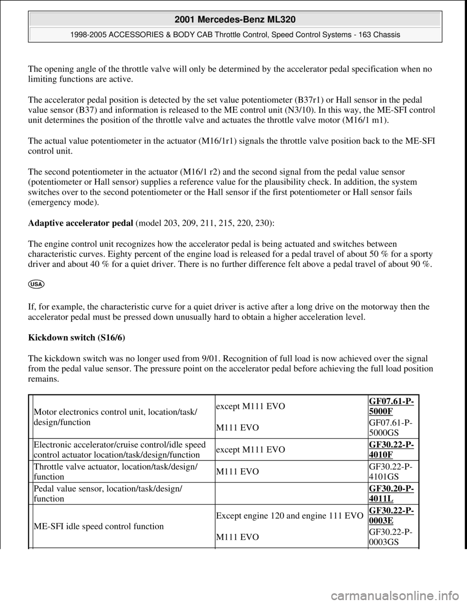
Motor electronics control unit, location/task/
design/functionexcept M111 EVOGF07.61-P-
5000F
M111 EVOGF07.61-P-
5000GS
Electronic accelerator/cruise control/idle speed
control actuator location/task/design/functionexcept M111 EVOGF30.22-P-
4010F
Throttle valve actuator, location/task/design/
functionM111 EVOGF30.22-P-
4101GS
Pedal value sensor, location/task/design/
function GF30.20-P-
4011L
ME-SFI idle speed control function
Except engine 120 and engine 111 EVOGF30.22-P-
0003E
M111 EVOGF30.22-P-
0003GS
2001 Mercedes-Benz ML320
1998-2005 ACCESSORIES & BODY CAB Throttle Control, Speed Control Systems - 163 Chassis
me
Saturday, October 02, 2010 3:36:27 PMPage 3 © 2006 Mitchell Repair Information Company, LLC.
Page 3844 of 4133
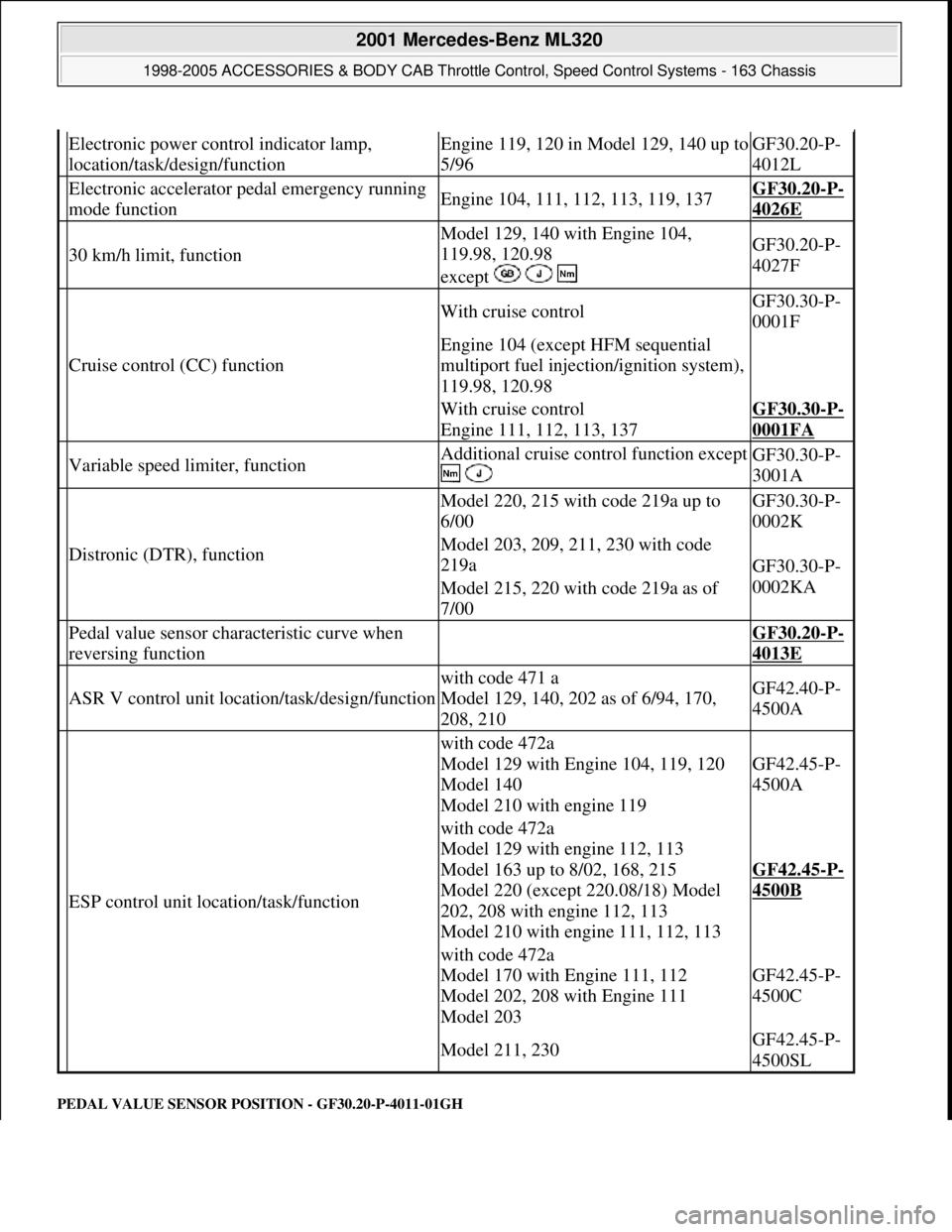
PEDAL VALUE SENSOR PO SITION - GF30.20-P-4011-01GH
Electronic power control indicator lamp,
location/task/design/functionEngine 119, 120 in Model 129, 140 up to
5/96GF30.20-P-
4012L
Electronic accelerator pe dal emergency running
mode functionEngine 104, 111, 112, 113, 119, 137GF30.20-P-
4026E
30 km/h limit, function
Model 129, 140 with Engine 104,
119.98, 120.98
except GF30.20-P-
4027F
Cruise control (CC) function
With cruise controlGF30.30-P-
0001F
Engine 104 (except HFM sequential
multiport fuel injection/ignition system),
119.98, 120.98
With cruise control
Engine 111, 112, 113, 137GF30.30-P-
0001FA
Variable speed limiter, functionAdditional cruise control function except
GF30.30-P-
3001A
Distronic (DTR), function
Model 220, 215 with code 219a up to
6/00GF30.30-P-
0002K
Model 203, 209, 211, 230 with code
219a
GF30.30-P-
0002KA
Model 215, 220 with code 219a as of
7/00
Pedal value sensor characteristic curve when
reversing function GF30.20-P-
4013E
ASR V control unit location/task/design/function
with code 471 a
Model 129, 140, 202 as of 6/94, 170,
208, 210GF42.40-P-
4500A
ESP control unit location/task/function
with code 472a
Model 129 with Engine 104, 119, 120
Model 140
Model 210 with engine 119
GF42.45-P-
4500A
with code 472a
Model 129 with engine 112, 113
Model 163 up to 8/02, 168, 215
Model 220 (except 220.08/18) Model
202, 208 with engine 112, 113
Model 210 with engine 111, 112, 113
GF42.45-P-
4500B
with code 472a
Model 170 with Engine 111, 112
Model 202, 208 with Engine 111
Model 203
GF42.45-P-
4500C
Model 211, 230GF42.45-P-
4500SL
2001 Mercedes-Benz ML320
1998-2005 ACCESSORIES & BODY CAB Throttle Control, Speed Control Systems - 163 Chassis
me
Saturday, October 02, 2010 3:36:27 PMPage 4 © 2006 Mitchell Repair Information Company, LLC.