Page 3855 of 4133
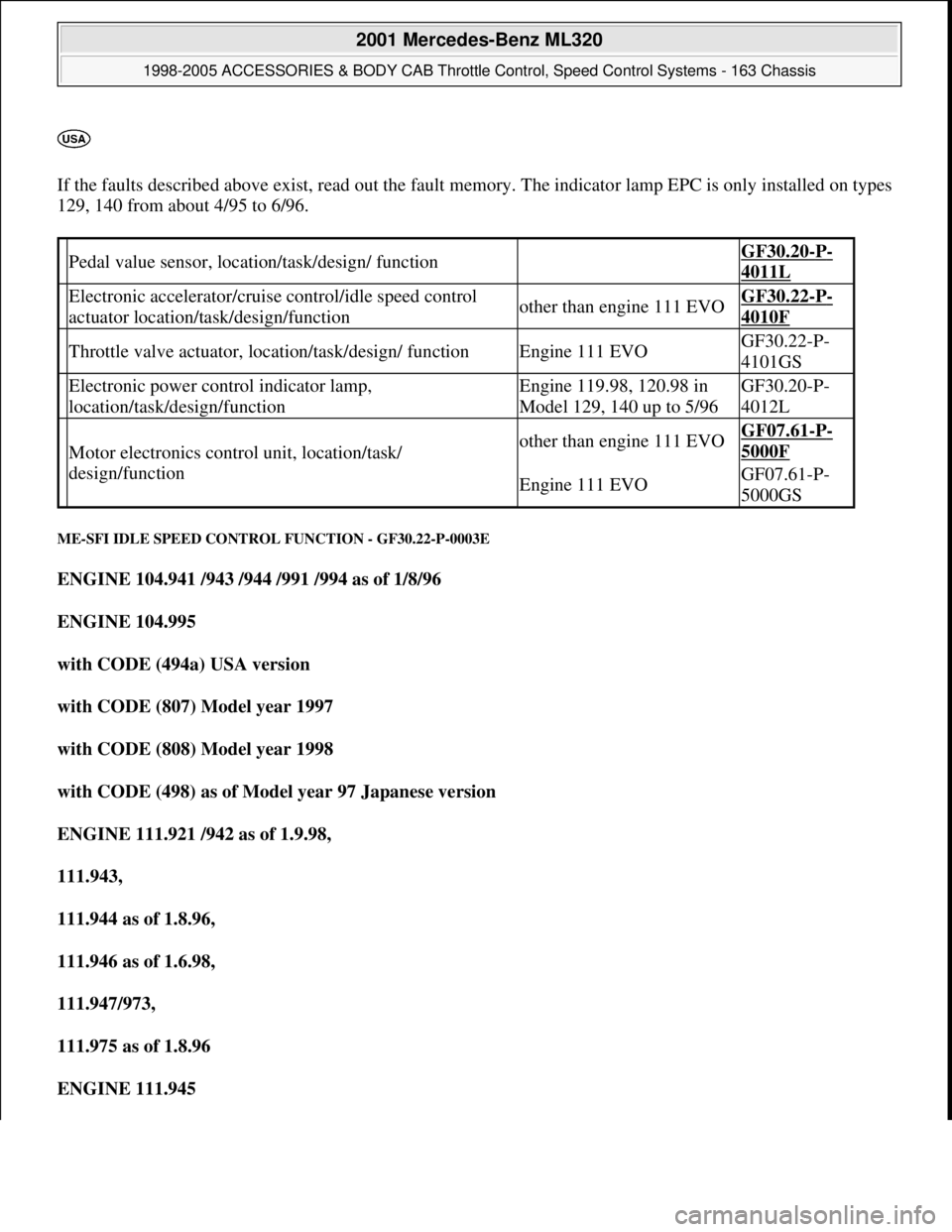
If the faults described above exist, read out the fault memory. The indicator lamp EPC is only installed on types
129, 140 from about 4/95 to 6/96.
ME-SFI IDLE SPEED CONTROL FUNCTION - GF30.22-P-0003E
ENGINE 104.941 /943 /944 /991 /994 as of 1/8/96
ENGINE 104.995
with CODE (494a) USA version
with CODE (807) Model year 1997
with CODE (808) Model year 1998
with CODE (498) as of Model year 97 Japanese version
ENGINE 111.921 /942 as of 1.9.98,
111.943,
111.944 as of 1.8.96,
111.946 as of 1.6.98,
111.947/973,
111.975 as of 1.8.96
ENGINE 111.945
Pedal value sensor, location/task/design/ function GF30.20-P-
4011L
Electronic accelerator/cruise control/idle speed control
actuator location/task/design/functionother than engine 111 EVOGF30.22-P-
4010F
Throttle valve actuator, location/task/design/ functionEngine 111 EVOGF30.22-P-
4101GS
Electronic power control indicator lamp,
location/task/design/functionEngine 119.98, 120.98 in
Model 129, 140 up to 5/96GF30.20-P-
4012L
Motor electronics control unit, location/task/
design/functionother than engine 111 EVOGF07.61-P-
5000F
Engine 111 EVOGF07.61-P-
5000GS
2001 Mercedes-Benz ML320
1998-2005 ACCESSORIES & BODY CAB Throttle Control, Speed Control Systems - 163 Chassis
me
Saturday, October 02, 2010 3:36:27 PMPage 15 © 2006 Mitchell Repair Information Company, LLC.
Page 3858 of 4133
vehicles delivered from 6/00 is increased for the driving mode selected by about 100 rpm when the switch-on
threshold of about 900 rpm is exceeded. This increase is cancelled again when the external temperature drops
below 32° C.
Undervoltage
If the engine control unit detects an undervoltage the idling speed is increased until the ignition is switched off
for the driving mode selected by about 100 rpm.
If the control unit SBC reports an undervoltage to the engine control unit over CAN the idling speed for the
driving mode selected is increased to about 750 rpm.
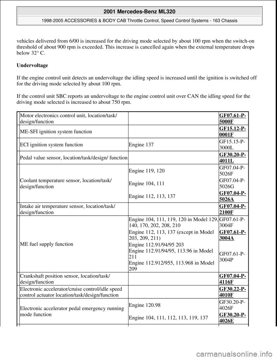
Motor electronics control unit, location/task/
design/function GF07.61-P-
5000F
ME-SFI ignition system function GF15.12-P-
0001F
ECI ignition system functionEngine 137GF15.15-P-
3000L
Pedal value sensor, location/task/design/ function GF30.20-P-
4011L
Coolant temperature sensor, location/task/
design/function
Engine 119, 120GF07.04-P-
5026F
Engine 104, 111GF07.04-P-
5026G
Engine 112, 113, 137GF07.04-P-
5026A
Intake air temperature sensor, location/task/
design/function GF07.04-P-
2100F
ME fuel supply function
Engine 104, 111, 119, 120 in Model 129,
140, 170, 202, 208, 210GF07.61-P-
3004F
Engine 112, 113, 137 (except in Model
203, 209, 211)GF07.61-P-
3004A
Engine 112.91/94/95 203
Engine 112.91/94/95, 113.96 in Model
211
Engine 112.912/955, 113.968 in Model
209
GF07.61-P-
3004P
Crankshaft position sensor, location/task/
design/function GF07.04-P-
4116F
Electronic accelerator/cruise control/idle speed
control actuator location/task/design/function GF30.22-P-
4010F
Electronic accelerator pedal emergency running
mode functionEngine 120.98GF30.20-P-
4026F
Engine 104, 111, 112, 113, 119, 137GF30.20-P-
4026E
2001 Mercedes-Benz ML320
1998-2005 ACCESSORIES & BODY CAB Throttle Control, Speed Control Systems - 163 Chassis
me
Saturday, October 02, 2010 3:36:27 PMPage 18 © 2006 Mitchell Repair Information Company, LLC.
Page 3862 of 4133
If the actuator is de-energized, the throttle valve is resting against the spring capsule. As a result the
throttle valve opening is constantly approx. 10 to 12 °. The engine speed for the no load condition is
about 1800 rpm.
D.Driving mode
The actuating motor when driving (partial/full load) regulates the throttle valve according to the various
loading conditions or according to the input signals from the front pedal value sensor (B37) according to
the position of the accelerator pedal.
E.Throttle valve damping
A damping function for the throttle valve is integrated in the ME control unit. In case of a sudden release of the
accelerator, the throttle valve in the idle speed range is closed with delay.
When first connecting to terminal 30 the ME control unit independently undertakes adaptation of the actuator
(learn the lower mechanical limit stop and full-load position of the throttle valve).
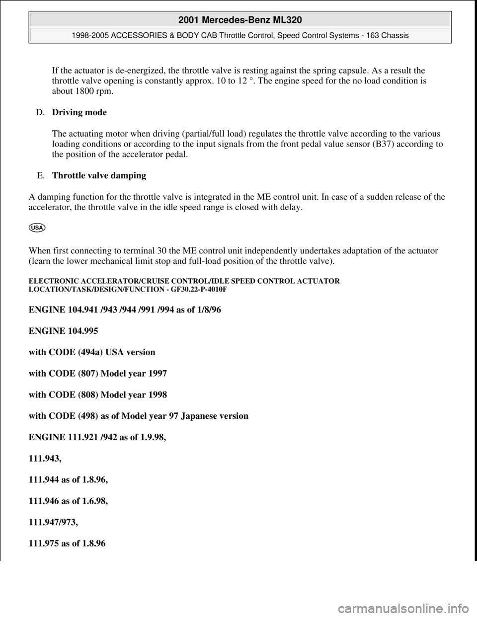
ELECTRONIC ACCELERATOR/CRUISE CONTROL/IDLE SPEED CONTROL ACTUATOR
LOCATION/TASK/DESIGN/FUNCTION - GF30.22-P-4010F
ENGINE 104.941 /943 /944 /991 /994 as of 1/8/96
ENGINE 104.995
with CODE (494a) USA version
with CODE (807) Model year 1997
with CODE (808) Model year 1998
with CODE (498) as of Model year 97 Japanese version
ENGINE 111.921 /942 as of 1.9.98,
111.943,
111.944 as of 1.8.96,
111.946 as of 1.6.98,
111.947/973,
111.975 as of 1.8.96
2001 Mercedes-Benz ML320
1998-2005 ACCESSORIES & BODY CAB Throttle Control, Speed Control Systems - 163 Chassis
me
Saturday, October 02, 2010 3:36:27 PMPage 22 © 2006 Mitchell Repair Information Company, LLC.
Page 3870 of 4133
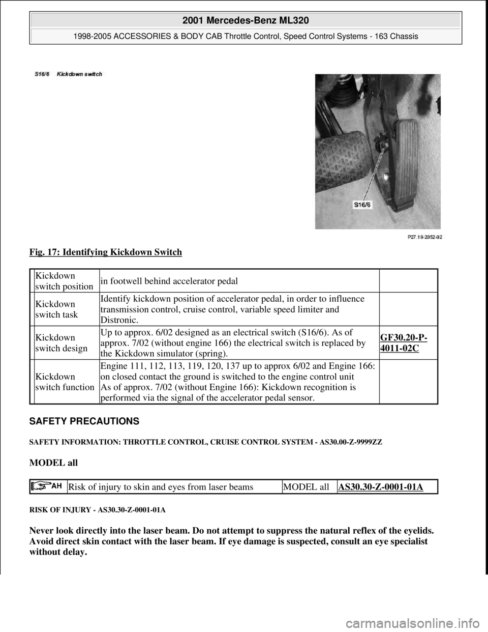
Fig. 17: Identifying Kickdown Switch
SAFETY PRECAUTIONS
SAFETY INFORMATION: THROTTLE CONTROL, CRUISE CONTROL SYSTEM - AS30.00-Z-9999ZZ
MODEL all
RISK OF INJURY - AS30.30-Z-0001-01A
Never look directly into the laser beam. Do not attempt to suppress the natural reflex of the eyelids.
Avoid direct skin contact with the laser beam. If eye damage is suspected, consult an eye specialist
without delay.
Kickdown
switch positionin footwell behind accelerator pedal
Kickdown
switch taskIdentify kickdown position of accelerator pedal, in order to influence
transmission control, cruise control, variable speed limiter and
Distronic.
Kickdown
switch designUp to approx. 6/02 designed as an electrical switch (S16/6). As of
approx. 7/02 (without engine 166) the electrical switch is replaced by
the Kickdown simulator (spring).GF30.20-P-
4011-02C
Kickdown
switch function
Engine 111, 112, 113, 119, 120, 137 up to approx 6/02 and Engine 166:
on closed contact the ground is switched to the engine control unit
As of approx. 7/02 (without Engine 166): Kickdown recognition is
performed via the signal of the accelerator pedal sensor.
Risk of injury to skin and eyes from laser beamsMODEL allAS30.30-Z-0001-01A
2001 Mercedes-Benz ML320
1998-2005 ACCESSORIES & BODY CAB Throttle Control, Speed Control Systems - 163 Chassis
me
Saturday, October 02, 2010 3:36:27 PMPage 30 © 2006 Mitchell Repair Information Company, LLC.
Page 3872 of 4133
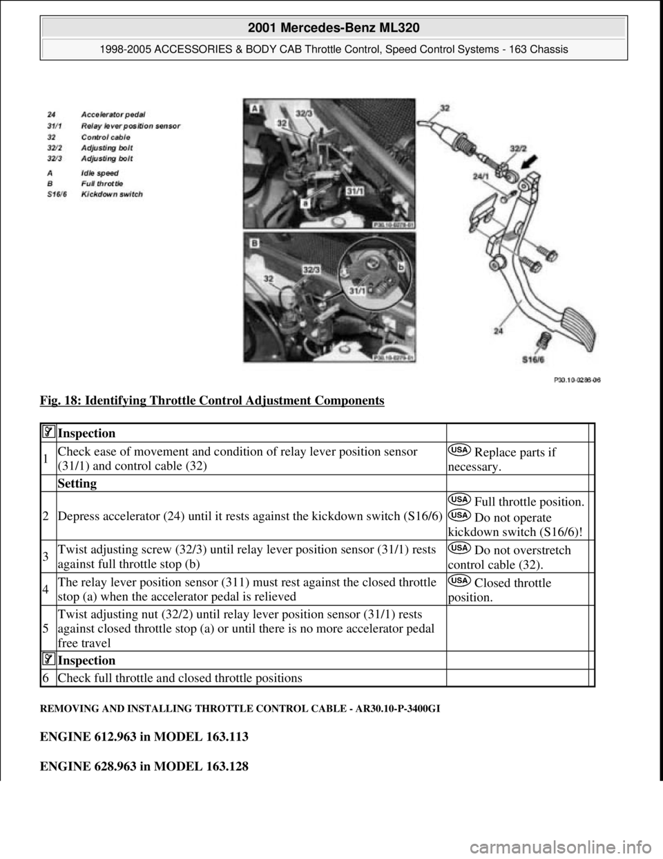
Fig. 18: Identifying Throttle Control Adjustment Components
REMOVING AND INSTALLING THROTTLE CONTROL CABLE - AR30.10-P-3400GI
ENGINE 612.963 in MODEL 163.113
ENGINE 628.963 in MODEL 163.128
Inspection
1Check ease of movement and condition of relay lever position sensor
(31/1) and control cable (32) Replace parts if
necessary.
Setting
2Depress accelerator (24) until it rests against the kickdown switch (S16/6)
Full throttle position.
Do not operate
kickdown switch (S16/6)!
3Twist adjusting screw (32/3) until relay lever position sensor (31/1) rests
against full throttle stop (b) Do not overstretch
control cable (32).
4The relay lever position sensor (311) must rest against the closed throttle
stop (a) when the accelerator pedal is relieved Closed throttle
position.
5
Twist adjusting nut (32/2) until relay lever position sensor (31/1) rests
against closed throttle stop (a) or until there is no more accelerator pedal
free travel
Inspection
6Check full throttle and closed throttle positions
2001 Mercedes-Benz ML320
1998-2005 ACCESSORIES & BODY CAB Throttle Control, Speed Control Systems - 163 Chassis
me
Saturday, October 02, 2010 3:36:28 PMPage 32 © 2006 Mitchell Repair Information Company, LLC.
Page 3875 of 4133
Fig. 20: Identifying Accelerator Pedal Components
REMOVE/INSTALL ELECTRONIC ACCELERATOR ACTUATOR WITH FLAP CONNECTION - AR30.20-P-1262A
MODEL 129, 163, 170, 171, 202, 203, 208, 209, 210, 215, 220, 230, 463 (except, 215.376 /378 /379,
220.176 /876 /178 /878 /179, 230.476 /477 /479)
Mass air flow sensor removed
Shown on engine 112 in model 210
Remove, Install
1Detach control cable (30) at accelerator pedal
(24) (arrow) Pull out expanding wedge bolt (24/1) in
order to do this.
2Unscrew screws (34/2) from accelerator pedal
(24)
3Remove accelerator pedal (24)
4Install in the reverse order
2001 Mercedes-Benz ML320
1998-2005 ACCESSORIES & BODY CAB Throttle Control, Speed Control Systems - 163 Chassis
me
Saturday, October 02, 2010 3:36:28 PMPage 35 © 2006 Mitchell Repair Information Company, LLC.
Page 3885 of 4133
Fig. 1: Disconnecting Negative Battery Cable
Courtesy of MERCEDES-BENZ OF NORTH AMERICA.
BASIC PROGRAMMING
1. Code radio. See Coding radio .
2. Set time on instrument cluster. Pull out knob at lowe r right of speedometer. To adjust hour, turn to right.
To adjust minute, turn to left.
3. If necessary, set time at stationary heater timer. See owner's manual.
4. Start engine and run at idle. Turn steering wheel fr om one lock position to the other to activate steering
angle sensor. Center steering wheel. Ma lfunction indicator lamp should go out.
5. If equipped, normalize ti lting/sliding roof. Open sunroof and hold down switch. Sunroof moves to end
position and pulls back 1/4 turn and stops. If equipped with lemella slidin
g roof, close roof and keep
2001 Mercedes-Benz ML320
2001-04 STARTING & CHARGING SYSTEMS Starters - 163 Chassis
me
Saturday, October 02, 2010 3:19:47 PMPage 3 © 2006 Mitchell Repair Information Company, LLC.
Page 3954 of 4133
GF54.50-P-4100-02GH
Trip computer control module, design
n
The trip computer control module (TRIP, N41) consists of the
following components:
D
Electronics unit
D
LCD display
D
Reset button (left button, N41s1)
D
Mode button (right button, N41s2)
D
Inclination sensor (N41b1)
D
Glass breakage sensor (N41b2)
D
CAN interface
D
Alarm bus to all activity module (AAM, N10)
D
as of 1.9.00: Interface (RS 485) to electronic compass (B26)
Copyright DaimlerChrysler AG 18.05.2006 CD-Ausgabe G/10/04 . This WIS print-out will not be recorde
d by Modification services.
Page 1