Page 3845 of 4133
Model 163
in left of component compartment
Fig. 2: Locating Pedal Valu e Sensor (Hall Principle)
PEDAL VALUE SENSOR DE SIGN - GF30.20-P-4011-02B
with two Hall elements
Fig. 3: Identifying Pedal Value Sensor (With Hall Principle)
Illustration shows internal circuitry of pedal value sensor B37 (with Hall principle)
2001 Mercedes-Benz ML320
1998-2005 ACCESSORIES & BODY CAB Throttle Control, Speed Control Systems - 163 Chassis
me
Saturday, October 02, 2010 3:36:27 PMPage 5 © 2006 Mitchell Repair Information Company, LLC.
Page 3846 of 4133
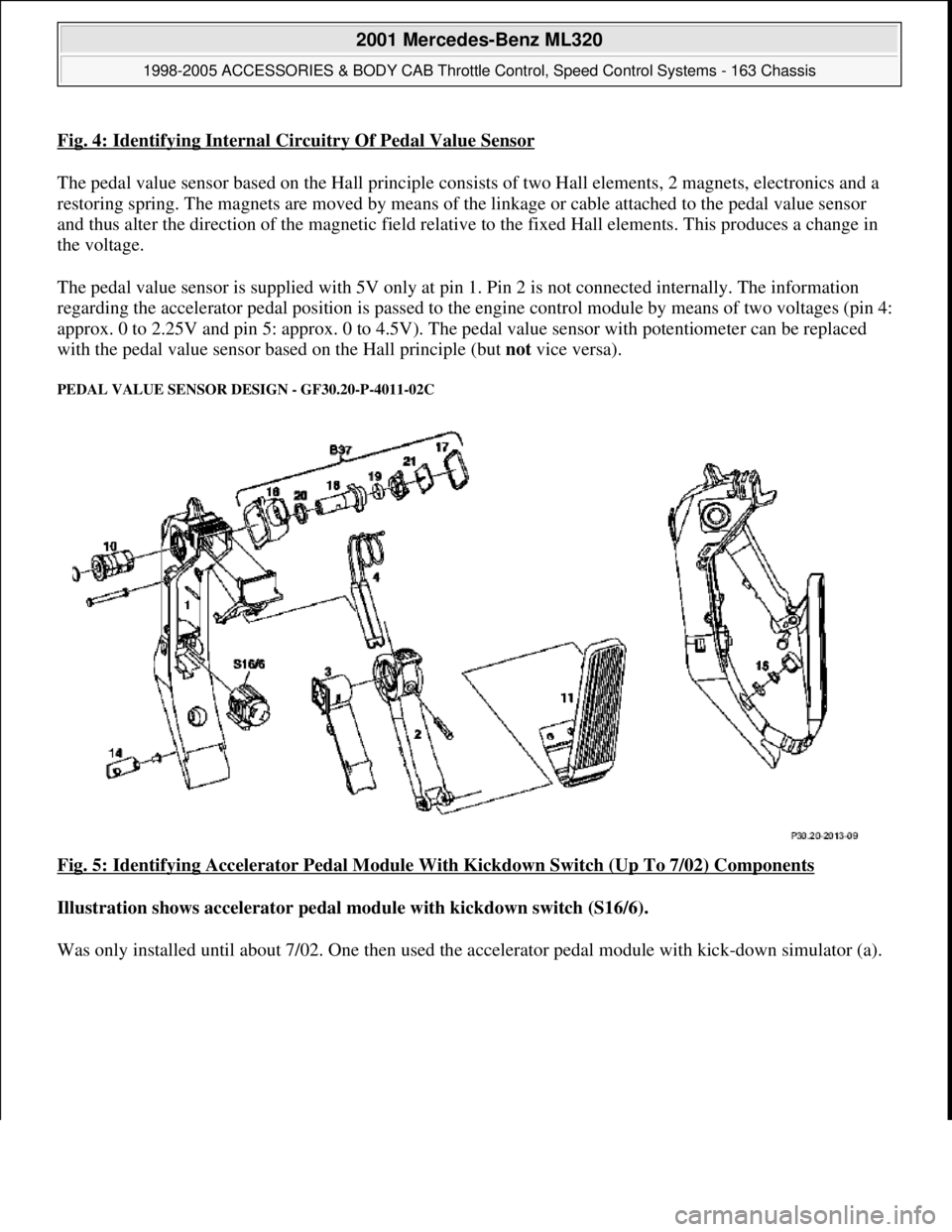
Fig. 4: Identifying Internal Circuitry Of Pedal Value Sensor
The pedal value sensor based on the Hall principle consists of two Hall elements, 2 magnets, electronics and a
restoring spring. The magnets are moved by means of the linkage or cable attached to the pedal value sensor
and thus alter the direction of the magnetic field relative to the fixed Hall elements. This produces a change in
the voltage.
The pedal value sensor is supplied with 5V only at pin 1. Pin 2 is not connected internally. The information
regarding the accelerator pedal position is passed to the engine control module by means of two voltages (pin 4:
approx. 0 to 2.25V and pin 5: approx. 0 to 4.5V). The pedal value sensor with potentiometer can be replaced
with the pedal value sensor based on the Hall principle (but not vice versa).
PEDAL VALUE SENSOR DESIGN - GF30.20-P-4011-02C
Fig. 5: Identifying Accelerator Pedal Module With Kickdown Switch (Up To 7/02) Components
Illustration shows accelerator pedal module with kickdown switch (S16/6).
Was onl
y installed until about 7/02. One then used the accelerator pedal module with kick-down simulator (a).
2001 Mercedes-Benz ML320
1998-2005 ACCESSORIES & BODY CAB Throttle Control, Speed Control Systems - 163 Chassis
me
Saturday, October 02, 2010 3:36:27 PMPage 6 © 2006 Mitchell Repair Information Company, LLC.
Page 3847 of 4133
Fig. 6: Identifying Accelerator Pedal Module With Kickdown Simulator (From 7/02) Components
Illustration shows accelerator pedal module with kickdown simulator (a).
Replace accelerator pedal module always complete!
Illustration shows internal circuitry of pedal value sensor B37 (Hall principle)
2001 Mercedes-Benz ML320
1998-2005 ACCESSORIES & BODY CAB Throttle Control, Speed Control Systems - 163 Chassis
me
Saturday, October 02, 2010 3:36:27 PMPage 7 © 2006 Mitchell Repair Information Company, LLC.
Page 3848 of 4133
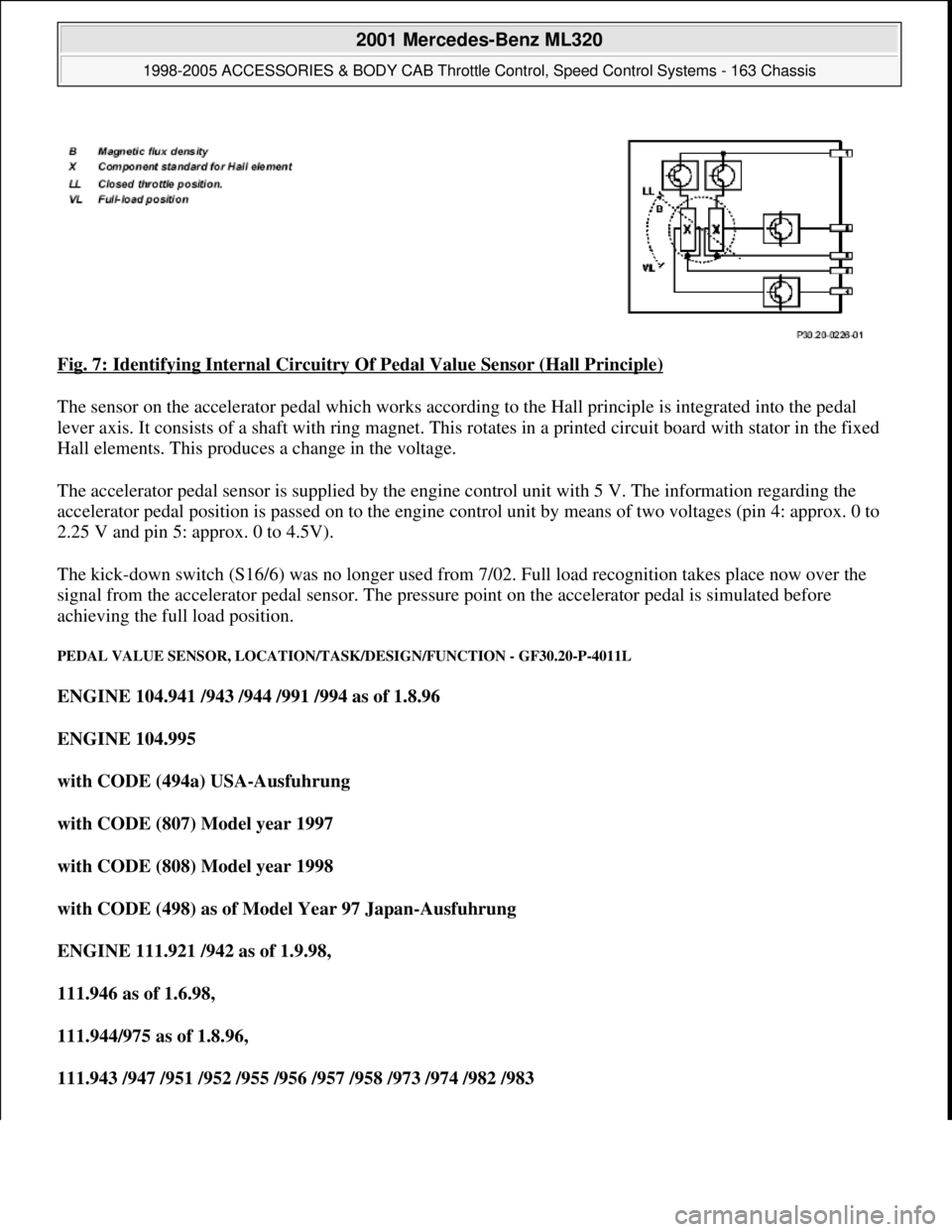
Fig. 7: Identifying Internal Circuitry Of Pedal Value Sensor (Hall Principle)
The sensor on the accelerator pedal which works according to the Hall principle is integrated into the pedal
lever axis. It consists of a shaft with ring magnet. This rotates in a printed circuit board with stator in the fixed
Hall elements. This produces a change in the voltage.
The accelerator pedal sensor is supplied by the engine control unit with 5 V. The information regarding the
accelerator pedal position is passed on to the engine control unit by means of two voltages (pin 4: approx. 0 to
2.25 V and pin 5: approx. 0 to 4.5V).
The kick-down switch (S16/6) was no longer used from 7/02. Full load recognition takes place now over the
signal from the accelerator pedal sensor. The pressure point on the accelerator pedal is simulated before
achieving the full load position.
PEDAL VALUE SENSOR, LOCATION/TASK/DESIGN/FUNCTION - GF30.20-P-4011L
ENGINE 104.941 /943 /944 /991 /994 as of 1.8.96
ENGINE 104.995
with CODE (494a) USA-Ausfuhrung
with CODE (807) Model year 1997
with CODE (808) Model year 1998
with CODE (498) as of Model Year 97 Japan-Ausfuhrung
ENGINE 111.921 /942 as of 1.9.98,
111.946 as of 1.6.98,
111.944/975 as of 1.8.96,
111.943 /947 /951 /952 /955 /956 /957 /958 /973 /974 /982 /983
2001 Mercedes-Benz ML320
1998-2005 ACCESSORIES & BODY CAB Throttle Control, Speed Control Systems - 163 Chassis
me
Saturday, October 02, 2010 3:36:27 PMPage 8 © 2006 Mitchell Repair Information Company, LLC.
Page 3850 of 4133
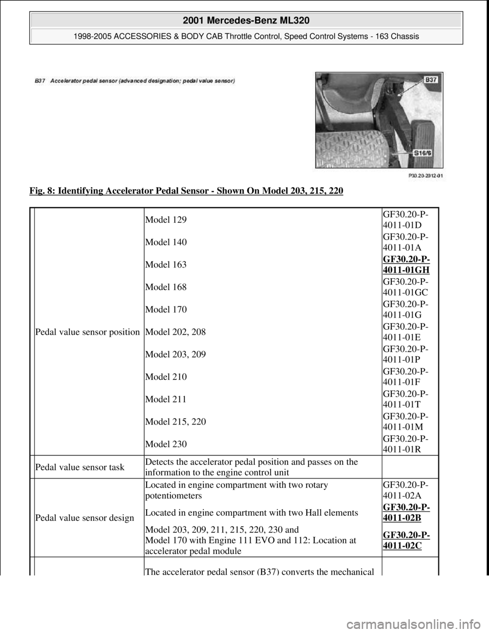
Fig. 8: Identifying Accelerator Pedal Sensor - Shown On Model 203, 215, 220
Pedal value sensor position
Model 129GF30.20-P-
4011-01D
Model 140GF30.20-P-
4011-01A
Model 163GF30.20-P-
4011-01GH
Model 168GF30.20-P-
4011-01GC
Model 170GF30.20-P-
4011-01G
Model 202, 208GF30.20-P-
4011-01E
Model 203, 209GF30.20-P-
4011-01P
Model 210GF30.20-P-
4011-01F
Model 211GF30.20-P-
4011-01T
Model 215, 220GF30.20-P-
4011-01M
Model 230GF30.20-P-
4011-01R
Pedal value sensor taskDetects the accelerator pedal position and passes on the
information to the engine control unit
Pedal value sensor design
Located in engine compartment with two rotary
potentiometersGF30.20-P-
4011-02A
Located in engine compartment with two Hall elementsGF30.20-P-
4011-02B
Model 203, 209, 211, 215, 220, 230 and
Model 170 with Engine 111 EVO and 112: Location at
accelerator pedal moduleGF30.20-P-
4011-02C
The accelerator pedal sensor (B37) converts the mechanical
2001 Mercedes-Benz ML320
1998-2005 ACCESSORIES & BODY CAB Throttle Control, Speed Control Systems - 163 Chassis
me
Saturday, October 02, 2010 3:36:27 PMPage 10 © 2006 Mitchell Repair Information Company, LLC.
Page 3851 of 4133
PEDAL VALUE SENSOR CHARACTERISTIC CURVE WHEN REVERSING FUNCTION - GF30.20-P-4013E
ENGINE 104.943 /944 /991 /994 as of 1.8.96
ENGINE 104.995
with CODE (494a) USA version
with CODE (807) Model year 1997
with CODE (808) Model year 1998
with CODE (498) as of Model year 97 Japanese version
ENGINE 104.941 as of 1.8.96
ENGINE 111.921 /942 as of 1.9.98,
111.946 as of 1.6.98,
111.944/975 as of 1.8.96,
111.943 /947 /951 /952 /955 /956 /957 /958 /973 /974 /982 /983
ENGINE 111.945
in MODEL 202.020 /080 as of 1.9.98,
208.335/435 as of 1.6.98
with CODE (494a) USA version
with CODE (807) Model year 1997
with CODE (808) Model year 1998
ENGINE
112.910 /911 /912 /913 /914 /916 /917 /920 /921 /922 /923 /940 /941 /942 /943 /944 /946 /947 /949 /953 /954 /9
5
ENGINE 113.940 /941 /942 /943 /948 /960 /961 /963 /965 /966 /967 /968 /969
Pedal value sensor functionactuation determined by the accelerator pedal into an
electrical signal according to the accelerator pedal position.
Pedal value sensor
characteristic curve when
reversing function
GF30.20-P-
4013E
2001 Mercedes-Benz ML320
1998-2005 ACCESSORIES & BODY CAB Throttle Control, Speed Control Systems - 163 Chassis
me
Saturday, October 02, 2010 3:36:27 PMPage 11 © 2006 Mitchell Repair Information Company, LLC.
Page 3852 of 4133
ENGINE 119.980 /981 /982 /985
ENGINE 120.982/983
ENGINE 137.970
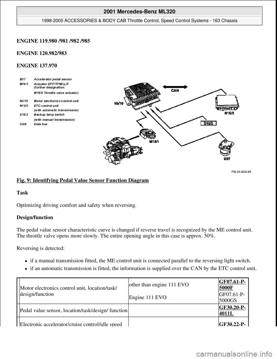
Fig. 9: Identifying Pedal Value Sensor Function Diagram
Task
Optimizing driving comfort and safety when reversing.
Design/function
The pedal value sensor characteristic curve is changed if reverse travel is recognized by the ME control unit.
The throttle valve opens more slowly. The entire opening angle in this case is approx. 50%.
Reversing is detected:
if a manual transmission fitted, the ME control unit is connected parallel to the reversing light switch.
if an automatic transmission is fitted, the information is supplied over the CAN by the ETC control unit.
Motor electronics control unit, location/task/
design/functionother than engine 111 EVOGF07.61-P-
5000F
Engine 111 EVOGF07.61-P-
5000GS
Pedal value sensor, location/task/design/ function GF30.20-P-
4011L
Electronic accelerator/cruise control/idle speed GF30.22-P-
2001 Mercedes-Benz ML320
1998-2005 ACCESSORIES & BODY CAB Throttle Control, Speed Control Systems - 163 Chassis
me
Saturday, October 02, 2010 3:36:27 PMPage 12 © 2006 Mitchell Repair Information Company, LLC.
Page 3854 of 4133
ENGINE 113.940 /941 /942 /943 /948 /960 /961 /963 /965 /966 /967 /968 /969
ENGINE 119.980 /981 /982 /985
ENGINE 137.970
Task
To allow safe further driving depending on the fault which has arisen in the electronic accelerator pedal system.
Pedal value sensor emergency mode
If the sensor in the pedal value sensor (B37) fails, the system will switch over to the second sensor. The throttle
valve opening is limited to approx. 60%. There is also dynamic limitation of the throttle valve's opening speed
where the throttle valve opening is delayed (the indicator lamp EPC does not light up).
If the plausibility check delivers a negative result or both sensors are defect only the idling speed will be
regulated (the indicator lamp EPC lights up).
Actuator for the throttle valve - emergency running, electrical
If a potentiometer in the actuator for the throttle valve breaks down the system switches-over to the second
intact potentiometer. The air flow mass serves as a second parameter for comparative purposes. Following a
plausibility check, the throttle valve opening is limited to approx. 60% in line with engine speed and load (EPC
indicator lamp does not come on).
If the plausibility check is negative or if both potentiometers are faulty, the throttle valve adopts a mechanical
emergency running position which is fixed by the spring capsule in the actuator (EPC indicator lamp comes on).
Actuator for the throttle valve - emergency running, mechanical emergency running stop
If the actuator motor is defect or there are other faults present the power supply to the actuator will be shut off.
The throttle valve then lies on the mechanical stop (spring box) so the throttle valve opening remains at a
constant 10-12°. At no engine load (idling) engine speed is regulated to about 900 rpm by shutting off or
activating the cylinders at the fuel side.
When driving, engine speed is controlled, in line with the engine load, by switching the cylinders off and on at
the fuel side. The maximum engine speed is about 1800 rpm. which is limited by the mechanical stop (the
indicator lamp EPC lights up).
Safety fuel shutoff
If a mechanical fault exists in the actuator, the safety fuel shutoff is activated.
Here the fuel injection valves are shut off for engine speeds < 1400 rpm and actuated again at speeds < 1200
rpm (the indicator lamp EPC li
ghts up).
2001 Mercedes-Benz ML320
1998-2005 ACCESSORIES & BODY CAB Throttle Control, Speed Control Systems - 163 Chassis
me
Saturday, October 02, 2010 3:36:27 PMPage 14 © 2006 Mitchell Repair Information Company, LLC.