Page 3455 of 4133
Fig. 170: Identifying Auxiliary Fan Components
REMOVE AND INSTALL RECEIVER/DRIER - AR83.30-P-6520GH
MODELS 163.113/136/ /154 /157 /172 /174 /175 with CODE (580) Air conditioning or Tempmatic for
USA
Remove/install
1Remove upper frame cross member
(1) AR62.30-P-
2300GH
2Unscrew bolts (2) for auxiliary fan
(M4) at radiator
3Disconnect additional fan connector
(M4x1)
4
Unclip electric cable for outside
temperature sensor at auxiliary fan
(M4)
5Pull out auxiliary fan (M4) upward
Installation: Insert additional fan in
the lower guides first pay attention to
correct seating.
6Install in the reverse order
2001 Mercedes-Benz ML320
1998-2005 HVAC Climate Control - 163 Chassis
me
Saturday, October 02, 2010 3:23:18 PMPage 211 © 2006 Mitchell Repair Information Company, LLC.
Page 3457 of 4133

Air conditioning system
Refrigerant compressor
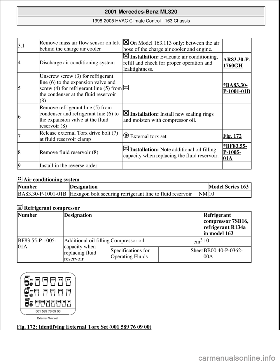
Fig. 172: Identifying External Torx Set (001 589 76 09 00)
3.1Remove mass air flow sensor on left
behind the charge air cooler On Model 163.113 only: between the air
hose of the charge air cooler and engine.
4Discharge air conditioning system
Installation: Evacuate air conditioning,
refill and check for proper operation and
leaktightness.AR83.30-P-
1760GH
5
Unscrew screw (3) for refrigerant
line (6) to the expansion valve and
screw (4) for refrigerant line (5) from
the condenser at the fluid reservoir
(8)
*BA83.30-
P-1001-01B
6
Remove refrigerant line (5) from
condenser and refrigerant line (6) to
the expansion valve at the fluid
reservoir (8)
Installation: Install new sealing rings
and moisten with compressor oil.
7Release external Torx drive bolt (7)
at fluid reservoir clamp External torx setFig. 172
8Remove fluid reservoir (8) Installation: Note additional oil filling
capacity when replacing the fluid reservoir.*BF83.55-
P-1005-
01A
9Install in the reverse order
NumberDesignationModel Series 163
BA83.30-P-1001-01BHexagon bolt securing refrigerant line to fluid reservoirNM10
NumberDesignationRefrigerant
compressor 7SB16,
refrigerant R134a
in model 163
BF83.55-P-1005-
01AAdditional oil filling
capacity when
replacing fluid
reservoirCompressor oilcm3 10
Specifications for
Operating FluidsSheetBB00.40-P-0362-
00A
2001 Mercedes-Benz ML320
1998-2005 HVAC Climate Control - 163 Chassis
me
Saturday, October 02, 2010 3:23:18 PMPage 213 © 2006 Mitchell Repair Information Company, LLC.
Page 3461 of 4133
Fig. 174: Identifying Air Conditioning Control Module Components
REMOVE AND INSTALL EVAPORATOR TEMPERATURE SENSOR - AR83.30-P-8085GH
MODEL 163 with CODE (580) Air conditioning or Tempmatic for USA
Fig. 175: Identifying Evaporator Temperature Sensor Components
Removal, installation
1Disconnect ground cable of battery AR54.10-P-0003A
2Remove switch unit for heater/ ventilation (1) AR83.20-P-
1835GH
3Unscrew bolt (4) for air conditioning control module (N19) at
evaporator housing (3)
4Disconnect connector (5) at air conditioning control module (N19)
5Detach air conditioning control module (N19) from evaporator
housing (3)
6Install in the reverse order
7Encode radio AR82.60-P-7502-
01GH
8Read out diagnostic trouble code memory, erase and set clock
2001 Mercedes-Benz ML320
1998-2005 HVAC Climate Control - 163 Chassis
me
Saturday, October 02, 2010 3:23:19 PMPage 217 © 2006 Mitchell Repair Information Company, LLC.
Page 3462 of 4133

REMOVE/INSTALL OUTSIDE AIR TEMPERATURE SENSOR - AR83.30-P-8086GH
MODELS 163.113 #A up to 289564, 163.154 #A as of 145272 up to 289564, 163.172 #A as of 145272,
163.174 #A up to 289564, 163.113 #X up to 754619, 163.136 #X as of 708319, 163.154 #X as of 708319 up
to 754619, 163.172 #X as of 708319 with CODE (580) Air conditioning or Tempmatic for USA
Remove/Install
Risk of explosion from welding or
soldering work on closed air
conditioning system. Risk of
poisoning. Inhaling overheated
refrigerant vapors may be toxic. Risk
of injury. Contact with liquid
refrigerant may result in injury to the
skin and eyes.Do not carry out any welding work on the
closed air conditioning system or in the
surrounding area. No smoking or open
flames. Wear eye protection and protective
gloves. Work only in well ventilated areas.
Carry out repair work on the air
conditioning system circuit only after the
system has been discharged.
AS83.00-
Z-0001-
01A
Procedures if air conditioning system is
damaged or leakingAll models
AH83.30-
N-0004-
01A
Protect air conditioning circuit and
components from moisture when
carrying out repair work
All models fitted with air conditioning
AH83.30-
N-0005-
01A
Notes on handling refrigerant R134aAll models fitted with air conditioning
AH83.30-
N-0003-
01A
1Remove evaporator housing AR83.30-
P-5200GH
2Disassemble AC housing AR83.30-
P-5201GH
3Unclip evaporator temperature sensor
(B10/6) from evaporator (1)
4Install in the reverse order
2001 Mercedes-Benz ML320
1998-2005 HVAC Climate Control - 163 Chassis
me
Saturday, October 02, 2010 3:23:19 PMPage 218 © 2006 Mitchell Repair Information Company, LLC.
Page 3463 of 4133
Fig. 176: Identifying Coolan t Compensating Reservoir
Fig. 177: Identifying Outside Air Te mperature Sensor And Connector
2001 Mercedes-Benz ML320
1998-2005 HVAC Climate Control - 163 Chassis
me
Saturday, October 02, 2010 3:23:19 PMPage 219 © 2006 Mitchell Repair Information Company, LLC.
Page 3465 of 4133

Dashboard
Air conditioning system
8Remove wiper system AR82.30-P-
6400GH
9Remove nuts (5) from instrument
panel at firewall
*BA68.10-
P-1001-
01A
10Remove paneling from A-pillar AR68.30-P-
4050GH
11Remove plastic nuts on driver's side
at paneling below instrument panel
12Remove paneling on right in footwell AR68.30-P-
4010GH
13
Remove rubber covers on side at the
A-pillars and unscrew screws for
instrument panel at A-pillar (arrows)
*BA68.10-
P-1002-
01A
14Remove center console AR68.20-P-
2000GH
15Unscrew bolt (6) underneath the
instrument panel
*BA68.10-
P-1003-
01A
16Withdraw instrument panel to the
rear Bring in helper. Cushion front edge of
selector lever module so that lower edge of
instrument panel is not damaged.
17Turn instrument panel around so that
the back is accessible Do not overstretch interior wiring
harness.
18Detach outside temperature sensor
connector (B10/5x1)
19Disconnect cable from temperature
sensor to evaporator housing Installation: Ensure clean cable routing.
20Remove outside temperature sensor
(B10/5) from air duct 2 bolts.
21Install in the reverse order
22Inspect cooling system for leaks AR20.00-P-
1010HA
NumberDesignationModel Series 163
BA68.10-P-1001-01ANut, dashboard to firewallNM8
BA68.10-P-1002-01ABolt, dashboard to A-pillarNM19
BA68.10-P-1003-01ABolt, dashboard to transmission tunnelNM30
NumberDesignationModel Series 163
BA83.30-P-1003-01BNut to pipeline on expansion valveNM10
2001 Mercedes-Benz ML320
1998-2005 HVAC Climate Control - 163 Chassis
me
Saturday, October 02, 2010 3:23:19 PMPage 221 © 2006 Mitchell Repair Information Company, LLC.
Page 3466 of 4133

REMOVE/INSTALL AIR OUTLET TEMPERATURE SENSOR - AR83.30-P-8087GH
MODEL 163.113 #A as of 289565, 163.154 #A as of 289620, 163.174 #A as of 289565, 163.113 #X as of
754620, 163.128/157/175
Instrument panel center nozzles
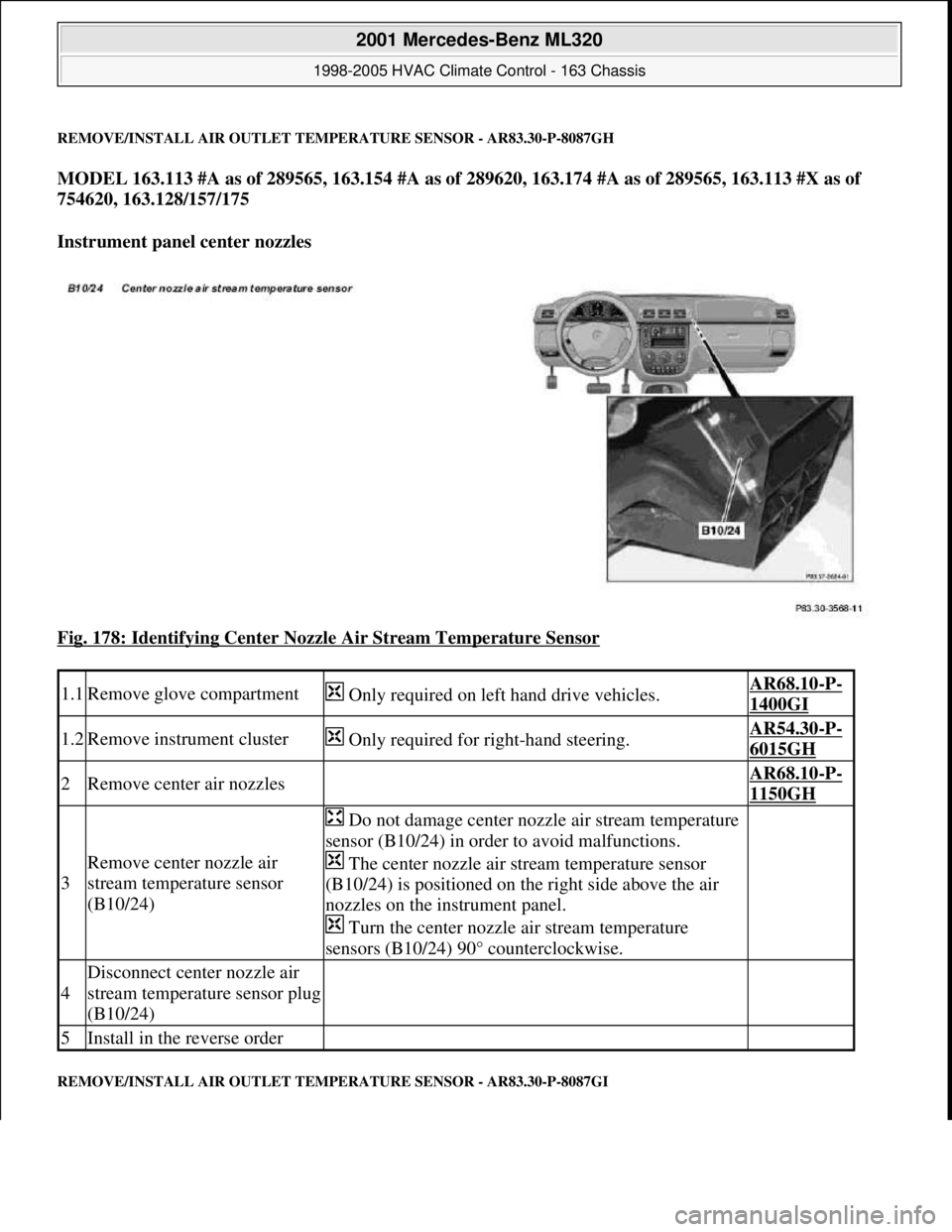
Fig. 178: Identifying Center Nozzle Air Stream Temperature Sensor
REMOVE/INSTALL AIR OUTLET TEMPERATURE SENSOR - AR83.30-P-8087GI
1.1Remove glove compartment Only required on left hand drive vehicles.AR68.10-P-
1400GI
1.2Remove instrument cluster Only required for right-hand steering.AR54.30-P-
6015GH
2Remove center air nozzles AR68.10-P-
1150GH
3
Remove center nozzle air
stream temperature sensor
(B10/24)
Do not damage center nozzle air stream temperature
sensor (B10/24) in order to avoid malfunctions.
The center nozzle air stream temperature sensor
(B10/24) is positioned on the right side above the air
nozzles on the instrument panel.
Turn the center nozzle air stream temperature
sensors (B10/24) 90° counterclockwise.
4
Disconnect center nozzle air
stream temperature sensor plug
(B10/24)
5Install in the reverse order
2001 Mercedes-Benz ML320
1998-2005 HVAC Climate Control - 163 Chassis
me
Saturday, October 02, 2010 3:23:19 PMPage 222 © 2006 Mitchell Repair Information Company, LLC.
Page 3467 of 4133
MODEL 163.113 /154 /174 #A as of 289565, 163.113 #X as of 754620, 163.128/157/175
Driver's side footwell
Fig. 179: Identifying Front Footwell Air Stream Temperature Sensor
REMOVE/INSTALL AIR OUTLET TEMPERATURE SENSOR - AR83.30-P-8087GJ
MODEL 163.113 /154 /174 #A as of 289565, 163.113 #X as of 754620, 163.128/157/175
Blower motor in rear
Remove/install
1Remove cover below instrument
panel AR68.10-P-
1500GH
2
Disconnect plug from front footwell
air stream temperature sensor
(B10/25)
3Remove front footwell air stream
temperature sensor(B10/25)
Do not damage front footwell air
stream temperature sensor (B10/25).
Turn front footwell air stream
temperature sensor (B10/25) 90
counterclockwise.
4Install in the reverse order
2001 Mercedes-Benz ML320
1998-2005 HVAC Climate Control - 163 Chassis
me
Saturday, October 02, 2010 3:23:19 PMPage 223 © 2006 Mitchell Repair Information Company, LLC.