Page 2459 of 4133
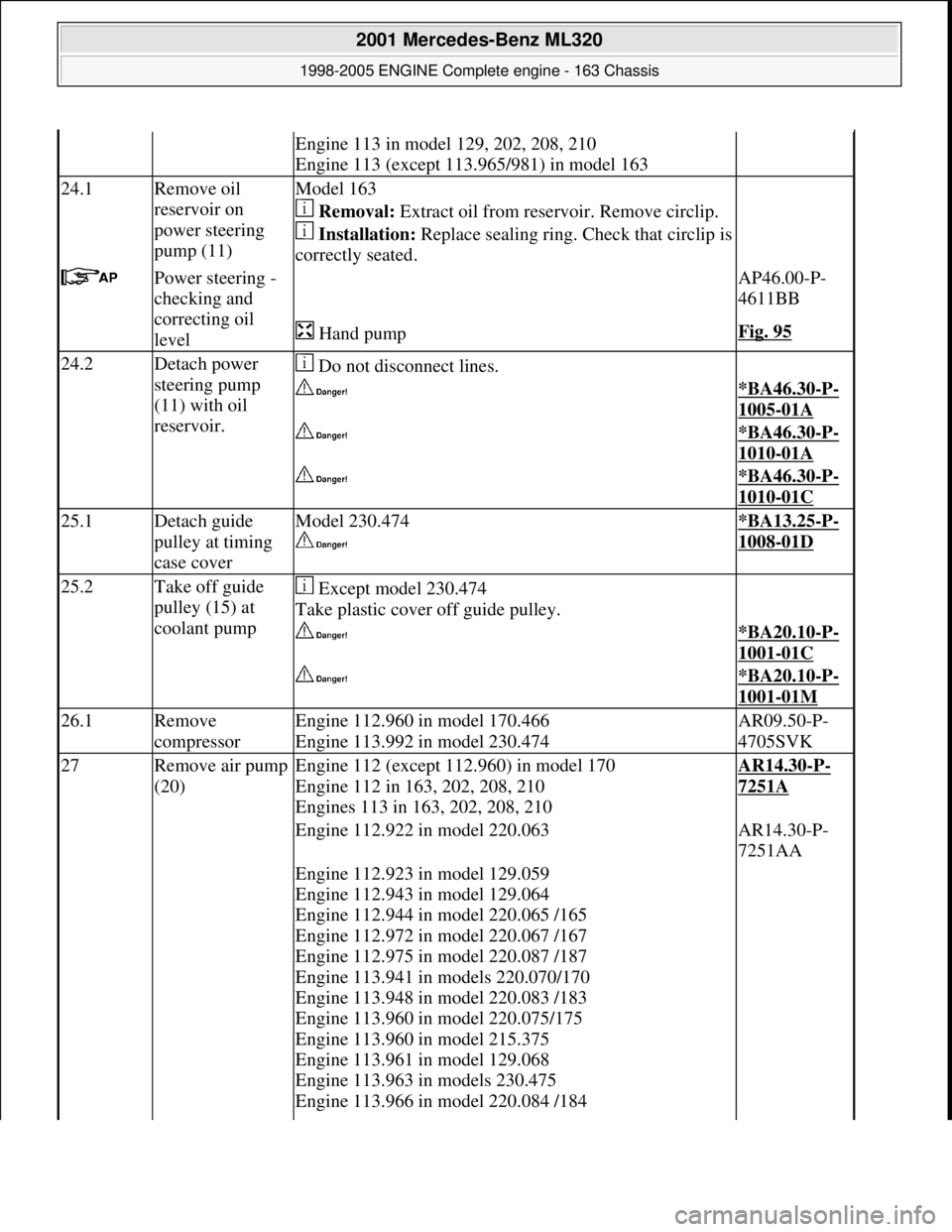
Engine 113 in model 129, 202, 208, 210
Engine 113 (except 113.965/981) in model 163
24.1Remove oil
reservoir on
power steering
pump (11)Model 163
Removal: Extract oil from rese rvoir. Remove circlip.
Installation: Replace sealing ring. Ch eck that circlip is
correctly seated.
Power steering -
checking and
correcting oil
level AP46.00-P-
4611BB
Hand pumpFig. 95
24.2Detach power
steering pump
(11) with oil
reservoir. Do not disconnect lines.
*BA46.30-P-
1005-01A
*BA46.30-P-
1010-01A
*BA46.30-P-
1010-01C
25.1Detach guide
pulley at timing
case coverModel 230.474
*BA13.25-P-
1008-01D
25.2Take off guide
pulley (15) at
coolant pump Except model 230.474
Take plastic cover off guide pulley.
*BA20.10-P-
1001-01C
*BA20.10-P-
1001-01M
26.1Remove
compressorEngine 112.960 in model 170.466
Engine 113.992 in model 230.474AR09.50-P-
4705SVK
27Remove air pump
(20)Engine 112 (except 112.960) in model 170
Engine 112 in 163, 202, 208, 210
Engines 113 in 163, 202, 208, 210AR14.30-P-
7251A
Engine 112.922 in model 220.063AR14.30-P-
7251AA
Engine 112.923 in model 129.059
Engine 112.943 in model 129.064
Engine 112.944 in model 220.065 /165
Engine 112.972 in model 220.067 /167
Engine 112.975 in model 220.087 /187
Engine 113.941 in models 220.070/170
Engine 113.948 in model 220.083 /183
Engine 113.960 in model 220.075/175
Engine 113.960 in model 215.375
Engine 113.961 in model 129.068
Engine 113.963 in models 230.475
Engine 113.966 in model 220.084 /184
2001 Mercedes-Benz ML320
1998-2005 ENGINE Complete engine - 163 Chassis
me
Saturday, October 02, 2010 3:17:57 PMPage 103 © 2006 Mitchell Repair Information Company, LLC.
Page 2476 of 4133
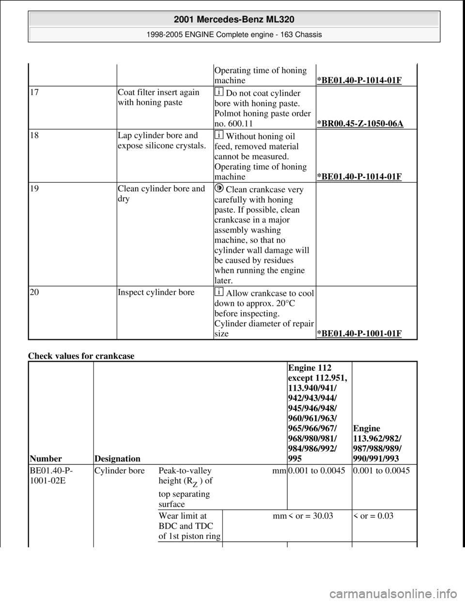
Check values for crankcase
Operating time of honing
machine
*BE01.40-P-1014-01F
17Coat filter insert again
with honing paste Do not coat cylinder
bore with honing paste.
Polmot honing paste order
no. 600.11
*BR00.45-Z-1050-06A
18Lap cylinder bore and
expose silicone crystals. Without honing oil
feed, removed material
cannot be measured.
Operating time of honing
machine
*BE01.40-P-1014-01F
19Clean cylinder bore and
dry Clean crankcase very
carefully with honing
paste. If possible, clean
crankcase in a major
assembly washing
machine, so that no
cylinder wall damage will
be caused by residues
when running the engine
later.
20Inspect cylinder boreAllow crankcase to cool
down to approx. 20°C
before inspecting.
Cylinder diameter of repair
size
*BE01.40-P-1001-01F
NumberDesignation
Engine 112
except 112.951,
113.940/941/
942/943/944/
945/946/948/
960/961/963/
965/966/967/
968/980/981/
984/986/992/
995
Engine
113.962/982/
987/988/989/
990/991/993
BE01.40-P-
1001-02E Cylinder borePeak-to-valley
height (R
Z ) of
top separating
surface
mm0.001 to 0.00450.001 to 0.0045
Wear limit at
BDC and TDC
of 1st piston ringmm< or = 30.03< or = 0.03
2001 Mercedes-Benz ML320
1998-2005 ENGINE Complete engine - 163 Chassis
me
Saturday, October 02, 2010 3:17:57 PMPage 120 © 2006 Mitchell Repair Information Company, LLC.
Page 2484 of 4133
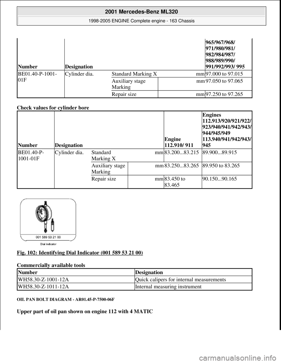
Check values for cylinder bore
Fig. 102: Identifying Dial Indicator (001 589 53 21 00)
Commercially available tools
OIL PAN BOLT DIAGRAM - AR01.45-P-7500-06F
Upper part of oil pan shown on engine 112 with 4 MATIC
NumberDesignation
965/967/968/
971/980/981/
982/984/987/
988/989/990/
991/992/993/ 995
BE01.40-P-1001-
01FCylinder dia.Standard Marking Xmm97.000 to 97.015
Auxiliary stage
Marking mm97.050 to 97.065
Repair sizemm97.250 to 97.265
NumberDesignation
Engine
112.910/ 911
Engines
112.913/920/921/922/
923/940/941/942/943/
944/945/949
113.940/941/942/943/
945
BE01.40-P-
1001-01FCylinder dia.Standard
Marking Xmm83.200...83.21589.900...89.915
Auxiliary stage
Marking mm83.250...83.26589.950 to 83.265
Repair sizemm83.450 to
83.46590.150...90.165
NumberDesignation
WH58.30-Z-1001-12AQuick calipers for internal measurements
WH58.30-Z-1011-12AInternal measuring instrument
2001 Mercedes-Benz ML320
1998-2005 ENGINE Complete engine - 163 Chassis
me
Saturday, October 02, 2010 3:17:57 PMPage 128 © 2006 Mitchell Repair Information Company, LLC.
Page 2509 of 4133
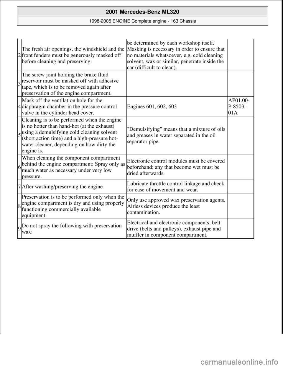
2
The fresh air openings, the windshield and the
front fenders must be generously masked off
before cleaning and preserving.
be determined by each workshop itself.
Masking is necessary in order to ensure that
no materials whatsoever, e.g. cold cleaning
solvent, wax or similar, penetrate inside the
car (difficult to clean).
3
The screw joint holding the brake fluid
reservoir must be masked off with adhesive
tape, which is to be removed again after
preservation of the engine compartment.
4
Mask off the ventilation hole for the
diaphragm chamber in the pressure control
valve in the cylinder head cover.
Engines 601, 602, 603
AP01.00-
P-8503-
01A
5
Cleaning is to be performed when the engine
is no hotter than hand-hot (at the exhaust)
using a demulsifying cold cleaning solvent
(short action time) and a high-pressure hot-
water cleaner, depending on how dirty the
engine is.
"Demulsifying" means that a mixture of oils
and greases in water separated in the oil
separator pipe.
6
When cleaning the component compartment
behind the engine compartment: Spray only as
much water as necessary under very low
pressure.Electronic control modul es must be covered
beforehand; any that become wet must be
dried afterwards.
7After washing/preserving the engineLubricate throttle cont rol linkage and check
for ease of movement and wear.
8
Preservation is to be performed only when the
engine compartment is dry and using properly
functioning commercially available
equipment.Only use approved wax preservation agents.
Airless devices produce the least
contamination.
9Do not spray the follow ing with preservation
wax:Electrical and electroni c components, belt
drive (belts and pulleys), exhaust pipe and
muffler in component compartment.
2001 Mercedes-Benz ML320
1998-2005 ENGINE Complete engine - 163 Chassis
me
Saturday, October 02, 2010 3:17:58 PMPage 153 © 2006 Mitchell Repair Information Company, LLC.
Page 2559 of 4133
Fig. 64: Identifying Torque Meter (001 589 49 21 00)
Commercially available tools
1. Measure and note friction torque using torque meter (040b) and connecting piece on the hexagon collared
nut.
Fig. 65: Identifying Torque Meter
CHECK FRONT AXLE GEAR OIL LEVEL AND TOP UP IF NECESSARY - AR33.30-P-0525-02GH
Modification notes
Front final-drive unit
Front axle gear
NumberDesignation
WH58.30-Z-1013-06AWrench bit 41 mm hexagon 3/4 inch four-point
8.1.07Filling capacity, Specifications for Operating FluidsModel 163*BF33.30-P-1001-03B
NumberDesignationModel 163
BA33.30-P-1002-03BOil filler screw, front axle gearNm50
BA33.30-P-1003-03BOil drain screw, front axle gearNm50
NumberDesignationModel 163
BF33.30-P-1001-
03BFilling capacityFront axle gearLiters1.2
Specifications for SheetBB00.40-P-0235-
2001 Mercedes-Benz ML320
1998-2005 DRIVELINE/AXLES Front Axle - 163 Chassis
me
Saturday, October 02, 2010 3:38:22 PMPage 40 © 2006 Mitchell Repair Information Company, LLC.
Page 2560 of 4133
1. Clean area around oil fi ller screw (14f).
2. Remove oil filler screw (14f).
The front axle gear is correctly filled when the oil reaches the lower edge of the filler opening. Top up
if necessary. If the oil level check is car ried out when the front axle gear is warm , do not drain off oil
discharged as a result of thermal expansion.
Fig. 66: Identifying Oil Filler Screw
3. Replace seal ring for oil filler screw.
4. Screw in oil filler screw and tighten.
Fig. 67: Identifying Oil Drain Screw
REMOVE/INSTALL FRONT AX LE GEAR - AR33.30-P-0525GH
MODEL 163.113 /128 /136 /154 /157 /172 /174 /175
Operating Fluids07B
2001 Mercedes-Benz ML320
1998-2005 DRIVELINE/AXLES Front Axle - 163 Chassis
me
Saturday, October 02, 2010 3:38:22 PMPage 41 © 2006 Mitchell Repair Information Company, LLC.
Page 2561 of 4133
Fig. 68: Identifying Front Axle Gear Components
Modification notes
8.1.07Filling capacity, Specifications for Operating FluidsModel 163*BF33.30-P-1001-03B
Remove/install
1
Remove front wheels
Remove/install wheels, rotate if
necessaryAP40.10-P-
4050GH
2Drain front axle gear oil
Installation: ?
Check front axle gear oil level and
top up if necessary
Oil drain screw: ?AR33.30-P-
0525-02GH
Oil filler plug: ?*BA33.30-P-
1003-03B
*BA33.30-P-
1002-03B
*BF33.30-P-
1001-03B
3Unbolt propeller shaft at flange on front
axle transmission *BA41.20-P-
1001-01A
4Press both follower joints out of upper
transverse control arms using puller
Check rubber boot and ball joint for
wear and damage.AR33.20-P-
0500-01GH
*BA33.20-P-
1001-01D
2001 Mercedes-Benz ML320
1998-2005 DRIVELINE/AXLES Front Axle - 163 Chassis
me
Saturday, October 02, 2010 3:38:22 PMPage 42 © 2006 Mitchell Repair Information Company, LLC.
Page 2565 of 4133
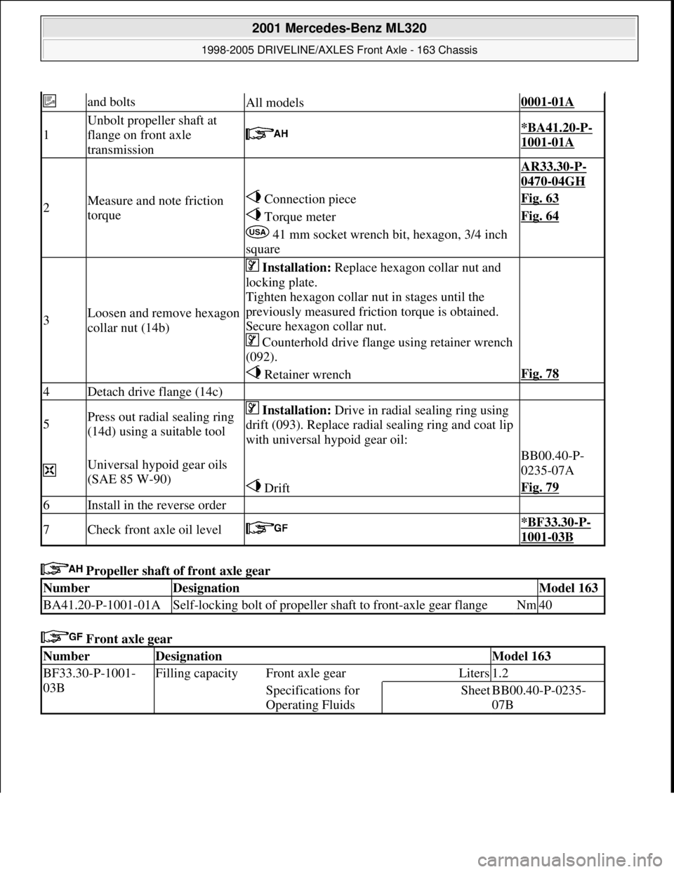
Propeller shaft of front axle gear
Front axle gear
and boltsAll models0001-01A
1
Unbolt propeller shaft at
flange on front axle
transmission
*BA41.20-P-
1001-01A
2Measure and note friction
torque
AR33.30-P-
0470-04GH
Connection pieceFig. 63
Torque meterFig. 64
41 mm socket wrench bit, hexagon, 3/4 inch
square
3Loosen and remove hexagon
collar nut (14b)
Installation: Replace hexagon collar nut and
locking plate.
Tighten hexagon collar nut in stages until the
previously measured friction torque is obtained.
Secure hexagon collar nut.
Counterhold drive flange using retainer wrench
(092).
Retainer wrenchFig. 78
4Detach drive flange (14c)
5Press out radial sealing ring
(14d) using a suitable tool Installation: Drive in radial sealing ring using
drift (093). Replace radial sealing ring and coat lip
with universal hypoid gear oil:
Universal hypoid gear oils
(SAE 85 W-90) BB00.40-P-
0235-07A
DriftFig. 79
6Install in the reverse order
7Check front axle oil level *BF33.30-P-
1001-03B
NumberDesignationModel 163
BA41.20-P-1001-01ASelf-locking bolt of propeller shaft to front-axle gear flangeNm40
NumberDesignationModel 163
BF33.30-P-1001-
03BFilling capacity Front axle gearLiters1.2
Specifications for
Operating FluidsSheetBB00.40-P-0235-
07B
2001 Mercedes-Benz ML320
1998-2005 DRIVELINE/AXLES Front Axle - 163 Chassis
me
Saturday, October 02, 2010 3:38:22 PMPage 46 © 2006 Mitchell Repair Information Company, LLC.