1997 MERCEDES-BENZ ML350 check oil
[x] Cancel search: check oilPage 3459 of 4133
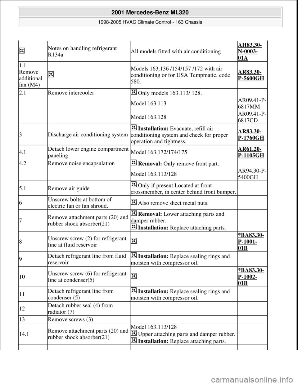
Notes on handling refrigerant
R134aAll models fitted with air conditioning
AH83.30-
N-0003-
01A
1.1
Remove
additional
fan (M4)
Models 163.136 /154/157 /172 with air
conditioning or for USA Tempmatic, code
580.AR83.30-
P-5600GH
2.1Remove intercooler Only models 163.113/ 128.
Model 163.113AR09.41-P-
6817MM
Model 163.128AR09.41-P-
6817CD
3Discharge air conditioning system
Installation: Evacuate, refill air
conditioning system and check for proper
operation and tightness.AR83.30-
P-1760GH
4.1Detach lower engine compartment
panelingModel 163.172/174/175AR61.20-
P-1105GH
4.2Remove noise encapsulation Removal: Only remove front part.
Model 163.113/128AR94.30-P-
5400GH
5.1Remove air guide Only if present Located at front
crossmember, in center behind front bumper.
6Unscrew bolts at bottom of
electric fan or fan shroud. Also remove sheet metal nuts.
7Remove attachment parts (20) and
rubber shock absorber(21) Removal: Lower attaching parts and
damper rubber.
Installation: Replace attaching parts.
8Unscrew screw (2) for refrigerant
line at fluid reservoir
*BA83.30-
P-1001-
01B
9Detach refrigerant line from fluid
reservoir Installation: Replace sealing rings and
moisten with compressor oil.
10Unscrew screw (6) for refrigerant
line at condenser(5)
*BA83.30-
P-1002-
01B
11Detach refrigerant line from
condenser (5) Installation: Replace sealing rings and
moisten with compressor oil.
12Detach rubber seal (4) from
radiator (7)
13Remove screws (3)
14.1Remove attachment parts (20) and
rubber shock absorber(21)Model 163.113/128
Upper attaching parts and damper rubber.
Installation: Replace attaching parts.
2001 Mercedes-Benz ML320
1998-2005 HVAC Climate Control - 163 Chassis
me
Saturday, October 02, 2010 3:23:18 PMPage 215 © 2006 Mitchell Repair Information Company, LLC.
Page 3464 of 4133
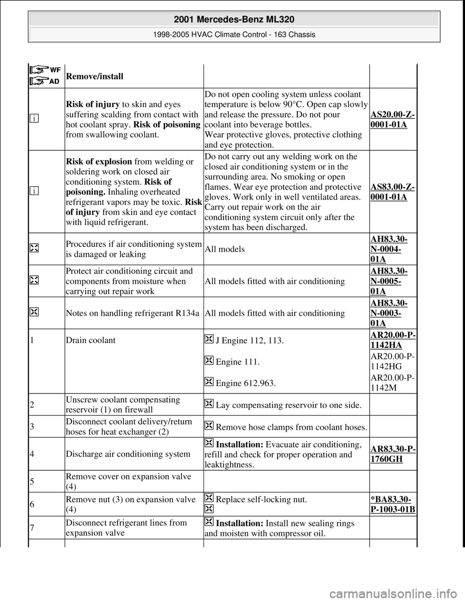
Remove/install
Risk of injury to skin and eyes
suffering scalding from contact with
hot coolant spray. Risk of poisoning
from swallowing coolant.
Do not open cooling system unless coolant
temperature is below 90°C. Open cap slowly
and release the pressure. Do not pour
coolant into beverage bottles.
Wear protective gloves, protective clothing
and eye protection.
AS20.00-Z-
0001-01A
Risk of explosion from welding or
soldering work on closed air
conditioning system. Risk of
poisoning. Inhaling overheated
refrigerant vapors may be toxic. Risk
of injury from skin and eye contact
with liquid refrigerant.Do not carry out any welding work on the
closed air conditioning system or in the
surrounding area. No smoking or open
flames. Wear eye protection and protective
gloves. Work only in well ventilated areas.
Carry out repair work on the air
conditioning system circuit only after the
system has been discharged.
AS83.00-Z-
0001-01A
Procedures if air conditioning system
is damaged or leakingAll models
AH83.30-
N-0004-
01A
Protect air conditioning circuit and
components from moisture when
carrying out repair work
All models fitted with air conditioning
AH83.30-
N-0005-
01A
Notes on handling refrigerant R134aAll models fitted with air conditioning
AH83.30-
N-0003-
01A
1Drain coolant J Engine 112, 113.AR20.00-P-
1142HA
Engine 111.AR20.00-P-
1142HG
Engine 612.963.AR20.00-P-
1142M
2Unscrew coolant compensating
reservoir (1) on firewall Lay compensating reservoir to one side.
3Disconnect coolant delivery/return
hoses for heat exchanger (2) Remove hose clamps from coolant hoses.
4Discharge air conditioning system
Installation: Evacuate air conditioning,
refill and check for proper operation and
leaktightness.AR83.30-P-
1760GH
5Remove cover on expansion valve
(4)
6Remove nut (3) on expansion valve
(4) Replace self-locking nut.
*BA83.30-
P-1003-01B
7Disconnect refrigerant lines from
expansion valve Installation: Install new sealing rings
and moisten with compressor oil.
2001 Mercedes-Benz ML320
1998-2005 HVAC Climate Control - 163 Chassis
me
Saturday, October 02, 2010 3:23:19 PMPage 220 © 2006 Mitchell Repair Information Company, LLC.
Page 3482 of 4133

GF54.30-P-3003A
Indicator/warning messages triggered via CAN data buses, function
24.10.96
MODEL
129, 140 as of 1.6.96,
163, 168, 170,
202 as of 1.8.96,
208 up to 31.7.99,
210 as of 1.6.96 up to 30.6.99
Indicator and warning displays triggered via CAN
Low brake fluid level/parking brake indicator lamp (A1e7)
The parking brake signal comes from the traction system
control module.
The brake fluid signal comes directly from the switch (S11)
(except model 163).
Brake pad wear indicator lamp (A1e6)
The parking brake signal comes from the traction system
control module (N47)
Low engine oil level indicator lamp (A1e12)
The oil level signal comes from the injection system control
module (N3).
For vehicles with ASSYST, also refer to document: ASSYST
engine oil monitoring.
Preglow indicator lamp (A1e16)
The signal comes directly from the injection system control
module (N3).
Coolant level and temperature warning lamp (A1e11) model 168
only as of 9.99
The coolant temperature signal comes from the injection
system control module (N3)
-----------------------------------------------------------------------------------------
ABS MIL (A1e17)
The parking brake signal comes from the traction system
control module (N47).
"CHECK ENGINE" MIL (A1e26),
I
only
The signal comes from the injection system control module (N3)
ETS (A1e35) or ASR (A1e22) or ESP (A1e42) MIL
Lamp illuminated if there is a fault in the respective system.
The signal comes from the traction system control module
(N47).
ETS (A1e36) or ASR (A1e21) or ESP (A1e41) warning lamp
The lamp indicates that the respective system is active.
The signal comes from the traction system control module
(N47).
-----------------------------------------------------------------------------------------
Severe leak warning (
I
as of 97 only)
The fuel reserve indicator lamp (A1e4) flashes. The signal
comes from the injection system control module (N3).
The warning takes place at the earliest 30 minutes after cold
start with the engine idling and the vehicle stationary.
Also refer to document: Purge system with leak test, function
Fog lamps indicator lamp (A1e57), model 163 only except
I
)
The signal comes from the All-activity module (AAM, N10)
"LOW RANGE" indicator lamp (A1e53), model 163 only
The signal comes from the transfer case control module (N78)
Active service system (ASSYST)
Engines 112, 113, 611 (engines with oil
sensor)
GF00.20-P-2009A
Engine oil monitoring, function
Model 210 as of 01.03.97 with engine M111,
OM602, OM604, OM605 and OM606
As of 06.97 models 129, 140, 170, 202 except
engines 112, 113, 611
(Valid for engines with low oil level switch).
GF00.20-P-2009B
Displaying coolant temperature, function
Model 168 as of 9.99
GF54.30-P-3020GC
Purge system with leak test, function
GF47.30-P-3016L
Bus systems, overall function
GF54.00-P-0004A
Copyright DaimlerChrysler AG 04.06.2006 CD-Ausgabe G/10/04 . This WIS print-out will not be recorde
d by Modification services.
Page 1
Page 3484 of 4133

AH40.10-P-9411-01A
Information on tires/rims
Model 124, 129, 140, 163, 168, 169,
170, 171, 199, 201, 202, 203, 208, 209,
210, 211, 215, 219, 220, 230, 240, 414,
450, 452,
639
Tires
D
For service conversions, the tire/disc wheel specifications and
dimensions should be compared with the entries in the
registration papers.
D
When mounting tires, the tires and rims must be carefully
matched in order to guarantee the concentricity of the wheel.
Identification of matching points on:
- Tires with a colored dot on the outside of the tire,
- Sheet steel disk wheel by a colored dot or punch mark on the
outside of the wheel,
- Perform this operation at the valve stem hole on light-alloy
disk wheels
With an additional paint spot or punch mark in the rim base
for the 140 Model Series.
D
Always replace the rubber valve.
-----------------------------------------------------------------------------------------
D
Damaged and defective tires must always be replaced. The
repair methods employed in the tire trade are not approved by
Mercedes-Benz. Small nicks (<0.8mm) on the tire's sidewall do
not usually pose a cause for concern, and continued use of
such tires is approved
D When replacing just one tire, install it on the front of the vehicle.
This does not apply to vehicles with different tires of varying
specifications on the front and rear wheels.
D
Only use tires listed in the valid Service Information bulletins
and repair instructions.
D
If the permissible maximum speed of an M+S tire is below the
maximum speed of the vehicle, an appropriate adhesive plate
must be attached in the driver's field of view.
-----------------------------------------------------------------------------------------
D
Tires permissible for higher speeds may be used.
D
Always fit all rims with tires of the same design, make and
version.
-----------------------------------------------------------------------------------------
D
Run in new tires for approx. 100 km at moderate speed.
D
Handed tires must be installed according to the arrow on the
side wall of the tire.
D
Tires are subject to an aging process with negative effects on
the properties of the tire. In order to ensure optimum
effectiveness in winter, M+S tires should not be used for longer
than 3 years.
-----------------------------------------------------------------------------------------
Tire pressure
(For specified values see tire pressure table in the fuel filler flap, on
the Vaneo BM 414 see B-pillar on the passenger side).
Too low tire pressure increases the rolling resistance and increases
the flexing energy of the tire. This causes the critical temperature limit
to be exceeded (carcass detachment) and destroys the tire. Respond
to loss of tire pressure by determining the source and replacing the
tire as indicated.
Cleaning
Using a spray wand with high-pressure nozzles to clean the wheel
can lead to tire damage. Such damage occurs especially on the tire
side walls. The following should be observed when using flat jet
nozzles:
D
Maintain a minimum distance of 300 mm
D
Do not direct the water jet at a single point on the surface of the
tire for any length of time.
-----------------------------------------------------------------------------------------
Mounting in bearings
Before putting into storage, clean tires thoroughly and check for
damage and adequate tread depth. Mark the position and running
direction of the tires with chalk. Do not store tires outdoors. Under the
influence of sunlight, heat, moving air and ozone the rubber looses
elasticity and strength, ages more quickly and becomes cracked.
Storage areas should be dry, cool and dark. Avoid drafts by keeping
doors and windows closed as much as possible. Do not bring tires
into contact with gasoline, oil or other greases as they dissolve the
rubber.
Disposal
Collection, storage and disposal should be performed in accordance
with the legal requirements and the company's own regulations.
-----------------------------------------------------------------------------------------
Copyright DaimlerChrysler AG 06.07.2006 CD-Ausgabe G/10/04 . This WIS print-out will not be recorde
d by Modification services.
Page 1
Page 3489 of 4133
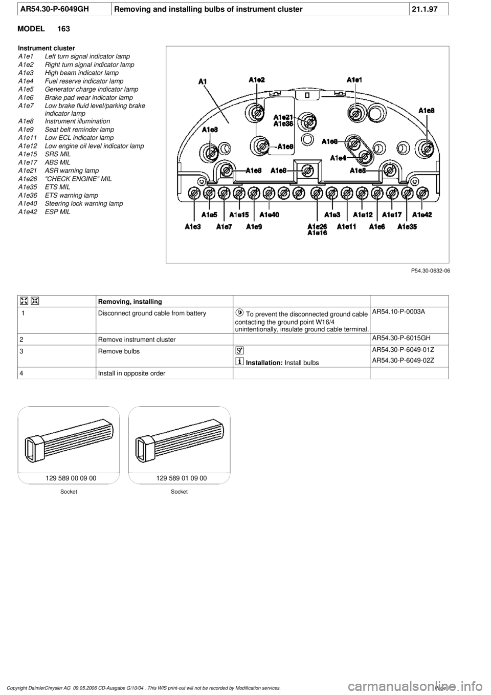
AR54.30-P-6049GH
Removing and installing bulbs of instrument cluster
21.1.97
MODEL
163
P54.30-0632-06
Instrument cluster
A1e1
Left turn signal indicator lamp
A1e2
Right turn signal indicator lamp
A1e3
High beam indicator lamp
A1e4
Fuel reserve indicator lamp
A1e5
Generator charge indicator lamp
A1e6
Brake pad wear indicator lamp
A1e7
Low brake fluid level/parking brake
indicator lamp
A1e8
Instrument illumination
A1e9
Seat belt reminder lamp
A1e11
Low ECL indicator lamp
A1e12
Low engine oil level indicator lamp
A1e15
SRS MIL
A1e17
ABS MIL
A1e21
ASR warning lamp
A1e26
"CHECK ENGINE" MIL
A1e35
ETS MIL
A1e36
ETS warning lamp
A1e40
Steering lock warning lamp
A1e42
ESP MIL
Removing, installing
1
Disconnect ground cable from battery
To prevent the disconnected ground cable
contacting the ground point W16/4
unintentionally, insulate ground cable terminal.
AR54.10-P-0003A
2
Remove instrument cluster
AR54.30-P-6015GH
3
Remove bulbs
AR54.30-P-6049-01Z
Installation:
Install bulbs
AR54.30-P-6049-02Z
4
Install in opposite order
129 589 00 09 00 129 589 01 09 00
Socket
Socket
Copyright DaimlerChrysler AG 09.05.2006 CD-Ausgabe G/10/04 . This WIS print-out will not be recorde
d by Modification services.
Page 1
Page 3498 of 4133

AF54.30-P-8400A
Instrument cluster indicates: Oil sensor defective, oil level below min. or oil level
above max. with engine running and at operating temperature. No DTC stored.
19.5.98
MODEL
129.0, 163.1, 202.0, 208.3 /4, 210.0 /2 /6, 220.0 /1 with ENGINE 112
MODEL
129.0, 163.1, 202.0, 208.3 /4, 210.0 /2, 220.0 /1 with ENGINE 113
Damage code
Cause
Remedy
54 201 90
Oil low, connector defective or coding error
1
Shut off engine and wait 2 min. (key
position 0)
Instrument cluster indicates oil sensor
defective, oil level below min. or oil level
above max. with engine warm and running.
No DTC stored in DTC memory!
2
Check oil level with oil dipstick
3
Check oil level on instrument cluster:
- Key in steering wheel lock position 2,
engine not running
- Wait until - - - - - - appears on
instrument cluster
- When this is displayed press the reset
button for the tripodometer twice within
1 sec. (display appears only after
expiration of a waiting time (max. 30
min.) depending on engine oil
temperature)
Oil level is at bottom mark on oil dipstick
and instrument cluster indicates:
-1L
, -
1,5L
or -2L
#
4
Add quantity of oil indicated on
instrument cluster display and repeat
test.
Oil level at upper mark on dipstick and
instrument cluster indicates either oil level
okay or -1L
, -
1,5L
, -2L
#
5
Recode instrument cluster
AF54.30-P-8600A
Problem still present
#
6
Check cable to oil sensor, oil sensor
connectors, control module and fuse
box (see wiring diagram) for good contact
Copyright DaimlerChrysler AG 05.06.2006 CD-Ausgabe G/10/04 . This WIS print-out will not be recorde
d by Modification services.
Page 1
Page 3722 of 4133
BT27.10-P-0006-01W
Oil pan and overflow tube modified
k
TRANSMISSION
722.901
P27.10-2139-06
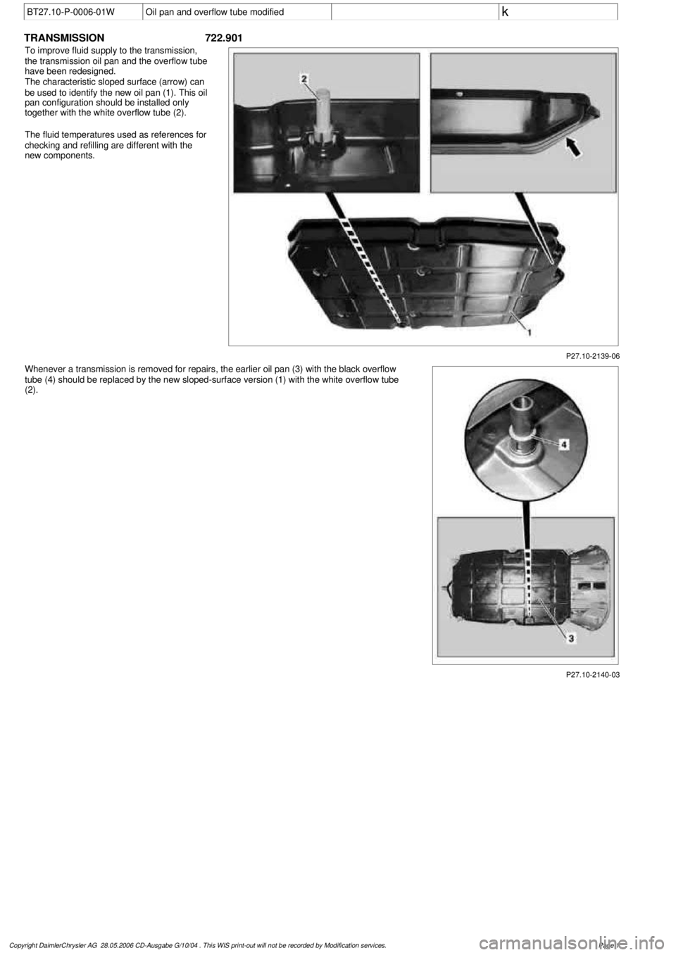
To improve fluid supply to the transmission,
the transmission oil pan and the overflow tube
have been redesigned.
The characteristic sloped surface (arrow) can
be used to identify the new oil pan (1). This oil
pan configuration should be installed only
together with the white overflow tube (2).
The fluid temperatures used as references for
checking and refilling are different with the
new components.
Whenever a transmission is removed for repairs, the earlier oil pan (3) with the black overflow
tube (4) should be replaced by the new sloped-surface version (1) with the white overflow tube
(2).
P27.10-2140-03
Copyright DaimlerChrysler AG 28.05.2006 CD-Ausgabe G/10/04 . This WIS print-out will not be recorde
d by Modification services.
Page 1
Page 3740 of 4133
AR03.10-P-7311-01V
Measure end clearance of piston rings
Modification notes
12.6.02
Value in line 1001 for Engine 113.967 modified from
0.012...0.060 to 0.033...0.07 and from 0010...0.030 to
0.01...0.04
Value in BE03.10-P-1001-05B for Engine
113.967 modified
*BE03.10-P-1001-05B
Test values for piston rings
Number
Designation
Engine 112.910/
911/912
Engine 112.920/
921/922/923/940/
941/942/943/944/
945/946/947/948/
960,
113.940/941/942/
943
Engine 113.944/
980/981/982/984
BE03.10-P-1001-05B
Vertical clearance of
piston ring
Groove 1
mm
0,012...0,0600,012...0,0600,012...0,060
Groove 2
mm
0,010...0,0300,010...0,0300,010...0,030
Test values for piston rings
Number
Designation
Engine 113.960/
961/962/963/965/
968
Engine
113.967
BE03.10-P-1001-05B
Vertical clearance of
piston ring
Groove 1
mm
0,012...0,0600,033...0,070
Groove 2
mm
0,010...0,030
0,01...0,04
Commercially available tools
(see Workshop Equipment Manual)
Number
Designation
Make (e.g.)
Order number
WH58.30-Z-1008-12A
Feeler gage
Stiefelmayer
D-73734 Esslingen
59
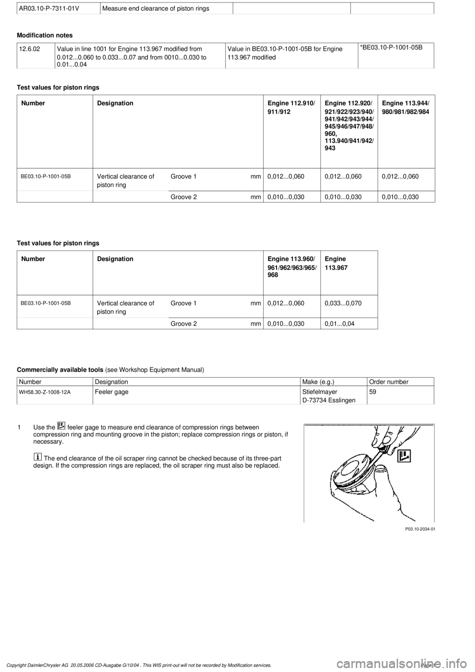
P03.10-2034-01
1
Use the
feeler gage to measure end clearance of compression rings between
compression ring and mounting groove in the piston; replace compression rings or piston, if
necessary.
The end clearance of the oil scraper ring cannot be checked because of its three-part
design. If the compression rings are replaced, the oil scraper ring must also be replaced.
Copyright DaimlerChrysler AG 20.05.2006 CD-Ausgabe G/10/04 . This WIS print-out will not be recorde
d by Modification services.
Page 1