1997 MERCEDES-BENZ ML350 check oil
[x] Cancel search: check oilPage 2327 of 4133
Model 215.373/375
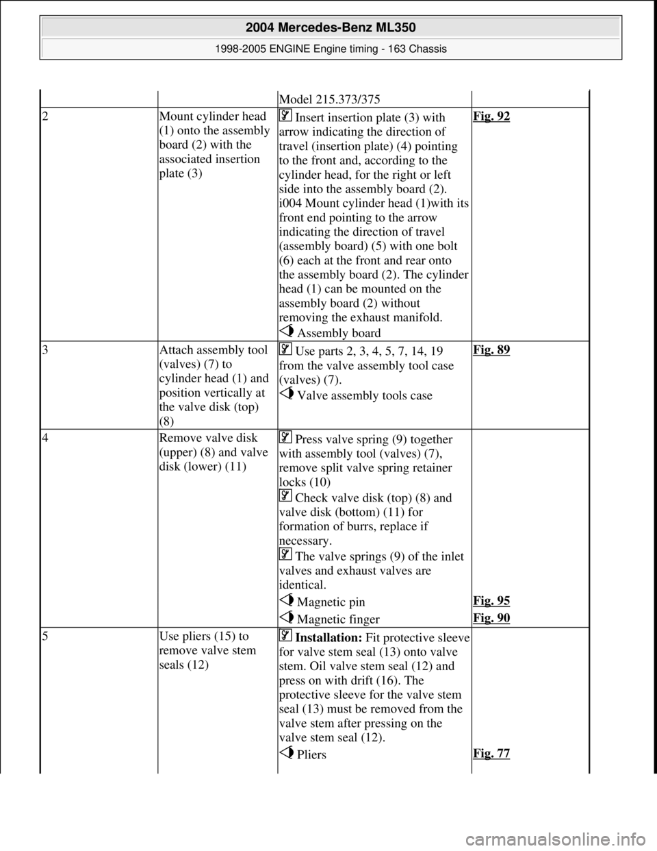
2Mount cylinder head
(1) onto the assembly
board (2) with the
associated insertion
plate (3) Insert insertion plate (3) with
arrow indicating the direction of
travel (insertion pl ate) (4) pointing
to the front and, according to the
cylinder head, for the right or left
side into the assembly board (2).
i004 Mount cylinder head (1)with its
front end pointing to the arrow
indicating the dir ection of travel
(assembly board) (5) with one bolt
(6) each at the front and rear onto
the assembly board (2). The cylinder
head (1) can be mounted on the
assembly board (2) without
removing the exhaust manifold.
Assembly boardFig. 92
3Attach assembly tool
(valves) (7) to
cylinder head (1) and
position vertically at
the valve disk (top)
(8) Use parts 2, 3, 4, 5, 7, 14, 19
from the valve assembly tool case
(valves) (7).
Valve assembly tools caseFig. 89
4Remove valve disk
(upper) (8) and valve
disk (lower) (11) Press valve spring (9) together
with assembly tool (valves) (7),
remove split valve spring retainer
locks (10)
Check valve disk (top) (8) and
valve disk (bottom) (11) for
formation of burrs, replace if
necessary.
The valve springs (9) of the inlet
valves and exhaust valves are
identical.
Magnetic pinFig. 95
Magnetic fingerFig. 90
5Use pliers (15) to
remove valve stem
seals (12) Installation: Fit protective sleeve
for valve stem seal (13) onto valve
stem. Oil valve stem seal (12) and
press on with drift (16). The
protective sleeve for the valve stem
seal (13) must be removed from the
valve stem after pressing on the
valve stem seal (12).
PliersFig. 77
2004 Mercedes-Benz ML350
1998-2005 ENGINE Engine timing - 163 Chassis
me
Saturday, October 02, 2010 3:39:38 PMPage 86 © 2006 Mitchell Repair Information Company, LLC.
Page 2335 of 4133
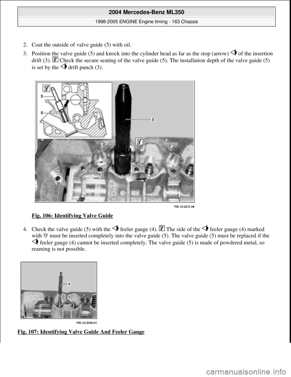
2. Coat the outside of valve guide (5) with oil.
3. Position the valve guide (5) and knock into the cylinder head as far as the stop (arrow) of the insertion
drift (3). Check the secure seati ng of the valve guide (5). The instal lation depth of the valve guide (5)
is set by the drift punch (3).
Fig. 106: Identifying Valve Guide
4. Check the valve guide (5) with the feeler gauge (4). The side of the feeler gauge (4) marked
with '0' must be inserted completely into the valve gui de (5). The valve guide (5) must be replaced if the
feeler gauge (4) cannot be insert ed completely. The valve guide (5) is made of powdered metal, so
reaming is not possible.
Fig. 107: Identifying Valve Guide And Feeler Gauge
2004 Mercedes-Benz ML350
1998-2005 ENGINE Engine timing - 163 Chassis
me
Saturday, October 02, 2010 3:39:38 PMPage 94 © 2006 Mitchell Repair Information Company, LLC.
Page 2356 of 4133
1998-2005 ENGINE
Complete engine - 163 Chassis
GENERAL INFORMATION
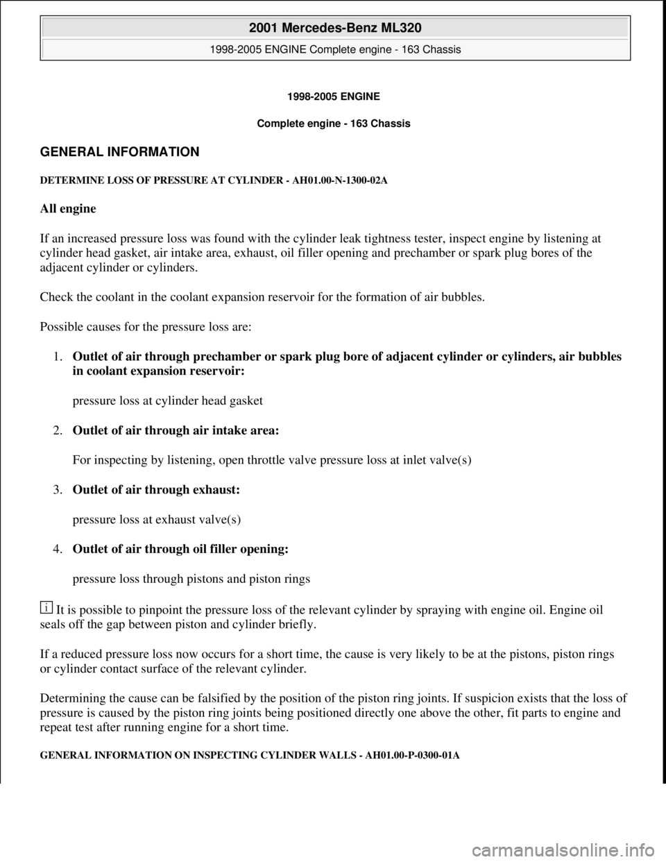
DETERMINE LOSS OF PR ESSURE AT CYLINDER - AH01.00-N-1300-02A
All engine
If an increased pressure loss was found with the cylinde r leak tightness tester, inspect engine by listening at
cylinder head gasket, air intake area, exhaust, oil fi ller opening and prechamber or spark plug bores of the
adjacent cylinder or cylinders.
Check the coolant in the coolant expansion reservoir for the formation of air bubbles.
Possible causes for the pressure loss are: 1. Outlet of air through prechamber or spark plug bo re of adjacent cylinder or cylinders, air bubbles
in coolant expansion reservoir:
pressure loss at cylinder head gasket
2. Outlet of air through air intake area:
For inspecting by listening, open throttle valve pressure loss at inlet valve(s)
3. Outlet of air through exhaust:
pressure loss at exhaust valve(s)
4. Outlet of air through oil filler opening:
pressure loss through pistons and piston rings
It is possible to pinpoint the pressure loss of the rele vant cylinder by spraying with engine oil. Engine oil
seals off the gap between piston and cylinder briefly.
If a reduced pressure loss now occurs for a short time, th e cause is very likely to be at the pistons, piston rings
or cylinder contact surface of the relevant cylinder.
Determining the cause can be falsified by the position of th e piston ring joints. If suspicion exists that the loss o
f
pressure is caused by the piston ring joints being positioned directly one above the other, fit parts to engine and
repeat test after running engine for a short time.
GENERAL INFORMATION ON INSPECTING CYLINDER WALLS - AH01.00-P-0300-01A
2001 Mercedes-Benz ML320
1998-2005 ENGINE Complete engine - 163 Chassis
2001 Mercedes-Benz ML320
1998-2005 ENGINE Complete engine - 163 Chassis
me
Saturday, October 02, 2010 3:17:55 PMPage 1 © 2006 Mitchell Repair Information Company, LLC.
me
Saturday, October 02, 2010 3:18:01 PMPage 1 © 2006 Mitchell Repair Information Company, LLC.
Page 2414 of 4133
Oil pan
Fuel distributor
Fuel distributor
Exhaust manifold
when engine is
running. Risk of
injury caused by
contusions and burns
during starting
procedure or when
working near the
engine as it is
running
Check for leaks with
engine runningDo not touch hot or rotating parts.
44Read out fault
memory and eraseStored faults which can result from cables
being disconnected or from simulation during
removal and installation or test work, have to
be processed and erased in the fault memories
after completing the work: ?
Diagnosis Manual Volume 2 Index 0:
Connecting and using test equipment.
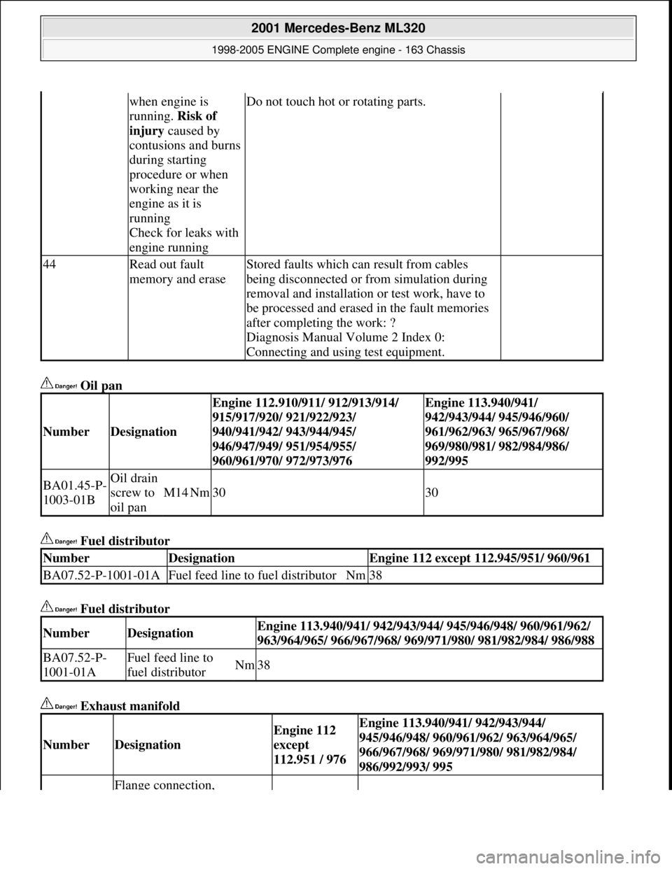
NumberDesignation
Engine 112.910/911/ 912/913/914/
915/917/920/ 921/922/923/
940/941/942/ 943/944/945/
946/947/949/ 951/954/955/
960/961/970/ 972/973/976Engine 113.940/941/
942/943/944/ 945/946/960/
961/962/963/ 965/967/968/
969/980/981/ 982/984/986/
992/995
BA01.45-P-
1003-01BOil drain
screw to
oil pan
M14Nm3030
NumberDesignationEngine 112 except 112.945/951/ 960/961
BA07.52-P-1001-01AFuel feed line to fuel distributorNm38
NumberDesignationEngine 113.940/941/ 942/943/944/ 945/946/948/ 960/961/962/
963/964/965/ 966/967/968/ 969/971/ 980/ 981/982/984/ 986/988
BA07.52-P-
1001-01AFuel feed line to
fuel distributorNm38
NumberDesignation
Engine 112
except
112.951 / 976Engine 113.940/941/ 942/943/944/
945/946/948/ 960/961/962/ 963/964/965/
966/967/968/ 969/971/980/ 981/982/984/
986/992/993/ 995
Flange connection,
2001 Mercedes-Benz ML320
1998-2005 ENGINE Complete engine - 163 Chassis
me
Saturday, October 02, 2010 3:17:56 PMPage 58 © 2006 Mitchell Repair Information Company, LLC.
Page 2433 of 4133
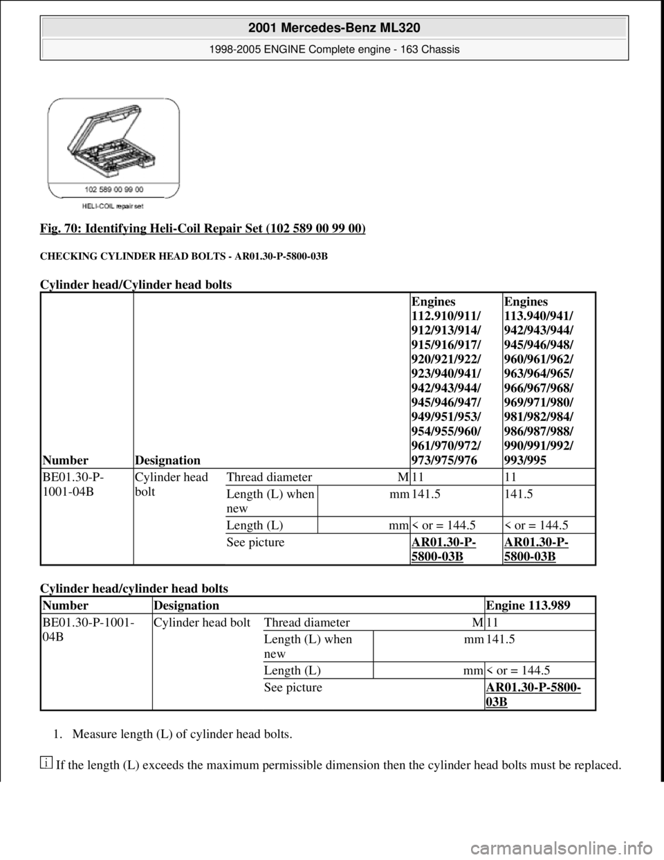
Fig. 70: Identifying Heli-Coil Repair Set (102 589 00 99 00)
CHECKING CYLINDER HEAD BOLTS - AR01.30-P-5800-03B
Cylinder head/Cylinder head bolts
Cylinder head/cyl inder head bolts
1. Measure length (L) of cylinder head bolts.
If the length (L) exceeds the maximu m permissible dimension then the cyli nder head bolts must be replaced.
NumberDesignation
Engines
112.910/911/
912/913/914/
915/916/917/
920/921/922/
923/940/941/
942/943/944/
945/946/947/
949/951/953/
954/955/960/
961/970/972/
973/975/976Engines
113.940/941/
942/943/944/
945/946/948/
960/961/962/
963/964/965/
966/967/968/
969/971/980/
981/982/984/
986/987/988/
990/991/992/
993/995
BE01.30-P-
1001-04BCylinder head
boltThread diameterM1111
Length (L) when
newmm141.5141.5
Length (L)mm< or = 144.5< or = 144.5
See pictureAR01.30-P-
5800-03B
AR01.30-P-
5800-03B
NumberDesignationEngine 113.989
BE01.30-P-1001-
04BCylinder head boltThread diameterM11
Length (L) when
newmm141.5
Length (L)mm< or = 144.5
See pictureAR01.30-P-5800-
03B
2001 Mercedes-Benz ML320
1998-2005 ENGINE Complete engine - 163 Chassis
me
Saturday, October 02, 2010 3:17:56 PMPage 77 © 2006 Mitchell Repair Information Company, LLC.
Page 2443 of 4133
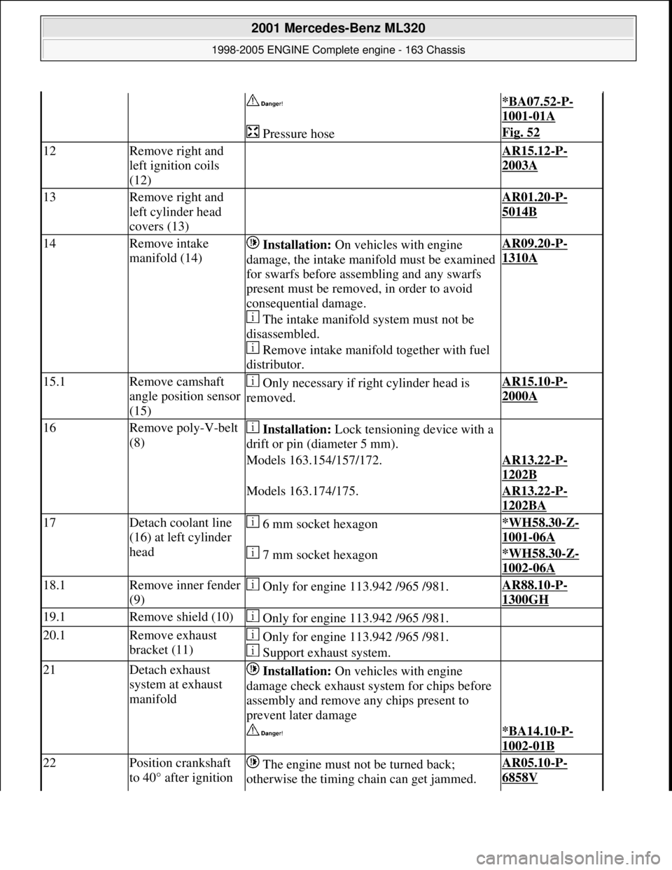
*BA07.52-P-
1001-01A
Pressure hoseFig. 52
12Remove right and
left ignition coils
(12) AR15.12-P-
2003A
13Remove right and
left cylinder head
covers (13) AR01.20-P-
5014B
14Remove intake
manifold (14) Installation: On vehicles with engine
damage, the intake manifold must be examined
for swarfs before assembling and any swarfs
present must be removed, in order to avoid
consequential damage.
The intake manifold system must not be
disassembled.
Remove intake manifold together with fuel
distributor.AR09.20-P-
1310A
15.1Remove camshaft
angle position sensor
(15) Only necessary if right cylinder head is
removed.AR15.10-P-
2000A
16Remove poly-V-belt
(8) Installation: Lock tensioning device with a
drift or pin (diameter 5 mm).
Models 163.154/157/172.AR13.22-P-
1202B
Models 163.174/175.AR13.22-P-
1202BA
17Detach coolant line
(16) at left cylinder
head 6 mm socket hexagon*WH58.30-Z-
1001-06A
7 mm socket hexagon*WH58.30-Z-
1002-06A
18.1Remove inner fender
(9) Only for engine 113.942 /965 /981.AR88.10-P-
1300GH
19.1Remove shield (10) Only for engine 113.942 /965 /981.
20.1Remove exhaust
bracket (11) Only for engine 113.942 /965 /981.
Support exhaust system.
21Detach exhaust
system at exhaust
manifold Installation: On vehicles with engine
damage check exhaust sy stem for chips before
assembly and remove any chips present to
prevent later damage
*BA14.10-P-
1002-01B
22Position crankshaft
to 40° after ignition The engine must not be turned back;
otherwise the timing chain can get jammed. AR05.10-P-
6858V
2001 Mercedes-Benz ML320
1998-2005 ENGINE Complete engine - 163 Chassis
me
Saturday, October 02, 2010 3:17:57 PMPage 87 © 2006 Mitchell Repair Information Company, LLC.
Page 2444 of 4133
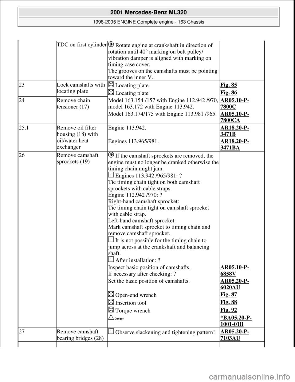
TDC on first cylinder Rotate engine at cra nkshaft in direction of
rotation until 40° marking on belt pulley/
vibration damper is al igned with marking on
timing case cover.
The grooves on the camshafts must be pointing
toward the inner V.
23Lock camshafts with
locating plate Locating plateFig. 85
Locating plateFig. 86
24Remove chain
tensioner (17)Model 163.154 /157 with Engine 112.942 /970,
model 163.172 with Engine 113.942.AR05.10-P-
7800C
Model 163.174/175 with Engine 113.981 /965.AR05.10-P-
7800CA
25.1Remove oil filter
housing (18) with
oil/water heat
exchangerEngine 113.942.AR18.20-P-
3471B
Engines 113.965/981.AR18.20-P-
3471BA
26Remove camshaft
sprockets (19) If the camshaft sprockets are removed, the
engine must no longer be cranked otherwise the
timing chain might jam.
Engines 113.942 /965/981: ?
Tie timing chain tight on both camshaft
sprockets with cable straps.
Engine 112.942 /970: ?
Right-hand camshaft sprocket:
Tie timing chain tight on camshaft sprocket
with cable strap.
Left-hand camshaft sprocket:
Mark camshaft sprocket to timing chain and
remove camshaft sprocket.
It is not possible for the timing chain to
jump across at the crankshaft and balancing
shaft.
After installation: ?
Inspect basic positi on of camshafts.
If necessary after checking: ?AR05.10-P-
6858V
Set the basic position of camshafts.AR05.20-P-
6020AU
Open-end wrenchFig. 87
Insertion toolFig. 88
Torque wrenchFig. 92
*BA05.20-P-
1001-01B
27Remove camshaft
bearing bridges (28) Observe slackening and tightening pattern!AR05.20-P-
7103AU
2001 Mercedes-Benz ML320
1998-2005 ENGINE Complete engine - 163 Chassis
me
Saturday, October 02, 2010 3:17:57 PMPage 88 © 2006 Mitchell Repair Information Company, LLC.
Page 2445 of 4133
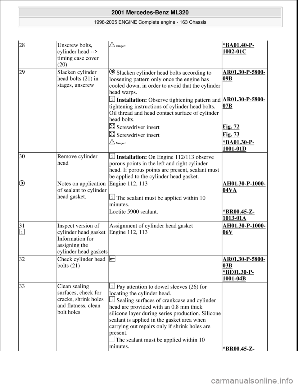
28Unscrew bolts,
cylinder head -->
timing case cover
(20) *BA01.40-P-
1002-01C
29Slacken cylinder
head bolts (21) in
stages, unscrew Slacken cylinder head bolts according to
loosening pattern only once the engine has
cooled down, in order to avoid that the cylinder
head warps.AR01.30-P-5800-
09B
Installation: Observe tightening pattern and
tightening instructions of cylinder head bolts.
Oil thread and head cont act surface of cylinder
head bolts.AR01.30-P-5800-
07B
Screwdriver insertFig. 72
Screwdriver insertFig. 73
*BA01.30-P-
1001-01D
30Remove cylinder
head Installation: On Engine 112/113 observe
porous points in the le ft and right cylinder
head. If porous points are present, sealant must
be applied to the cylinder head gasket.
Notes on application
of sealant to cylinder
head gasket.Engine 112, 113AH01.30-P-1000-
04VA
The sealant must be applied within 10
minutes.
Loctite 5900 sealant.*BR00.45-Z-
1013-01A
31
Inspect version of
cylinder head gasket
Information for
assigning the
cylinder head gasketsAssignment of cylinder head gasket
Engine 112, 113AH01.30-P-1000-
06V
32Check cylinder head
bolts (21) AR01.30-P-5800-
03B
*BE01.30
-P-
1001-04B
33Clean sealing
surfaces, check for
cracks, shrink holes
and flatness, clean
bolt holes Pay attention to dowel sleeves (26) for
locating the cylinder head.
Sealing surfaces of crankcase and cylinder
head are provided with an 0.8 mm thick
silicone layer during se ries production. Silicone
sealant is applied in the gasket area when
carrying out repairs only if shrink holes are
present.
The sealant must be applied within 10
minutes.
*BR00.45-Z-
2001 Mercedes-Benz ML320
1998-2005 ENGINE Complete engine - 163 Chassis
me
Saturday, October 02, 2010 3:17:57 PMPage 89 © 2006 Mitchell Repair Information Company, LLC.