1997 MERCEDES-BENZ ML350 check oil
[x] Cancel search: check oilPage 2156 of 4133
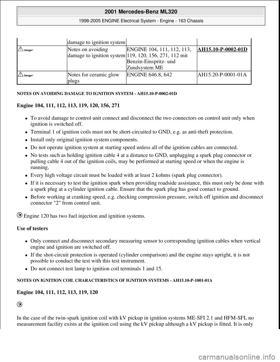
NOTES ON AVOIDING DAMAGE TO IGNITION SYSTEM - AH15.10-P-0002-01D
Engine 104, 111, 112, 113, 119, 120, 156, 271
To avoid damage to control unit connect and disconnect the two connectors on control unit only when
ignition is switched off.
Terminal 1 of ignition coils must not be short-circuited to GND, e.g. as anti-theft protection.
Install only original ignition system components.
Do not operate ignition system at starting speed unless all of the ignition cables are connected.
No tests such as holding ignition cable 4 at a distance to GND, unplugging a spark plug connector or
pulling cable 4 out of the ignition coils, may be performed at starting speed or when the engine is
running.
Every high voltage circuit must be loaded with at least 2 kohms (spark plug connector).
If it is necessary to test the ignition spark when providing roadside assistance, this must only be done with
a spark plug at a cylinder ignition cable. Ensure that the spark plug has good contact to ground.
Before working at cranking speed, e.g. checking compression pressure, switch off ignition and disconnect
connector "2" from control unit.
Engine 120 has two fuel injection and ignition systems.
Use of testers
Only connect and disconnect secondary measuring sensor to corresponding ignition cables when vertical
engine and ignition are switched off.
If the shot-circuit protection is operated (cylinder comparison) and the engine stays upright, it is not
possible to conduct the test with this test instrument.
Do not connect test lamp to ignition coil terminals 1 and 15.
NOTES ON IGNITION COIL CHARACTERISTICS OF IGNITION SYSTEMS - AH15.10-P-1001-01A
Engine 104, 111, 112, 113, 119, 120
In the case of the twin-spark ignition coil with kV pickup in ignition systems ME-SFI 2.1 and HFM-SFI, no
measurement facilit
y exists at the ignition coil using the kV pickup although a kV pickup is fitted. It is only
damage to ignition system
Notes on avoiding
damage to ignition systemENGINE 104, 111, 112, 113,
119, 120, 156, 271, 112 mit
Benzin-Einspritz- und
Zundsystem MEAH15.10-P-0002-01D
Notes for ceramic glow
plugsENGINE 646.8, 642AH15.20-P-0001-01A
2001 Mercedes-Benz ML320
1998-2005 ENGINE Electrical System - Engine - 163 Chassis
me
Saturday, October 02, 2010 3:18:54 PMPage 2 © 2006 Mitchell Repair Information Company, LLC.
Page 2171 of 4133
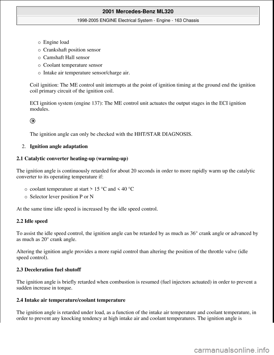
Engine load
Crankshaft position sensor
Camshaft Hall sensor
Coolant temperature sensor
Intake air temperature sensor/charge air.
Coil ignition: The ME control unit interrupts at the point of ignition timing at the ground end the ignition
coil primary circuit of the ignition coil.
ECI ignition system (engine 137): The ME control unit actuates the output stages in the ECI ignition
modules.
The ignition angle can only be checked with the HHT/STAR DIAGNOSIS.
2.Ignition angle adaptation
2.1 Catalytic converter heating-up (warming-up)
The ignition angle is continuously retarded for about 20 seconds in order to more rapidly warm up the catalytic
converter to its operating temperature if:
coolant temperature at start > 15 °C and < 40 °C
Selector lever position P or N
At the same time idle speed is increased by the idle speed control.
2.2 Idle speed
To assist the idle speed control, the ignition angle can be retarded by as much as 36° crank angle or advanced by
as much as 20° crank angle.
Altering the ignition angle provides a more rapid control than altering the position of the throttle valve (idle
speed control).
2.3 Deceleration fuel shutoff
The ignition angle is briefly retarded when combustion is resumed (fuel injectors actuated) in order to prevent a
sudden increase in torque.
2.4 Intake air temperature/coolant temperature
The ignition angle is retarded under load, as a function of the intake air temperature and coolant temperature, in
order to prevent an
y knocking tendency at high intake air and coolant temperatures. The ignition angle is
2001 Mercedes-Benz ML320
1998-2005 ENGINE Electrical System - Engine - 163 Chassis
me
Saturday, October 02, 2010 3:18:54 PMPage 17 © 2006 Mitchell Repair Information Company, LLC.
Page 2226 of 4133
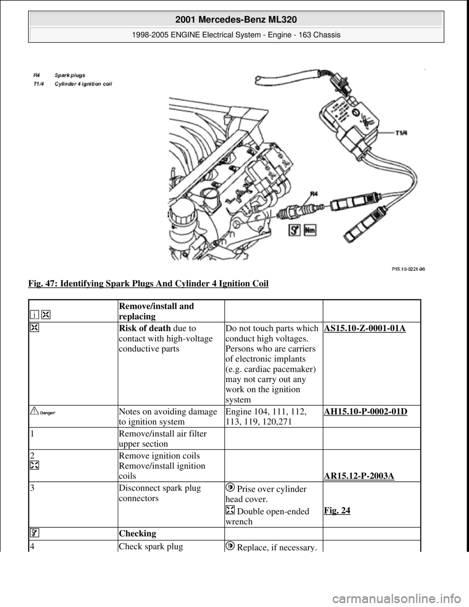
Fig. 47: Identifying Spark Plugs And Cylinder 4 Ignition Coil
Remove/install and
replacing
Risk of death due to
contact with high-voltage
conductive partsDo not touch parts which
conduct high voltages.
Persons who are carriers
of electronic implants
(e.g. cardiac pacemaker)
may not carry out any
work on the ignition
systemAS15.10-Z-0001-01A
Notes on avoiding damage
to ignition systemEngine 104, 111, 112,
113, 119, 120,271AH15.10-P-0002-01D
1Remove/install air filter
upper section
2
Remove ignition coils
Remove/install ignition
coils
AR15.12-P-2003A
3Disconnect spark plug
connectors Prise over cylinder
head cover.
Double open-ended
wrenchFig. 24
Checking
4Check spark plug Replace, if necessary.
2001 Mercedes-Benz ML320
1998-2005 ENGINE Electrical System - Engine - 163 Chassis
me
Saturday, October 02, 2010 3:18:55 PMPage 72 © 2006 Mitchell Repair Information Company, LLC.
Page 2233 of 4133

11
Check oil level approx. 5 min. after switching
off warm engine
Insert oil dipstick up to the stop and keep
to a residence time of at least 3 seconds.
Model 163, 210 with Engine 612
*BE18.00-P-1001-02B
Model 203, Model 209 with Engine 612
On Model 203, Model 209 after oil level
check pay attention to correct seating of the
cap, otherwise it could result in engine
damage.
Only Model 203:
Up to engine end number: 134 163 oil level
MAX. 135
mm,
MIN 110
mm.
As of engine end number: 134 164 oil level
MAX. 124,5
mm,
MIN 99,5
mm.
Measuring rod
*120589072100
12
Install trim panel of cylinder head cover
AR01.20-P-5014-02B
*BA01.20-P-1002-01A
*BA01.20-P-1003-01A
Test values for engine lubrication - general
Number
Designation
Engine
612.961
Engine
612.963
BE18.00-P-1001-02B
Dipstick marking
Color red
t
1
Color black
t
2
Color green
t
3
Color gentian blue
t
4
Numbers on handle
Number
6020760206
Round handle
Color
--
Bottle opener-shaped
handle
Color
11
Designation
Engine
612.961/962/
963/965/966,
613.961
Engine
612.967
Engine
612.990
BA01.45-P-1003-01A
Oil drain plug at oil pan
M12
Nm
---
M14
Nm
303030
Engine lubrication, oil filter
Number
Designation
Engine
612.961/962/
963/967/990,
613.960/961
BA18.20-P-1002-01G
Screw cap at oil filter
Nm
25
Crankcase ventilation, cylinder head cover
Number
Designation
Engine
612.961/
962/967
Engine
612.963
Engine
612.990
Copyright DaimlerChrysler AG 20.05.2006 CD-Ausgabe G/10/04 . This WIS print-out will not be recorde
d by Modification services.
Page 2
Page 2239 of 4133

AF07.00-P-9000B
Engine runs rough, surges or does not turn over
29.4.02
ENGINE
611 in MODEL 203, 202, 210
ENGINE
612 in MODEL 163, 203, 210, 209
ENGINE
613 in MODEL 210, 220
ENGINE
628 in MODEL 163, 220, 211
ENGINE
646 in MODEL 203, 211
ENGINE
647 in MODEL 211
ENGINE
648 in MODEL 220, 211
ENGINE
668 in MODEL 168
ENGINE
612, 628 in MODEL 463
Modification notes
23.3.01
Supersedes STIP 07.16-014 dated 11.12.00
Damage code
Cause
Remedy
07 206 D5
High-pressure pump
To verify whether high pressure pump is
damaged.
#
High pressure pump of common rail
injection system is damaged mechanically.
1
Remove/install/replace high pressure
pump.
When the high pressure pump of the common
rail injection system is damaged metal chips
and/or damage to the pump drive (timing
drive) can occur due to contamination of the
injection system components.
2
Turn high pressure pump by hand with
driver.
If mechanical resistance can be felt,
perform the following tests. Clarify additional
work with ESKULAB by specifying repair work:
#
3
Check driver of high pressure pump or
mount in sprocket for damage (visual
check).
If high pressure pump is locked:
#
4
Check timing
5
Check timing drive for damage.
In each case:
#
6
Remove/install/replace timing chain.
If timing deviates by a crankshaft angle of
more than 20 degrees (corresponding to one
tooth skipped):
#
7
Check pressure loss.
8
Open low pressure connection on high
pressure pump return (plastic line in
area of pressure regulator valve) and
check connection point in rail for chips.
If chips are present when checking
injection system:
#
9
Thoroughly clean all fuel low pressure
lines as well as feed and return lines.
Flush and blow out with compressed air.
10
Remove fuel preheater and fuel filter
with filter housing, replace.
Fuel preheater is only installed in models
202, 203 and 163.
11
Remove/install/replace fuel cooler at
vehicle and engine end.
Not installed in model 210 up to 6/99 and
model 168.
12
Remove fuel tank, replace.
On engine 628:
#
13
Remove/install/replace electric supply
pump.
14
Remove/install/replace injectors, rail
(including pressure regulation valve and
rail pressure sensor), high pressure
lines and injector leak oil rail.*
Copyright DaimlerChrysler AG 28.05.2006 CD-Ausgabe G/10/04 . This WIS print-out will not be recorde
d by Modification services.
Page 1
Page 2296 of 4133
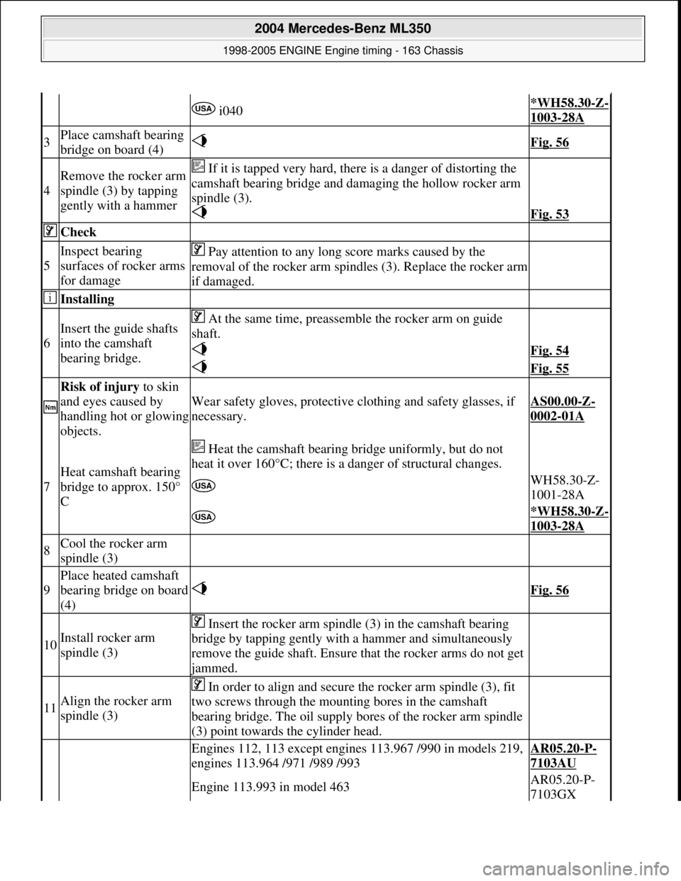
i040*WH58.30-Z-
1003-28A
3Place camshaft bearing
bridge on board (4) Fig. 56
4
Remove the rocker arm
spindle (3) by tapping
gently with a hammer If it is tapped very hard, th ere is a danger of distorting the
camshaft bearing bridge and da maging the hollow rocker arm
spindle (3).
Fig. 53
Check
5
Inspect bearing
surfaces of rocker arms
for damage Pay attention to any long score marks caused by the
removal of the rocker arm spindl es (3). Replace the rocker arm
if damaged.
Installing
6
Insert the guide shafts
into the camshaft
bearing bridge. At the same time, preassemble the rocker arm on guide
shaft.
Fig. 54
Fig. 55
Risk of injury to skin
and eyes caused by
handling hot or glowing
objects.
Wear safety gloves, protective cl othing and safety glasses, if
necessary.AS00.00-Z-
0002-01A
7
Heat camshaft bearing
bridge to approx. 150°
C
Heat the camshaft bearing bridge uniformly, but do not
heat it over 160°C; there is a danger of structural changes.
WH58.30-Z-
1001-28A
*WH58.30-Z-
1003-28A
8Cool the rocker arm
spindle (3)
9
Place heated camshaft
bearing bridge on board
(4) Fig. 56
10Install rocker arm
spindle (3)
Insert the rocker arm spindle (3) in the camshaft bearing
bridge by tapping gently with a hammer and simultaneously
remove the guide shaft. Ensure that the rocker arms do not get
jammed.
11Align the rocker arm
spindle (3)
In order to align and secure the rocker arm spindle (3), fit
two screws through the mount ing bores in the camshaft
bearing bridge. The oil supply bores of the rocker arm spindle
(3) point towards the cylinder head.
Engines 112, 113 except engines 113.967 /990 in models 219,
engines 113.964 /971 /989 /993AR05.20-P-
7103AU
Engine 113.993 in model 463AR05.20-P-
7103GX
2004 Mercedes-Benz ML350
1998-2005 ENGINE Engine timing - 163 Chassis
me
Saturday, October 02, 2010 3:39:38 PMPage 55 © 2006 Mitchell Repair Information Company, LLC.
Page 2315 of 4133
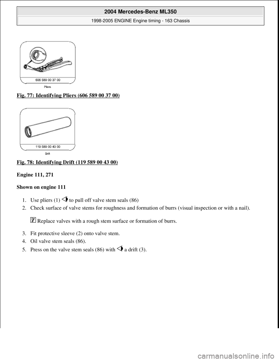
Fig. 77: Identifying Pl iers (606 589 00 37 00)
Fig. 78: Identifying Drift (119 589 00 43 00)
Engine 111, 271
Shown on engine 111
1. Use pliers (1) to pull of f valve stem seals (86)
2. Check surface of valve stems for roughness and format ion of burrs (visual inspection or with a nail).
Replace valves with a rough stem surface or formation of burrs.
3. Fit protective sleeve (2) onto valve stem.
4. Oil valve stem seals (86).
5. Press on the valve stem seal s (86) with a drift (3).
2004 Mercedes-Benz ML350
1998-2005 ENGINE Engine timing - 163 Chassis
me
Saturday, October 02, 2010 3:39:38 PMPage 74 © 2006 Mitchell Repair Information Company, LLC.
Page 2316 of 4133
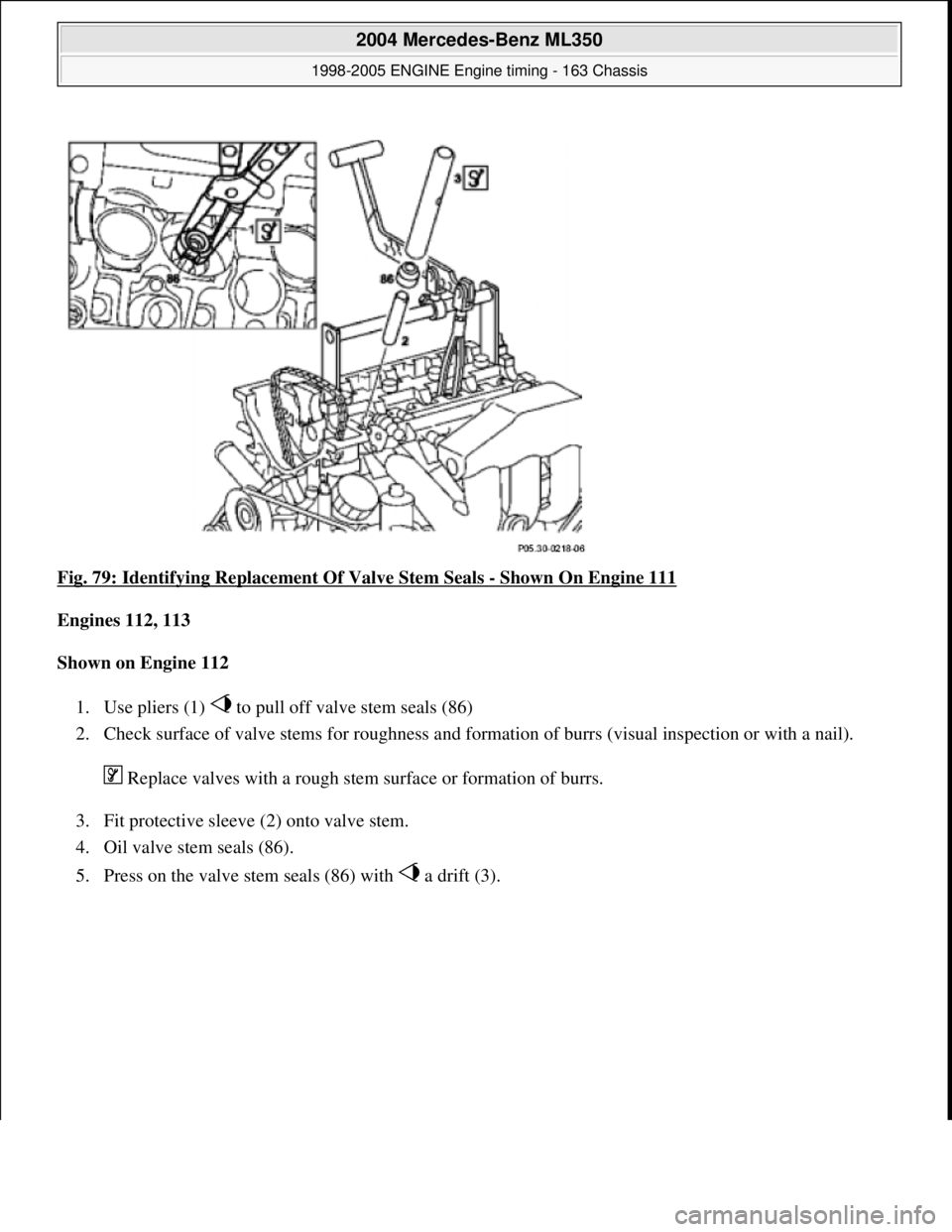
Fig. 79: Identifying Replacem ent Of Valve Stem Seals - Shown On Engine 111
Engines 112, 113
Shown on Engine 112
1. Use pliers (1) to pull of f valve stem seals (86)
2. Check surface of valve stems for roughness and format ion of burrs (visual inspection or with a nail).
Replace valves with a rough stem surface or formation of burrs.
3. Fit protective sleeve (2) onto valve stem.
4. Oil valve stem seals (86).
5. Press on the valve stem seal s (86) with a drift (3).
2004 Mercedes-Benz ML350
1998-2005 ENGINE Engine timing - 163 Chassis
me
Saturday, October 02, 2010 3:39:38 PMPage 75 © 2006 Mitchell Repair Information Company, LLC.