1997 MERCEDES-BENZ ML350 check oil
[x] Cancel search: check oilPage 1177 of 4133

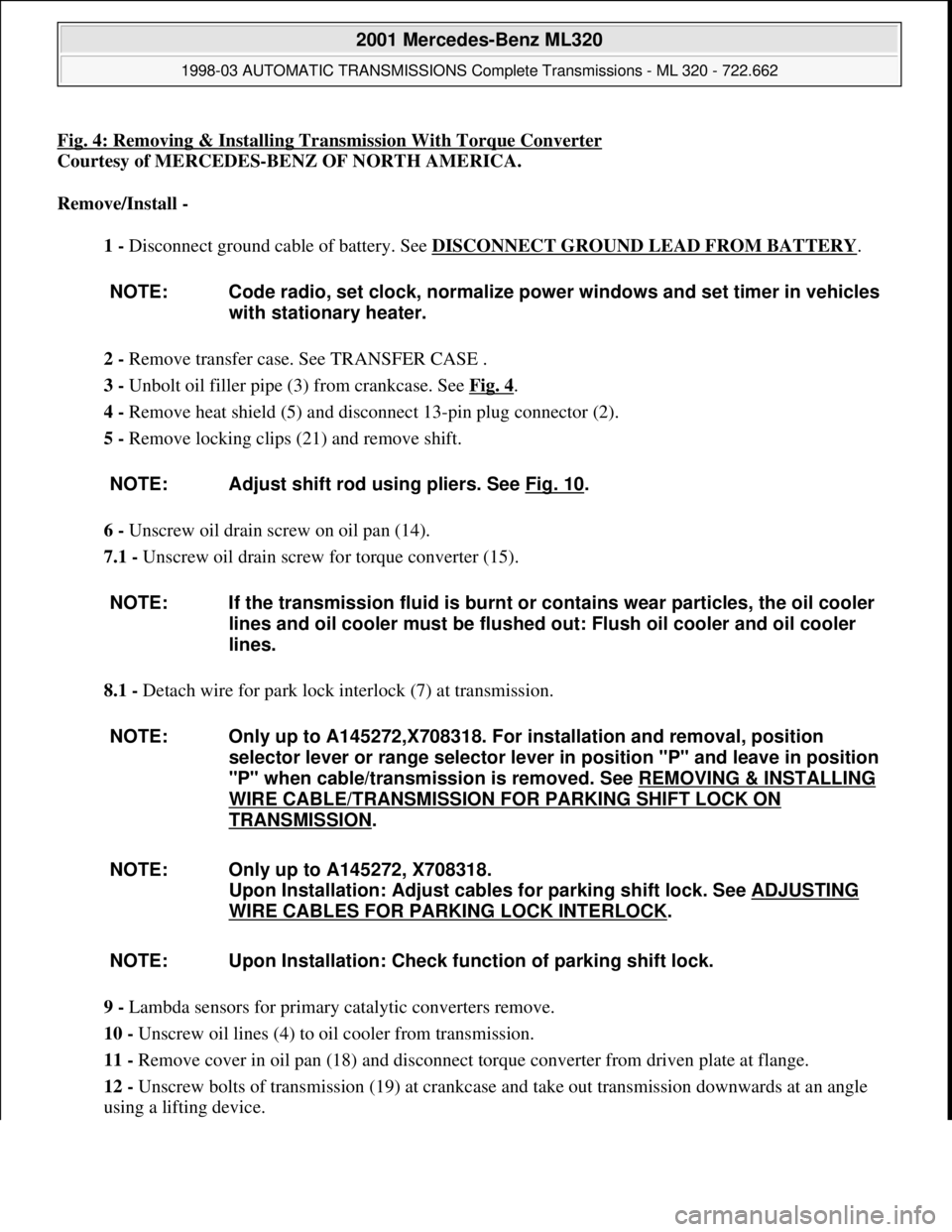
Fig. 4: Removing & Installing Transmission With Torque Converter
Courtesy of MERCEDES-BENZ OF NORTH AMERICA.
Remove/Install -
1 - Disconnect ground cable of battery. See DISCONNECT GROUND LEAD FROM BATTERY
.
2 - Remove transfer case. See TRANSFER CASE .
3 - Unbolt oil filler pipe (3) from crankcase. See Fig. 4
.
4 - Remove heat shield (5) and disconnect 13-pin plug connector (2).
5 - Remove locking clips (21) and remove shift.
6 - Unscrew oil drain screw on oil pan (14).
7.1 - Unscrew oil drain screw for torque converter (15).
8.1 - Detach wire for park lock interlock (7) at transmission.
9 - Lambda sensors for primary catalytic converters remove.
10 - Unscrew oil lines (4) to oil cooler from transmission.
11 - Remove cover in oil pan (18) and disconnect torque converter from driven plate at flange.
12 - Unscrew bolts of transmission (19) at crankcase and take out transmission downwards at an angle
using a lifting device. NOTE: Code radio, set clock, normalize power windows and set timer in vehicles
with stationary heater.
NOTE: Adjust shift rod using pliers. See Fig. 10
.
NOTE: If the transmission fluid is burnt or contains wear particles, the oil cooler
lines and oil cooler must be flushed out: Flush oil cooler and oil cooler
lines.
NOTE: Only up to A145272,X708318. For installation and removal, position
selector lever or range selector lever in position "P" and leave in position
"P" when cable/transmission is removed. See REMOVING & INSTALLING
WIRE CABLE/TRANSMISSION FOR PARKING SHIFT LOCK ON
TRANSMISSION.
NOTE: Only up to A145272, X708318.
Upon Installation: Adjust cables for parking shift lock. See ADJUSTING
WIRE CABLES FOR PARKING LOCK INTERLOCK.
NOTE: Upon Installation: Check function of parking shift lock.
2001 Mercedes-Benz ML320
1998-03 AUTOMATIC TRANSMISSIONS Complete Transmissions - ML 320 - 722.662
me
Saturday, October 02, 2010 3:15:25 PMPage 8 © 2006 Mitchell Repair Information Company, LLC.
Page 1467 of 4133

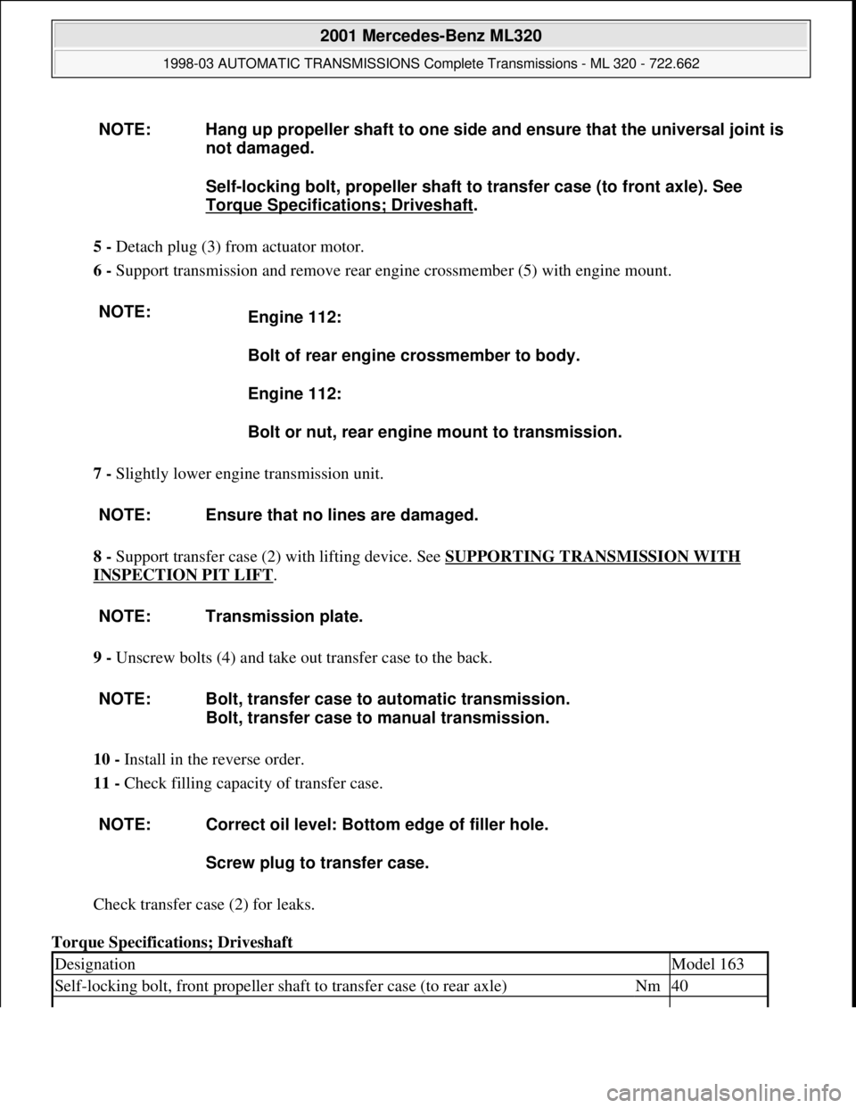
5 - Detach plug (3) from actuator motor.
6 - Support transmission and remove rear engine crossmember (5) with engine mount.
7 - Slightly lower engine transmission unit.
8 - Support transfer case (2) with lifting device. See SUPPORTING TRANSMISSION WITH
INSPECTION PIT LIFT.
9 - Unscrew bolts (4) and take out transfer case to the back.
10 - Install in the reverse order.
11 - Check filling capacity of transfer case.
Check transfer case (2) for leaks.
Torque Specifications; Driveshaft NOTE: Hang up propeller shaft to one side and ensure that the universal joint is
not damaged.
Self-locking bolt, propeller shaft to transfer case (to front axle). See
Torque Specifications; Driveshaft
.
NOTE:
Engine 112:
Bolt of rear engine crossmember to body.
Engine 112:
Bolt or nut, rear engine mount to transmission.
NOTE: Ensure that no lines are damaged.
NOTE: Transmission plate.
NOTE: Bolt, transfer case to automatic transmission.
Bolt, transfer case to manual transmission.
NOTE: Correct oil level: Bottom edge of filler hole.
Screw plug to transfer case.
DesignationModel 163
Self-locking bolt, front propeller shaft to transfer case (to rear axle)Nm40
2001 Mercedes-Benz ML320
1998-03 AUTOMATIC TRANSMISSIONS Complete Transmissions - ML 320 - 722.662
me
Saturday, October 02, 2010 3:15:30 PMPage 298 © 2006 Mitchell Repair Information Company, LLC.
Page 2088 of 4133

16
Remove poly V-belt (8)
Installation:
Lock tensioning device with
a drift or pin (diameter 5 mm).
Model 163.154 /157 /172.
AR13.22-P-1202B
Model 163.174 /175.
AR13.22-P-1202BA
17
Detach the coolant line (16) at the cylinder
head on the left
6 mm socket hexagon
*WH58.30-Z-1001-06A
7 mm socket hexagon
*WH58.30-Z-1002-06A
18.1
Remove fender liner (9)
Only with engine 113.113.942 /965 / 981.
AR88.10-P-1300GH
19.1
Remove shield (10)
Only with engine 113.942 /965 /981.
20.1
Remove exhaust bracket (11)
Only with engine 113.942 /965 /981.
Support exhaust system.
21
Detach exhaust system at exhaust manifold
Installation:
On vehicles with engine
damage, the exhaust system must be
examined for swarfs before assembling and
any swarfs present must be removed, in order
to avoid consequential damage.
*BA14.10-P-1002-01B
22
Position crankshaft to 40° after ignition TDC
on cylinder 1
The engine must not be turned back;
otherwise the timing chain can get jammed.
AR05.10-P-6858V
Rotate engine at the crankshaft in running
direction until scribe mark 40° on pulley/
vibration damper corresponds with scribe
mark on timing case.
The grooves on the camshafts must be
pointing toward the inner V.
23
Lock camshafts with locating plates
Locating plate
*112589003200
Locating plate
*112589013200
24
Remove chain tensioner (17)
Model 163.154 /157 with engine 112.942/
970, model 163.172 with engine 113.942.
AR05.10-P-7800C
Model 163.174 /175 with engine 113.981/ 965.
AR05.10-P-7800CA
25.1
Remove oil filter housing (18) together with oil-
water heat exchanger
Engine 113.942.
AR18.20-P-3471B
Engine 112.942/970.
AR18.20-P-3471BA
26
Unscrew camshaft sprockets (19)
If camshaft sprockets are removed,
engine must no longer be cranked, otherwise
timing chain might jam.
Engine 113.942 /965 /981:
#
Tie timing chain tight on both camshaft
sprockets with tie straps.
Engine 112.942 /970:
#
Right-hand camshaft sprocket:
Tie timing chain tight on camshaft sprocket
with tie strap.
Left-hand camshaft sprocket:
Mark camshaft sprocket to timing chain and
remove camshaft sprocket.
It is not possible for the timing chain to
jump across at the crankshaft and balancing
shaft.
After installation:
#
Inspect basic position of camshafts.
AR05.10-P-6858V
If necessary after checking:
#
Set the basic position of camshafts
AR05.20-P-6020AU
Open-end wrench
*112589000100
Insertion tool
*112589010300
Torque wrench
*001589722100
*BA05.20-P-1001-01B
27
Remove camshaft bearing bridges (28)
Pay attention to slackening and tightening
pattern!
AR05.20-P-7103AU
28
Unscrew bolts, cylinder head
!
timing case
cover (20)
*BA01.40-P-1002-01C
Copyright DaimlerChrysler AG 20.05.2006 CD-Ausgabe G/10/04 . This WIS print-out will not be recorde
d by Modification services.
Page 4
Page 2089 of 4133

29
Slacken cylinder head bolts (21) in stages,
unscrew
Loosen cylinder head bolts according to
loosening schematic only after engine has
cooled down to prevent cylinder head from
distorting.
AR01.30-P-5800-09B
Installation:
Observe tightening pattern
and tightening instructions of cylinder head
bolts.
Oil thread and head contact surface of
cylinder head bolts.
AR01.30-P-5800-07B
Screwdriver insert
*000589031000
Screwdriver insert
*000589041000
*BA01.30-P-1001-01D
30
Remove cylinder head
Installation:
On Engine 112/113 observe
porous points in the left and right cylinder
head. If porous points are present, sealant
must be applied to the cylinder head gasket.
Notes on application of sealant to cylinder
head gasket.
Engine 112, 113
AH01.30-P-1000-04VA
The sealant must be applied within
10 minutes.
Loctite 5900 sealant.
*BR00.45-Z-1015-01A
31
Inspect version of cylinder head gasket
Assignment of cylinder head gasket
Information for assigning the cylinder head
gaskets
Engine 112, 113
AH01.30-P-1000-06V
32
Check cylinder head bolts (21)
AR01.30-P-5800-03B
*BE01.30-P-1001-04B
33
Clean sealing surfaces, inspect for cracks,
shrink holes and flatness, clean threaded
holes.
Pay attention to dowel sleeves (26) for
locating the cylinder head.
Sealing surfaces of crankcase and
cylinder head are provided with an 0.8 mm
thick silicone layer during series production.
At the time of repair installation, silicone
sealant is applied to the sealing area only in
case of any shrink holes.
The sealant must be applied within
10 minutes.
Loctite 5900 sealant.
*BR00.45-Z-1015-01A
34
Install in the reverse order
Danger!
Risk of accident
caused by vehicle starting
off by itself when engine is running.
Risk of
injury
caused by contusions and burns when
working in engine during starting procedure
Secure vehicle to prevent it from moving.
Wear closed and snug-fitting work clothes.
Do not grasp hot or rotating parts.
AS00.00-Z-0005-01A
35
Run engine and inspect for leaks
36
Inspect cooling system for leaks
Warm up engine to operating temperature
and then inspect cooling system or leaks.
AR20.00-P-1010HA
37
Read out and erase fault memory
Stored faults which can result from cables
being disconnected or from simulation during
removal and installation or test work, have to
be processed and erased in the fault
memories after completing the work:
#
Diagnosis Manual Volume 2 Index 0:
Connecting and using test equipment.
Cylinder head/cylinder head bolts
Number
Designation
Engine
112.910/911/912/
913/914/915/
916/917/920/
921/922/923/
940/941/942/
943/944/945/
946/947/949/
951/953/954/
955/960/961/
970/972/973/975
Engine
113.940/941/
942/943/944/
945/946/948/
960/961/962/
963/965/966/
967/968/969/
980/981/982/
984/986/987/
988/990/991/
992/993
BE01.30-P-1001-04B
Cylinder head bolt
Thread diameter
M
1111
Length (L) when new
mm
141.5141.5
Length (L)
mm
T
144.5
T
144.5
Copyright DaimlerChrysler AG 20.05.2006 CD-Ausgabe G/10/04 . This WIS print-out will not be recorde
d by Modification services.
Page 5
Page 2096 of 4133

16
Remove poly V-belt (8)
Installation:
Lock tensioning device with
a drift or pin (diameter 5 mm).
Model 163.154 /157 /172.
AR13.22-P-1202B
Model 163.174 /175.
AR13.22-P-1202BA
17
Detach the coolant line (16) at the cylinder
head on the left
6 mm socket hexagon
*WH58.30-Z-1001-06A
7 mm socket hexagon
*WH58.30-Z-1002-06A
18.1
Remove fender liner (9)
Only with engine 113.113.942 /965 / 981.
AR88.10-P-1300GH
19.1
Remove shield (10)
Only with engine 113.942 /965 /981.
20.1
Remove exhaust bracket (11)
Only with engine 113.942 /965 /981.
Support exhaust system.
21
Detach exhaust system at exhaust manifold
Installation:
On vehicles with engine
damage, the exhaust system must be
examined for swarfs before assembling and
any swarfs present must be removed, in order
to avoid consequential damage.
*BA14.10-P-1002-01B
22
Position crankshaft to 40° after ignition TDC
on cylinder 1
The engine must not be turned back;
otherwise the timing chain can get jammed.
AR05.10-P-6858V
Rotate engine at the crankshaft in running
direction until scribe mark 40° on pulley/
vibration damper corresponds with scribe
mark on timing case.
The grooves on the camshafts must be
pointing toward the inner V.
23
Lock camshafts with locating plates
Locating plate
*112589003200
Locating plate
*112589013200
24
Remove chain tensioner (17)
Model 163.154 /157 with engine 112.942/
970, model 163.172 with engine 113.942.
AR05.10-P-7800C
Model 163.174 /175 with engine 113.981/ 965.
AR05.10-P-7800CA
25.1
Remove oil filter housing (18) together with oil-
water heat exchanger
Engine 113.942.
AR18.20-P-3471B
Engine 112.942/970.
AR18.20-P-3471BA
26
Unscrew camshaft sprockets (19)
If camshaft sprockets are removed,
engine must no longer be cranked, otherwise
timing chain might jam.
Engine 113.942 /965 /981:
#
Tie timing chain tight on both camshaft
sprockets with tie straps.
Engine 112.942 /970:
#
Right-hand camshaft sprocket:
Tie timing chain tight on camshaft sprocket
with tie strap.
Left-hand camshaft sprocket:
Mark camshaft sprocket to timing chain and
remove camshaft sprocket.
It is not possible for the timing chain to
jump across at the crankshaft and balancing
shaft.
After installation:
#
Inspect basic position of camshafts.
AR05.10-P-6858V
If necessary after checking:
#
Set the basic position of camshafts
AR05.20-P-6020AU
Open-end wrench
*112589000100
Insertion tool
*112589010300
Torque wrench
*001589722100
*BA05.20-P-1001-01B
27
Remove camshaft bearing bridges (28)
Pay attention to slackening and tightening
pattern!
AR05.20-P-7103AU
28
Unscrew bolts, cylinder head
!
timing case
cover (20)
*BA01.40-P-1002-01C
Copyright DaimlerChrysler AG 20.05.2006 CD-Ausgabe G/10/04 . This WIS print-out will not be recorde
d by Modification services.
Page 4
Page 2097 of 4133

29
Slacken cylinder head bolts (21) in stages,
unscrew
Loosen cylinder head bolts according to
loosening schematic only after engine has
cooled down to prevent cylinder head from
distorting.
AR01.30-P-5800-09B
Installation:
Observe tightening pattern
and tightening instructions of cylinder head
bolts.
Oil thread and head contact surface of
cylinder head bolts.
AR01.30-P-5800-07B
Screwdriver insert
*000589031000
Screwdriver insert
*000589041000
*BA01.30-P-1001-01D
30
Remove cylinder head
Installation:
On Engine 112/113 observe
porous points in the left and right cylinder
head. If porous points are present, sealant
must be applied to the cylinder head gasket.
Notes on application of sealant to cylinder
head gasket.
Engine 112, 113
AH01.30-P-1000-04VA
The sealant must be applied within
10 minutes.
Loctite 5900 sealant.
*BR00.45-Z-1015-01A
31
Inspect version of cylinder head gasket
Assignment of cylinder head gasket
Information for assigning the cylinder head
gaskets
Engine 112, 113
AH01.30-P-1000-06V
32
Check cylinder head bolts (21)
AR01.30-P-5800-03B
*BE01.30-P-1001-04B
33
Clean sealing surfaces, inspect for cracks,
shrink holes and flatness, clean threaded
holes.
Pay attention to dowel sleeves (26) for
locating the cylinder head.
Sealing surfaces of crankcase and
cylinder head are provided with an 0.8 mm
thick silicone layer during series production.
At the time of repair installation, silicone
sealant is applied to the sealing area only in
case of any shrink holes.
The sealant must be applied within
10 minutes.
Loctite 5900 sealant.
*BR00.45-Z-1015-01A
34
Install in the reverse order
Danger!
Risk of accident
caused by vehicle starting
off by itself when engine is running.
Risk of
injury
caused by contusions and burns when
working in engine during starting procedure
Secure vehicle to prevent it from moving.
Wear closed and snug-fitting work clothes.
Do not grasp hot or rotating parts.
AS00.00-Z-0005-01A
35
Run engine and inspect for leaks
36
Inspect cooling system for leaks
Warm up engine to operating temperature
and then inspect cooling system or leaks.
AR20.00-P-1010HA
37
Read out and erase fault memory
Stored faults which can result from cables
being disconnected or from simulation during
removal and installation or test work, have to
be processed and erased in the fault
memories after completing the work:
#
Diagnosis Manual Volume 2 Index 0:
Connecting and using test equipment.
Cylinder head/cylinder head bolts
Number
Designation
Engine
112.910/911/912/
913/914/915/
916/917/920/
921/922/923/
940/941/942/
943/944/945/
946/947/949/
951/953/954/
955/960/961/
970/972/973/975
Engine
113.940/941/
942/943/944/
945/946/948/
960/961/962/
963/965/966/
967/968/969/
980/981/982/
984/986/987/
988/990/991/
992/993
BE01.30-P-1001-04B
Cylinder head bolt
Thread diameter
M
1111
Length (L) when new
mm
141.5141.5
Length (L)
mm
T
144.5
T
144.5
Copyright DaimlerChrysler AG 20.05.2006 CD-Ausgabe G/10/04 . This WIS print-out will not be recorde
d by Modification services.
Page 5
Page 2114 of 4133

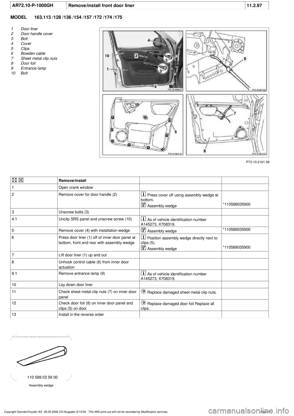
AR72.10-P-1000GH
Remove/install front door liner
11.2.97
MODEL
163.113 /128 /136 /154 /157 /172 /174 /175
P72.10-2161-06
1
Door liner
2
Door handle cover
3
Bolt
4
Cover
5
Clips
6
Bowden cable
7
Sheet metal clip nuts
8
Door foil
9
Entrance lamp
10
Bolt
Remove/install
1
Open crank window
2
Remove cover for door handle (2)
Press cover off using assembly wedge at
bottom.
Assembly wedge
*110589035900
3
Unscrew bolts (3)
4.1
Unclip SRS panel and unscrew screw (10)
As of vehicle identification number
A145273, X708319.
5
Remove cover (4) with installation wedge
Assembly wedge
*110589035900
6
Press door liner (1) off of inner door panel at
bottom, front and rear with assembly wedge
Position assembly wedge directly next to
clips (5).
Assembly wedge
*110589035900
7
Lift door liner (1) up and out
8
Unhook control cable (6) from inner door
actuation
9.1
Remove entrance lamp (9)
As of vehicle identification number
A145273, X708319.
10
Lay down door liner
11
Check sheet metal clip nuts (7) on inner door
panel
Replace damaged sheet metal clip nuts.
12
Check door foil (8) on inner door panel and
clips (5) on door
Replace damaged door foil Replace all
clips.
13
Install in the reverse order
Assembly wedge
110 589 03 59 00
Copyright DaimlerChrysler AG 09.05.2006 CD-Ausgabe G/10/04 . This WIS print-out will not be recorde
d by Modification services.
Page 1
Page 2124 of 4133

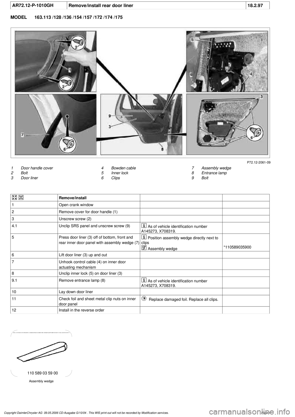
AR72.12-P-1010GH
Remove/install rear door liner
18.2.97
MODEL
163.113 /128 /136 /154 /157 /172 /174 /175
P72.12-2061-09
1
Door handle cover
2
Bolt
3
Door liner
7
Assembly wedge
8
Entrance lamp
9
Bolt
4
Bowden cable
5
Inner lock
6
Clips
Remove/install
1
Open crank window
2
Remove cover for door handle (1)
3
Unscrew screw (2)
4.1
Unclip SRS panel and unscrew screw (9)
As of vehicle identification number
A145273, X708319.
5
Press door liner (3) off of bottom, front and
rear inner door panel with assembly wedge (7)
Position assembly wedge directly next to
clips
Assembly wedge
*110589035900
6
Lift door liner (3) up and out
7
Unhook control cable (4) on inner door
actuating mechanism
8
Unclip inner lock (5) on door liner (3)
9.1
Remove entrance lamp (8)
As of vehicle identification number
A145273, X708319.
10
Lay down door liner
11
Check foil and sheet metal clip nuts on inner
door panel
Replace damaged foil. Replace all clips.
12
Install in the reverse order
Assembly wedge
110 589 03 59 00
Copyright DaimlerChrysler AG 09.05.2006 CD-Ausgabe G/10/04 . This WIS print-out will not be recorde
d by Modification services.
Page 1