1997 MERCEDES-BENZ ML350 check oil
[x] Cancel search: check oilPage 3191 of 4133

Valve seal not okay :
#
3
Remove/install/replace valve seal.
AR05.30-P-3500B
Cause 6:
Remedy 6:
00 001 70
1.5 mm hole missing on individual right
cylinder head covers at connection to
crankcase ventilation.
1
Check cylinder head cover
Up to production 06/1999.
Crankcase ventilation out of order, engine can
sludge up and consume oil as a result
Cylinder head cover not okay:
#
2
Remove/install/replace cylinder head
cover.
ENGINE
112
Air cleaner positioned on engine
side.
ENGINE
113
Air cleaner positioned on engine
side.
AR01.20-P-5014BV
ENGINE
112
Air cleaner positioned on engine side
ENGINE
113
Air cleaner positioned on engine side
AR01.20-P-5014B
Cause 7:
Remedy 7:
00 001 70
Engine oil sludging due to excessively long
engine oil change intervals
Service information: Oil sludge
SI18.00-P-0010A
If the service interval according to
ASSYST is exceeded, the engine oil sludges
up sooner or later depending on the oil
quality, type of operation and operating time.
Engine consumes oil.
See Service Information.
1
Print out ASSYST printout.
2
Check oil change intervals
3
Inform vehicle owner.
4
Remove/install/replace piston rings.
AR03.10-P-7311BV
Disassemble and clean sludged engines
completely because dirty oil usually gets into
clean-oil side due to clogged oil filter.
Cause 8:
Remedy 8:
00 001 70
Piston rings sticky or have coke deposits from
engine oils (e.g. API-S in USA) in connection
with regionally poor fuel quality.
Always use engine oils according to
Specifications for Operating Fluids 229.3, do
not add special additives to engine oil and fuel
BB00.40-P-0229-03A
1
Remove/install/replace piston rings.
AR03.10-P-7311BV
Cause 9:
Remedy 9:
00 001 70
Piston ring wear due to excessive
contamination/dust (model 163) through air
intake system.
1
Remove/install/replace gaskets on air
intake line and distribution element of
partial load ventilation.
e.g. due to incorrect assembly after
workshop visit or embrittlement of gaskets
The distribution element with optimized
material will be available as of 11/ 2000 as a
standard feature.
2
Remove/install/replace intake module.
Exterior oil loss, e.g. due to cast iron
porosity on left side of crankcase in area of
engine support is not considered to be oil
consumption
In the event of a customer complaint
regarding the engine oil consumption, always
determine the oil consumption definitely
because the oil indicator lamp can come on
due to other causes (e.g. defective oil sensor).
Commercially available tools
(see Workshop Equipment Manual)
Number
Designation
Make (e. g.)
Order number
WH58.30-Z-1009-05A
Flexible inspection light
Scope of supply 1 (complete unit):
-glass fiber optical fiber
-light projector
-230 V, storage case
-operating instructions
-graphics protocol
Richard Wolf GmbH
Pforzheimerstr. 32
D-75438 Knittlingen
Karl Storz GmbH
Mittelstr. 8
D-78532 Tuttlingen
1.00565.00
80902
WH58.30-Z-1010-05A
Flexible inspection light
Scope of delivery 2 (for workshops which already have an approved
Wolf or Storz inspection light):
-storage case
-operating instructions
-pictures protocol
Richard Wolf GmbH
Pforzheimerstr. 32
D-75438 Knittlingen
Karl Storz GmbH
Mittelstr. 8
D-78532 Tuttlingen
7.05065.00
K03506AJ
Copyright DaimlerChrysler AG 20.05.2006 CD-Ausgabe G/10/04 . This WIS print-out will not be recorde
d by Modification services.
Page 2
Page 3228 of 4133
A/C housing. Disconnect control module connector. To install reverse removal procedure. Recode 5-digit radio
security code. Using HHT, check for DTC and erase, and set clock.
A/C PUSH BUTTON CONTROL PANEL
Removal & Installation
1. Obtain 5-digit radio security code from vehicle owner. Disconnect negative battery cable. Using radio
removal plates, remove radio. Disconnect electrical connectors.
2. Remove instrument panel center section. Remove 4 A/C control panel screws and remove control panel.
Release pull cables and disconnect connectors. To install, reverse removal procedure. Recode radio. See
RECODING RADIO
under PROGRAMMING.
BLOWER MOTOR
Removal & Installation
Remove passenger-side instrument panel under cover. Remove blower motor mounting screws from A/C
housing unit. Disconnect blower motor connector and remove blower motor. To install, reverse removal
procedure.
COMPRESSOR
Removal & Installation
1. Discharge A/C system, using approved refrigerant recovery/recycling equipment. Remove accessory
drive belt. Disconnect low pressure refrigerant line from compressor. Discard "O" rings. Plug exposed
openings to protect A/C system from debris and moisture.
2. Disconnect high pressure refrigerant line from compressor. Discard "O" rings. Plug exposed openings to
protect A/C system from debris and moisture. Disconnect electrical connector. Remove compressor
mounting bolts.
3. Raise and support vehicle. Remove compressor from under vehicle without spilling refrigerant oil. To
install, reverse removal procedure. Ensure refrigerant oil quantity in compressor is correct. See
COMPRESSOR REFRIGERANT OIL CHECKING under GENERAL SERVICING. Tighten bolts to
specification. See TORQUE SPECIFICATIONS
.
CONDENSER
Removal & Installation
1. Discharge A/C system, using approved refrigerant recovery/recycling equipment. Remove cooling fans.
See COOLING FANS
. Disconnect refrigerant line from receiver-drier. See Fig. 5 . Discard "O" rings.
2. Plug exposed openings to protect A/C system from debris and moisture. Remove refrigerant line from
condenser. Remove radiator upper rubber seal. See Fig. 6
. Remove condenser upper mounting screws.
Lift condenser upward and remove. NOTE: Each time A/C compressor is removed and installed, receiver-drier must be
replaced.
2001 Mercedes-Benz ML320
2000-01 MANUAL A/C-HEATER SYSTEMS ML 320, ML 430 & ML 55
me
Saturday, October 02, 2010 3:25:10 PMPage 17 © 2006 Mitchell Repair Information Company, LLC.
Page 3248 of 4133
All models fitted with air conditioning
Do not carry repair operations out on the air conditioning circuit in the open air during moist weather.
Moisture in the refrigerant circuit reduces the system's refrigeration output and leads to damage to the
components. The acidic substances produced by moisture within the system decompose the desiccant in the
fluid reservoir and damage the entire system.
After separating/unscrewing refrigerant lines, immediately seal off the connection openings so that they are
airproof using suitable stop plugs (parts kit).
Replace the fluid reservoir every time you open up the refrigeration circuit.
Always store all spare components in a dry, sealed-off area. Do not remove stop plugs in new components until
just before they are installed. Use special care when handling the receiver/dryer with its integral desiccation
unit.
When a receiver/dryer is left open, the dryer unit quickly becomes saturated with moisture, rendering it useless.
Check drier cartridge packaging for damage. Dispose of drier cartridges with damaged packaging.
Install the desiccant cartridge no later than 20 minutes after opening the packaging.
Further protection against moisture is provided by carefully evacuating the air conditioning system following
repair operations. By generating vacuum in the system, the evacuation process removes any moisture that might
have penetrated into the system.
NOTES ON RETROFITTING AN AIR CONDITIONING SYSTEM - AH83.30-P-0001-02A
Do not remove the plugs on any of the components until immediately prior to installation.
Fit all AC lines with new sealing rings. Coat thread and sealing rings with compressor oil.
BASIC KNOWLEDGE
VENTILATION, FUNCTION - GF83.10-P-2000GH
MODEL 163 up to 31.8.01
2001 Mercedes-Benz ML320
1998-2005 HVAC Climate Control - 163 Chassis
me
Saturday, October 02, 2010 3:23:14 PMPage 4 © 2006 Mitchell Repair Information Company, LLC.
Page 3432 of 4133
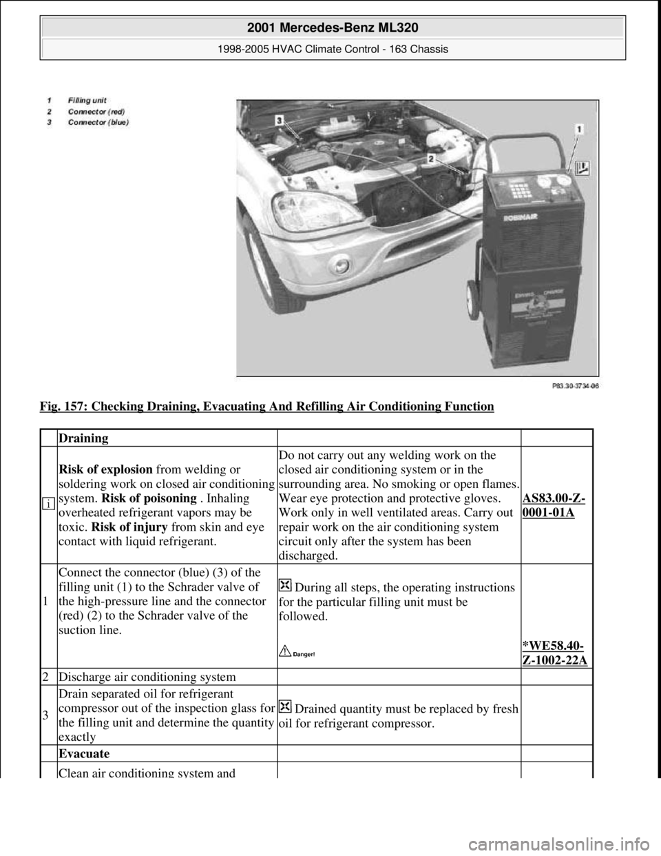
Fig. 157: Checking Draining, Evacuating And Refilling Air Conditioning Function
Draining
Risk of explosion from welding or
soldering work on closed air conditioning
system. Risk of poisoning . Inhaling
overheated refrigerant vapors may be
toxic. Risk of injury from skin and eye
contact with liquid refrigerant.
Do not carry out any welding work on the
closed air conditioning system or in the
surrounding area. No smoking or open flames.
Wear eye protection and protective gloves.
Work only in well ventilated areas. Carry out
repair work on the air conditioning system
circuit only after the system has been
discharged.
AS83.00-Z-
0001-01A
1
Connect the connector (blue) (3) of the
filling unit (1) to the Schrader valve of
the high-pressure line and the connector
(red) (2) to the Schrader valve of the
suction line.
During all steps, the operating instructions
for the particular filling unit must be
followed.
*WE58.40-
Z-1002-22A
2Discharge air conditioning system
3
Drain separated oil for refrigerant
compressor out of the inspection glass for
the filling unit and determine the quantity
exactly
Drained quantity must be replaced by fresh
oil for refrigerant compressor.
Evacuate
Clean air conditioning system and
2001 Mercedes-Benz ML320
1998-2005 HVAC Climate Control - 163 Chassis
me
Saturday, October 02, 2010 3:23:18 PMPage 188 © 2006 Mitchell Repair Information Company, LLC.
Page 3433 of 4133
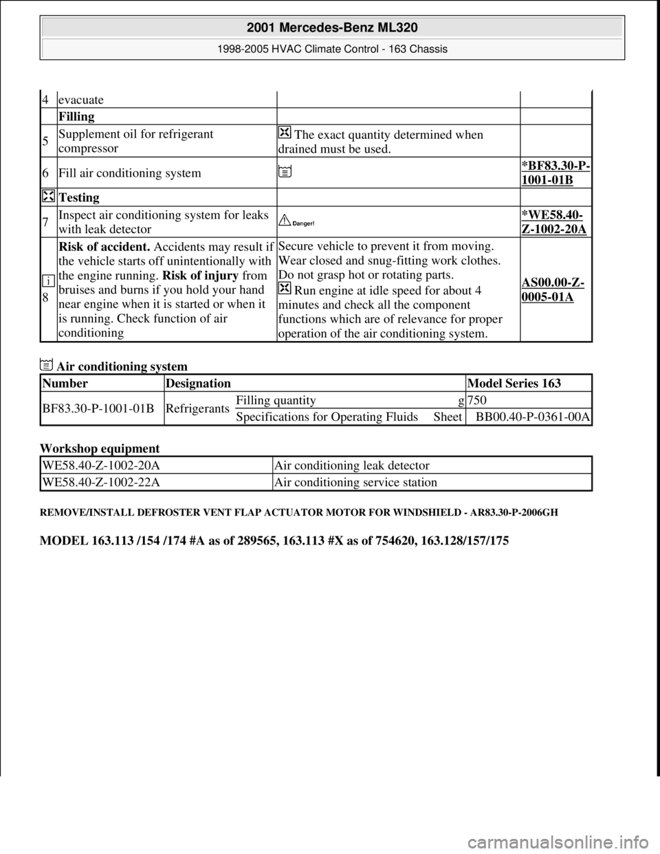
Air conditioning system
Workshop equipment
REMOVE/INSTALL DEFROSTER VENT FLAP ACTUATOR MOTOR FOR WINDSHIELD - AR83.30-P-2006GH
MODEL 163.113 /154 /174 #A as of 289565, 163.113 #X as of 754620, 163.128/157/175
4evacuate
Filling
5Supplement oil for refrigerant
compressor The exact quantity determined when
drained must be used.
6Fill air conditioning system *BF83.30-P-
1001-01B
Testing
7Inspect air conditioning system for leaks
with leak detector *WE58.40-
Z-1002-20A
8
Risk of accident. Accidents may result if
the vehicle starts off unintentionally with
the engine running. Risk of injury from
bruises and burns if you hold your hand
near engine when it is started or when it
is running. Check function of air
conditioningSecure vehicle to prevent it from moving.
Wear closed and snug-fitting work clothes.
Do not grasp hot or rotating parts.
Run engine at idle speed for about 4
minutes and check all the component
functions which are of relevance for proper
operation of the air conditioning system.
AS00.00-Z-
0005-01A
NumberDesignationModel Series 163
BF83.30-P-1001-01BRefrigerantsFilling quantityg750
Specifications for Operating FluidsSheetBB00.40-P-0361-00A
WE58.40-Z-1002-20AAir conditioning leak detector
WE58.40-Z-1002-22AAir conditioning service station
2001 Mercedes-Benz ML320
1998-2005 HVAC Climate Control - 163 Chassis
me
Saturday, October 02, 2010 3:23:18 PMPage 189 © 2006 Mitchell Repair Information Company, LLC.
Page 3441 of 4133
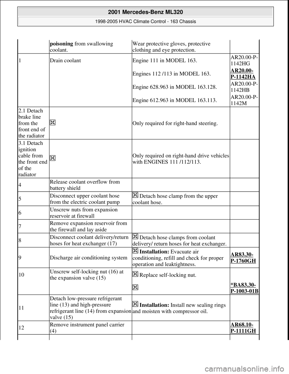
poisoning from swallowing
coolant.Wear protective gloves, protective
clothing and eye protection.
1Drain coolantEngine 111 in MODEL 163.AR20.00-P-
1142HG
Engines 112 /113 in MODEL 163.AR20.00-
P-1142HA
Engine 628.963 in MODEL 163.128.AR20.00-P-
1142HB
Engine 612.963 in MODEL 163.113.AR20.00-P-
1142M
2.1 Detach
brake line
from the
front end of
the radiator
Only required for right-hand steering.
3.1 Detach
ignition
cable from
the front end
of the
radiator
Only required on right-hand drive vehicles
with ENGINES 111 /112/113.
4Release coolant overflow from
battery shield
5Disconnect upper coolant hose
from the electric coolant pump Detach hose clamp from the upper
coolant hose.
6Unscrew nuts from expansion
reservoir at firewall
7Remove expansion reservoir from
the firewall and lay aside
8Disconnect coolant delivery/return
hoses for heat exchanger (17) Detach hose clamps from coolant
delivery/ return hoses for heat exchanger.
9Discharge air conditioning system
Installation: Evacuate air
conditioning, refill and check for proper
operation and leaktightness.AR83.30-
P-1760GH
10Unscrew self-locking nut (16) at
the expansion valve (15) Replace self-locking nut.
*BA83.30-
P-1003-01B
11
Detach low-pressure refrigerant
line (13) and high-pressure
refrigerant line (14) from expansion
valve (15)
Installation: Install new sealing rings
and moisten with compressor oil.
12Remove instrument panel carrier
(4) AR68.10-
P-1111GH
2001 Mercedes-Benz ML320
1998-2005 HVAC Climate Control - 163 Chassis
me
Saturday, October 02, 2010 3:23:18 PMPage 197 © 2006 Mitchell Repair Information Company, LLC.
Page 3446 of 4133
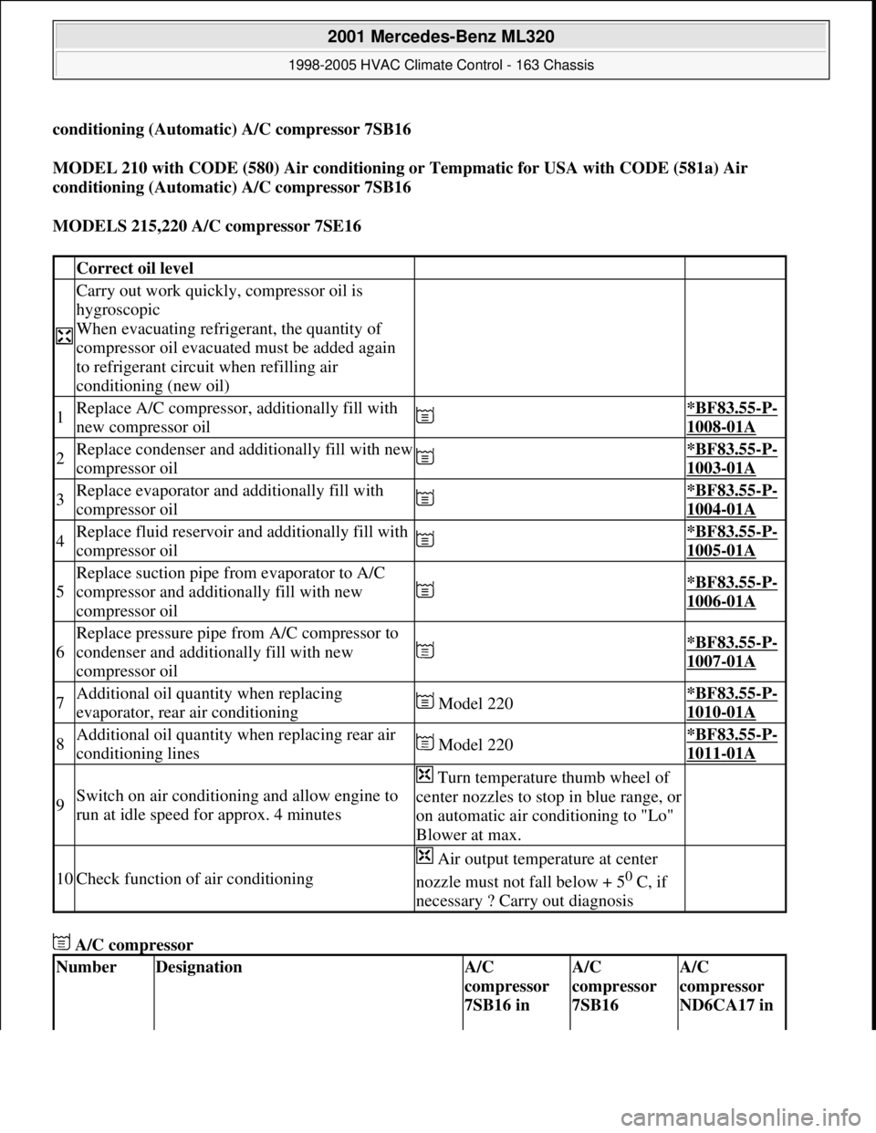
conditioning (Automatic) A/C compressor 7SB16
MODEL 210 with CODE (580) Air conditioning or Tempmatic for USA with CODE (581a) Air
conditioning (Automatic) A/C compressor 7SB16
MODELS 215,220 A/C compressor 7SE16
A/C compressor
Correct oil level
Carry out work quickly, compressor oil is
hygroscopic
When evacuating refrigerant, the quantity of
compressor oil evacuated must be added again
to refrigerant circuit when refilling air
conditioning (new oil)
1Replace A/C compressor, additionally fill with
new compressor oil *BF83.55-P-
1008-01A
2Replace condenser and additionally fill with new
compressor oil *BF83.55-P-
1003-01A
3Replace evaporator and additionally fill with
compressor oil *BF83.55-P-
1004-01A
4Replace fluid reservoir and additionally fill with
compressor oil *BF83.55-P-
1005-01A
5
Replace suction pipe from evaporator to A/C
compressor and additionally fill with new
compressor oil
*BF83.55-P-
1006-01A
6
Replace pressure pipe from A/C compressor to
condenser and additionally fill with new
compressor oil
*BF83.55-P-
1007-01A
7Additional oil quantity when replacing
evaporator, rear air conditioning Model 220*BF83.55-P-
1010-01A
8Additional oil quantity when replacing rear air
conditioning lines Model 220*BF83.55-P-
1011-01A
9Switch on air conditioning and allow engine to
run at idle speed for approx. 4 minutes
Turn temperature thumb wheel of
center nozzles to stop in blue range, or
on automatic air conditioning to "Lo"
Blower at max.
10Check function of air conditioning
Air output temperature at center
nozzle must not fall below + 5
0 C, if
necessary ? Carry out diagnosis
NumberDesignationA/C
compressor
7SB16 in A/C
compressor
7SB16 A/C
compressor
ND6CA17 in
2001 Mercedes-Benz ML320
1998-2005 HVAC Climate Control - 163 Chassis
me
Saturday, October 02, 2010 3:23:18 PMPage 202 © 2006 Mitchell Repair Information Company, LLC.
Page 3457 of 4133
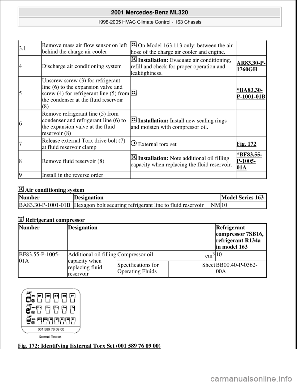
Air conditioning system
Refrigerant compressor
Fig. 172: Identifying External Torx Set (001 589 76 09 00)
3.1Remove mass air flow sensor on left
behind the charge air cooler On Model 163.113 only: between the air
hose of the charge air cooler and engine.
4Discharge air conditioning system
Installation: Evacuate air conditioning,
refill and check for proper operation and
leaktightness.AR83.30-P-
1760GH
5
Unscrew screw (3) for refrigerant
line (6) to the expansion valve and
screw (4) for refrigerant line (5) from
the condenser at the fluid reservoir
(8)
*BA83.30-
P-1001-01B
6
Remove refrigerant line (5) from
condenser and refrigerant line (6) to
the expansion valve at the fluid
reservoir (8)
Installation: Install new sealing rings
and moisten with compressor oil.
7Release external Torx drive bolt (7)
at fluid reservoir clamp External torx setFig. 172
8Remove fluid reservoir (8) Installation: Note additional oil filling
capacity when replacing the fluid reservoir.*BF83.55-
P-1005-
01A
9Install in the reverse order
NumberDesignationModel Series 163
BA83.30-P-1001-01BHexagon bolt securing refrigerant line to fluid reservoirNM10
NumberDesignationRefrigerant
compressor 7SB16,
refrigerant R134a
in model 163
BF83.55-P-1005-
01AAdditional oil filling
capacity when
replacing fluid
reservoirCompressor oilcm3 10
Specifications for
Operating FluidsSheetBB00.40-P-0362-
00A
2001 Mercedes-Benz ML320
1998-2005 HVAC Climate Control - 163 Chassis
me
Saturday, October 02, 2010 3:23:18 PMPage 213 © 2006 Mitchell Repair Information Company, LLC.