Page 1205 of 4133
If the parking lock is engaged, the ignition key has been removed and the service brake is not activated, the
locking pawl (39) blocks the detent plate (38). See Fig. 19
. The park pawl cannot be released. The park pawl
can only be released by turning the ignition key to position "1" and pressing the brake pedal. Starting from
ignition key position "1" the locking cam (61) in the steering lock releases the control cable (53). When the
brake pedal is depressed, the lock lever (55) and roller (58) are twisted down, the return spring at the brake
pedal (57) is tensionsed and the release lever (56) is released.
The force of the pressure spring (64) is now applied via the cables (53, 54) against the lesser force of the
pressure spring (62) and pulls the locking valve (60) in front of the contour of the locking cam (61). The locking
pawl (39) is simultaneously turned via the link rod and lifts up off the detent plate (38).
The parking lock can now be released.
The design of the parking lock interlock is the same as for the steering lock interlock and it functions with
reciprocal action to the steering lock interlock.
Steering Lock Interlock, Function
2001 Mercedes-Benz ML320
1998-03 AUTOMATIC TRANSMISSIONS Complete Transmissions - ML 320 - 722.662
me
Saturday, October 02, 2010 3:15:26 PMPage 36 © 2006 Mitchell Repair Information Company, LLC.
Page 1206 of 4133
Fig. 20: Steering Lock Interlock, Function
Courtesy of MERCEDES-BENZ OF NORTH AMERICA.
2001 Mercedes-Benz ML320
1998-03 AUTOMATIC TRANSMI SSIONS Complete Transmissions - ML 320 - 722.662
me
Saturday, October 02, 2010 3:15:26 PMPage 37 © 2006 Mitchell Repair Information Company, LLC.
Page 1207 of 4133
Operation
The steering lock interlock prevents the ignition key being removed when the parking lock is not engaged.
The locking pawl (39) is positioned on the exterior contour of the detent plate (38) if the parking lock is not
engaged and if the brake pedal is not depressed. See Fig. 20
.
The cables (53, 54) hold the locking valve (60) in its position in front of the locking cam (61) against the force
of the pressure spring. Therefore, the ignition key cannot be turned to the "0" position.
In selector lever position "P" and with the brake pedal in the rest position, the force of the return spring (57) can
pull the locking pawl (39) under the stop at the detent plate (38) and the pressure spring (62) simultaneously
pulls the locking valve (60) away from the locking cam (61).
The ignition key can now be turned to the "0" position and removed from the ignition.
The design of the parking lock interlock is the same as for the steering lock interlock and it functions with
reciprocal action to the steering lock interlock.
Parking Lock, Location/Task/Design/Function
See PARKING LOCK, LOCATION/TASK/DESIGN/FUNCTION
.
Parking Lock, Location/Task/Design/Function
2001 Mercedes-Benz ML320
1998-03 AUTOMATIC TRANSMISSIONS Complete Transmissions - ML 320 - 722.662
me
Saturday, October 02, 2010 3:15:26 PMPage 38 © 2006 Mitchell Repair Information Company, LLC.
Page 1330 of 4133
ETC Control Unit, Location/Task
Fig. 94: ETC Control Unit, Location/Task
Courtesy of MERCEDES-BENZ OF NORTH AMERICA.
ETC Control Unit, Location
See ETC CONTROL UNIT, LOCATION
.
ETC Control Unit, Task
See ETC CONTROL UNIT, TASK (EXCEPT CODE (428A) STEERING WHEEL SWITCH
BUTTONS).
ETC Control Unit, Location
2001 Mercedes-Benz ML320
1998-03 AUTOMATIC TRANSMISSIONS Complete Transmissions - ML 320 - 722.662
me
Saturday, October 02, 2010 3:15:27 PMPage 161 © 2006 Mitchell Repair Information Company, LLC.
Page 1501 of 4133
The Audio 30 APS does not have a number pad. For this reason, it is not possible to control the telephone over
the radio (see operating instructions).
On vehicles (as of approx. 07.99) with multifunction steering wheel (telephone control with keys on steering
wheel) this function is then also possible with the Audio 30 APS navigation system.
NOTES ON TRAFFIC PRO NAVIGATION SYSTEM - AH82.61-P-0002-01A
Models 129, 140, 163, 168, 170, 202, 208, 210
Customer information, installation position for GPS antenna
There are two different installation locations for the GSP antenna:
1. Standard GPS antenna from DaimlerChrysler on roof or trunk lid. This version offers the best reception
and is therefore preferable.
2. Use of magnetic antenna in vehicle passenger compartment. This version is part of the kit from the
Becker company and installation is described in Becker installation instructions.
Notes on installation of Becker GPS antenna
The GPS antenna can only be installed horizontally with a maximum deviation of 10° from horizontal.
The GPS antenna should always have an unobstructed view of the sky. Tinted windows can reduce the function
of the GPS antenna considerably.
When installing the GPS antenna always ensure that the arched surface of the antenna points upwards.
NOTES ON FIBER OPTIC CABLE - AH82.70-P-0001-02A
Model 129, 163, 168, 170, 202, 203, 208, 209, 210, 215, 220, 230, 414,
463.243/244/245/246/247/248/249/250/254/270/271/303/309/322/323/332/333/340/341
Illustrated on Model 202 sedan
2001 Mercedes-Benz ML320
1998-2005 ACCESSORIES & BODY, CAB Electrical System - Body - 163 Chassis
me
Saturday, October 02, 2010 3:30:04 PMPage 6 © 2006 Mitchell Repair Information Company, LLC.
Page 1503 of 4133
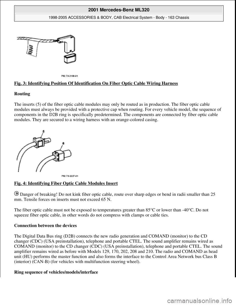
Fig. 3: Identifying Position Of Identification On Fiber Optic Cable Wiring Harness
Routing
The inserts (5) of the fiber optic cable modules may only be routed as in production. The fiber optic cable
modules must always be pr ovided with a protective cap when routing. For every vehicle model, the sequence of
components in the D2B ring is specifically predetermi ned. The components are connected by fiber optic cable
modules. They are secured to a wiring ha rness with an orange-colored casing.
Fig. 4: Identifying Fiber Optic Cable Modules Insert
Danger of breaking! Do not kink fiber optic cable, route over sharp edges or be nd in radii smaller than 25
mm. Tensile forces on inserts must not exceed 65 N.
The fiber optic cable must not be exposed to temperat ures greater than 85°C or lower than -40°C. Do not
squeeze fiber optic cable, in other words do not compress with clamps or cable ties.
Connection between the devices
The Digital Data Bus ring (D2B) connects the new ra dio generation and COMAND (monitor) to the CD
changer (CDC) (USA preinstallati on), telephone and portable CTEL. The sound amplifier remains wired as
COMAND (monitor) to the CD changer (CDC) (USA preinstallation), telephone and portable CTEL. The sound
amplifier remains wired as befo re with Models 129, 170, 202, 208 and 210. The radio and COMAND as head
unit (HU) performs the master function and also forms the interface to the Control Area Network bus Class B
(interior) (CAN-B) (for vehicles wi th multifunction steering wheel).
Ring sequence of vehi cles/models/interface
2001 Mercedes-Benz ML320
1998-2005 ACCESSORIES & BODY, CAB Electr ical System - Body - 163 Chassis
me
Saturday, October 02, 2010 3:30:04 PMPage 8 © 2006 Mitchell Repair Information Company, LLC.
Page 1534 of 4133
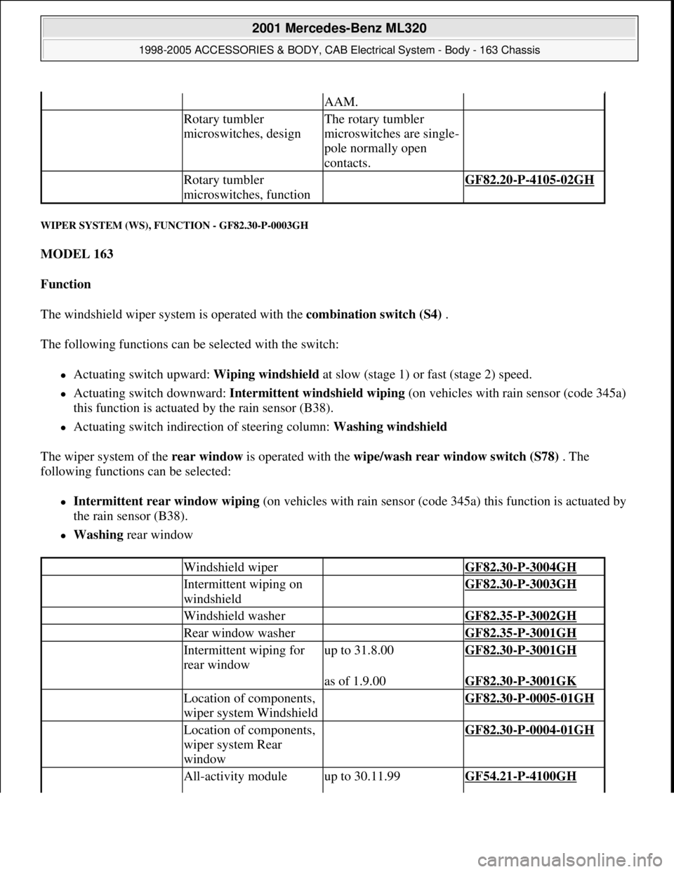
WIPER SYSTEM (WS), FUNCTION - GF82.30-P-0003GH
MODEL 163
Function
The windshield wiper system is operated with the combination switch (S4) .
The following functions can be selected with the switch:
Actuating switch upward: Wiping windshield at slow (stage 1) or fast (stage 2) speed.
Actuating switch downward: Intermittent windshield wiping (on vehicles with rain sensor (code 345a)
this function is actuated by the rain sensor (B38).
Actuating switch indirection of steering column: Washing windshield
The wiper system of the rear window is operated with the wipe/wash rear window switch (S78) . The
following functions can be selected:
Intermittent rear window wiping (on vehicles with rain sensor (code 345a) this function is actuated by
the rain sensor (B38).
Washing rear window
AAM.
Rotary tumbler
microswitches, designThe rotary tumbler
microswitches are single-
pole normally open
contacts.
Rotary tumbler
microswitches, function GF82.20-P-4105-02GH
Windshield wiper GF82.30-P-3004GH
Intermittent wiping on
windshield GF82.30-P-3003GH
Windshield washer GF82.35-P-3002GH
Rear window washer GF82.35-P-3001GH
Intermittent wiping for
rear windowup to 31.8.00GF82.30-P-3001GH
as of 1.9.00GF82.30-P-3001GK
Location of components,
wiper system Windshield GF82.30-P-0005-01GH
Location of components,
wiper system Rear
window GF82.30-P-0004-01GH
All-activity moduleup to 30.11.99GF54.21-P-4100GH
2001 Mercedes-Benz ML320
1998-2005 ACCESSORIES & BODY, CAB Electrical System - Body - 163 Chassis
me
Saturday, October 02, 2010 3:30:04 PMPage 39 © 2006 Mitchell Repair Information Company, LLC.
Page 1549 of 4133
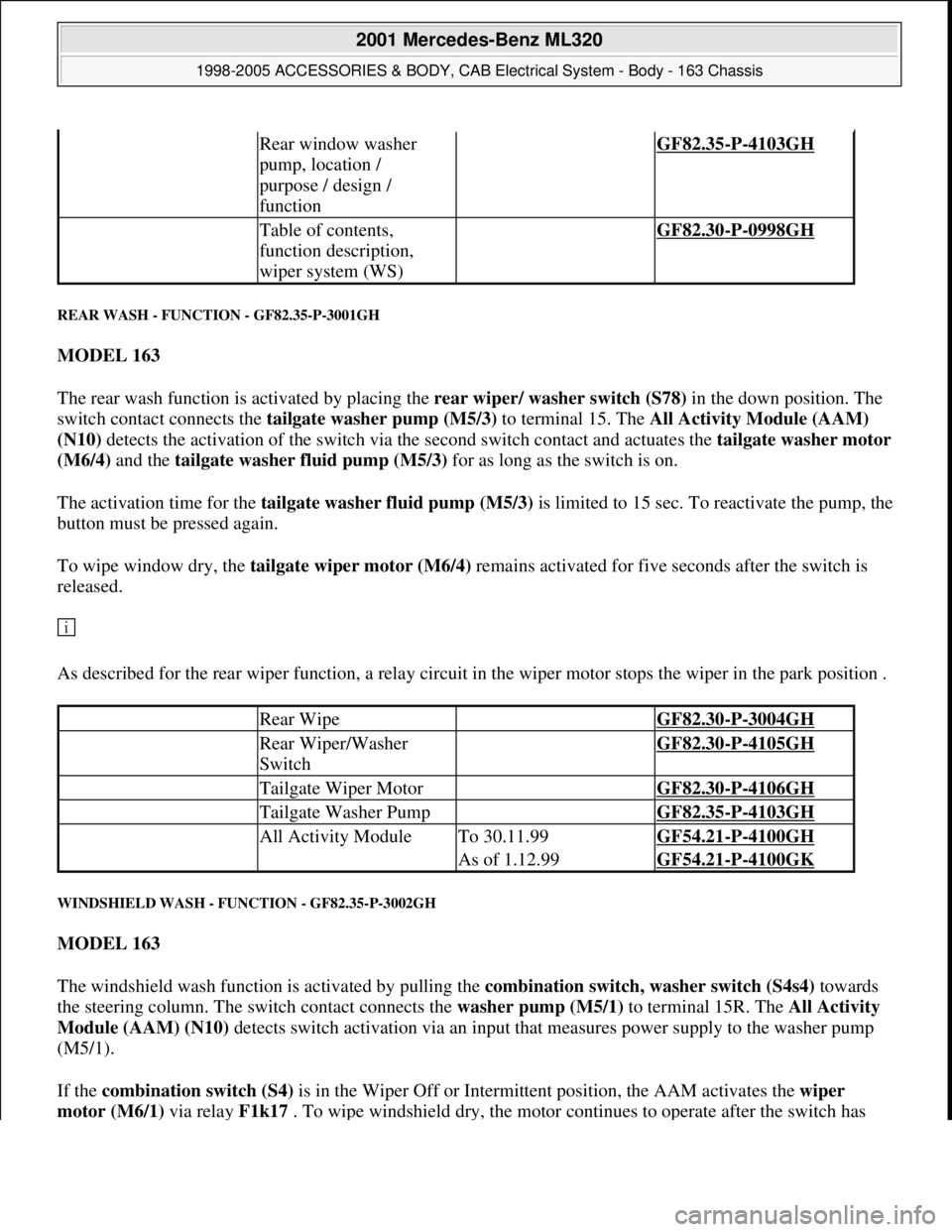
REAR WASH - FUNCTION - GF82.35-P-3001GH
MODEL 163
The rear wash function is activated by placing the rear wiper/ washer switch (S78) in the down position. The
switch contact connects the tailgate washer pump (M5/3) to terminal 15. The All Activity Module (AAM)
(N10) detects the activation of the switch via the second switch contact and actuates the tailgate washer motor
(M6/4) and the tailgate washer fluid pump (M5/3) for as long as the switch is on.
The activation time for the tailgate washer fluid pump (M5/3)is limited to 15 sec. To reactivate the pump, the
button must be pressed again.
To wipe window dry, the tailgate wiper motor (M6/4) remains activated for five seconds after the switch is
released.
As described for the rear wiper function, a relay circuit in the wiper motor stops the wiper in the park position .
WINDSHIELD WASH - FUNCTION - GF82.35-P-3002GH
MODEL 163
The windshield wash function is activated by pulling the combination switch, washer switch (S4s4) towards
the steering column. The switch contact connects the washer pump (M5/1) to terminal 15R. The All Activity
Module (AAM) (N10) detects switch activation via an input that measures power supply to the washer pump
(M5/1).
If the combination switch (S4) is in the Wiper Off or Intermittent position, the AAM activates the wiper
motor (M6/1) via rela
y F1k17 . To wipe windshield dry, the motor continues to operate after the switch has
Rear window washer
pump, location /
purpose / design /
function GF82.35-P-4103GH
Table of contents,
function description,
wiper system (WS) GF82.30-P-0998GH
Rear Wipe GF82.30-P-3004GH
Rear Wiper/Washer
Switch GF82.30-P-4105GH
Tailgate Wiper Motor GF82.30-P-4106GH
Tailgate Washer Pump GF82.35-P-4103GH
All Activity ModuleTo 30.11.99GF54.21-P-4100GH
As of 1.12.99GF54.21-P-4100GK
2001 Mercedes-Benz ML320
1998-2005 ACCESSORIES & BODY, CAB Electrical System - Body - 163 Chassis
me
Saturday, October 02, 2010 3:30:05 PMPage 54 © 2006 Mitchell Repair Information Company, LLC.