1997 MERCEDES-BENZ ML320 steering
[x] Cancel search: steeringPage 1569 of 4133
4-channel power amplifier for vehicle loudspeakers
System interlinkage
The radio and navigation unit (A2/56) is provided with the following components for data exchange with
external digital components:
CAN (A1 -A2/56)
The radio and navigation unit (A2/56) is connected with the instrument cluster (A1) via a separate
CAN bus. The difference to the other CAN systems is indicated by the spelling CAN bus (A1-A2/56).
The CAN bus (A1-A2/56) allows the following functions:
Operation of the radio and navigation unit (A2/56)is also possible with the multifunction steering
wheel.
The multifunction display (A1/p13) in the instrument cluster (A1) can display navigation
information on the current operating status of the radio and navigation unit (A2/56) .
The connection to the CAN bus (A1-A2/56) is only realized on models 208 and 210. (Status 3/99)
Digital data bus (D2B)
Data can be exchanged between the external audio components, the telephone system and - if present -
the voice control system over the D2B bus. This allows control data as well as the actual audio signals
(e.g. music from CD changer) to be transferred.
The only additional D2B component presently possible is the CD changer (A2/6) (Status: 3/99)
K bus (diagnostic interface)
Data exchange is accomplished between the diagnostic interface and the hand-held tester (reading out
DTCs and actual values, ...).
The communication between the HHT and all other D2B components is accomplished over the radio
and navigation unit (A2/56) diagnostic interface.
Audio 30 APS, location of
componentsModel 163GF82.61-P-0002-01D
Model 168GF82.61-P-0002-01B
Model 170GF82.61-P-0002-01A
Model 208, model 210&.2.(GF82.61-P-0002-
01C)
Audio 30 APS block
diagramModel 163GF82.61-P-0002-02D
Model 168GF82.61-P-0002-02B
2001 Mercedes-Benz ML320
1998-2005 ACCESSORIES & BODY, CAB Electrical System - Body - 163 Chassis
me
Saturday, October 02, 2010 3:30:05 PMPage 74 © 2006 Mitchell Repair Information Company, LLC.
Page 1662 of 4133
MODEL 163.113/136/154/172 With 5 L reservoir
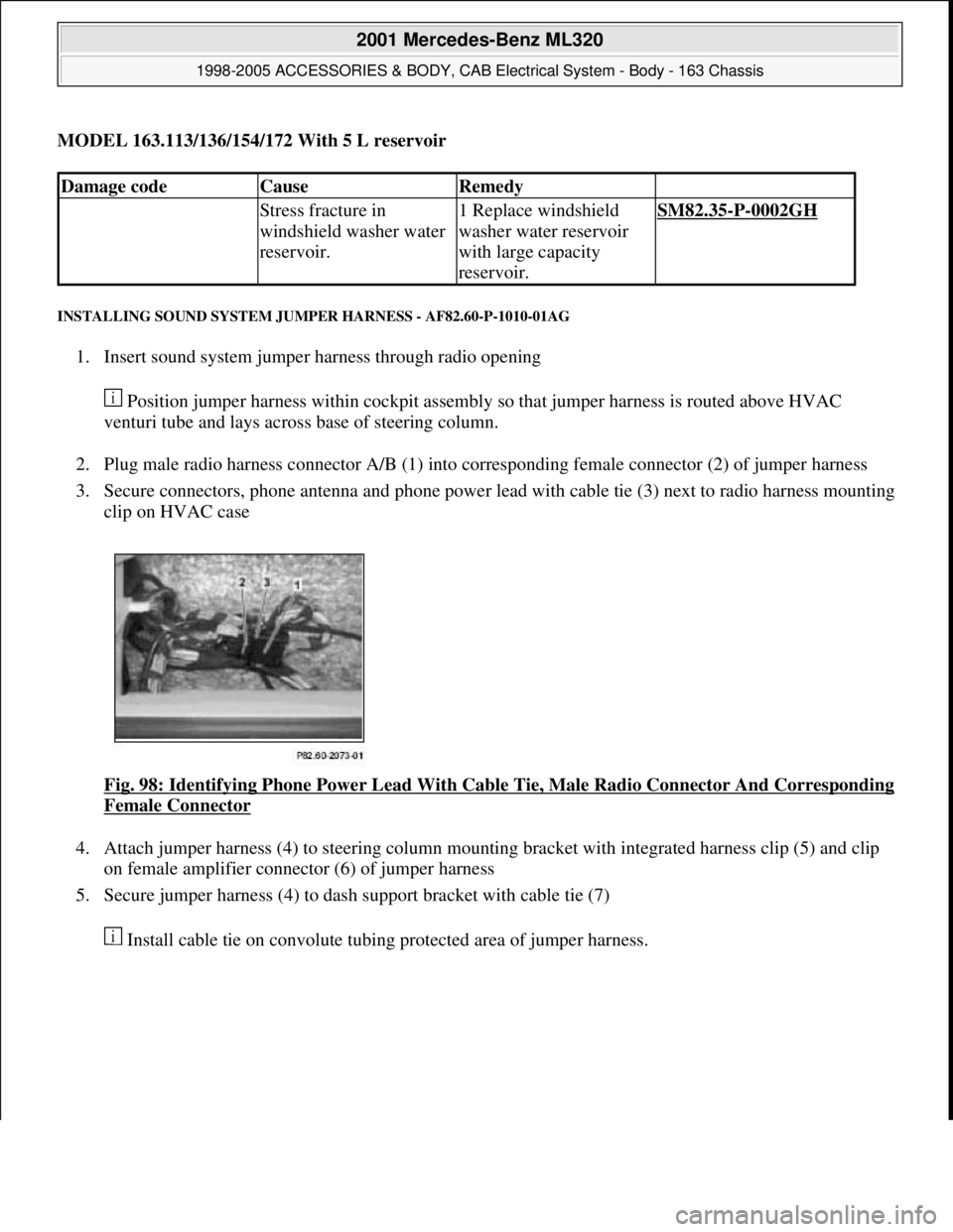
INSTALLING SOUND SYSTEM JUMPER HARNESS - AF82.60-P-1010-01AG
1. Insert sound system jumper harness through radio opening
Position jumper harness within cockpit assembly so that jumper harness is routed above HVAC
venturi tube and lays across base of steering column.
2. Plug male radio harness connector A/B (1) into corresponding female connector (2) of jumper harness
3. Secure connectors, phone antenna and phone power lead with cable tie (3) next to radio harness mounting
clip on HVAC case
Fi
g. 98: Identifying Phone Power Lead With Cable Tie, Male Radio Connector And Corresponding
Female Connector
4. Attach jumper harness (4) to steering column mounting bracket with integrated harness clip (5) and clip
on female amplifier connector (6) of jumper harness
5. Secure jumper harness (4) to dash support bracket with cable tie (7)
Install cable tie on convolute tubin
g protected area of jumper harness.
Damage codeCauseRemedy
Stress fracture in
windshield washer water
reservoir.1 Replace windshield
washer water reservoir
with large capacity
reservoir.SM82.35-P-0002GH
2001 Mercedes-Benz ML320
1998-2005 ACCESSORIES & BODY, CAB Electrical System - Body - 163 Chassis
me
Saturday, October 02, 2010 3:30:06 PMPage 167 © 2006 Mitchell Repair Information Company, LLC.
Page 1664 of 4133
![MERCEDES-BENZ ML320 1997 Complete Repair Manual MODEL 163 with CODE (259) Radio Premium with Bose sound system
Parts ordering notes
PROGRAM CHANGE ALTHOUGH RDS [RADIO DATA SYSTEM] AND REGIONALIZATION ARE SWITCHED ON -
AF82.60-P-1062A
MODEL 129, MERCEDES-BENZ ML320 1997 Complete Repair Manual MODEL 163 with CODE (259) Radio Premium with Bose sound system
Parts ordering notes
PROGRAM CHANGE ALTHOUGH RDS [RADIO DATA SYSTEM] AND REGIONALIZATION ARE SWITCHED ON -
AF82.60-P-1062A
MODEL 129,](/manual-img/4/57305/w960_57305-1663.png)
MODEL 163 with CODE (259) Radio Premium with Bose sound system
Parts ordering notes
PROGRAM CHANGE ALTHOUGH RDS [RADIO DATA SYSTEM] AND REGIONALIZATION ARE SWITCHED ON -
AF82.60-P-1062A
MODEL 129, 140, 163, 168, 170, 171, 202, 203, 208, 209, 210, 211, 215, 220, 230, 463 with RDS radio
Damage codeCauseRemedy
Speaker wires picking up
interference noise from
surrounding wiring1 Remove radioAR82.60-P-7502EA
2 Remove upper center
console storage
compartment
3 Remove lower dash
panel below steering
columnAR68.10-P-1500GH
4 Install sound system
jumper harness
AF82.60-P-1010-01AG
5 Reinstall in opposite
order
Part no.DesignationQuantity
163 540 98 05Jumper harness for Bose sound
system1
Damage codeCauseRemedy
Station change without
obvious cause.
Some radio stations
which had originally
transmitted regional
identification have been
transmitting the RDS
signals without regional
identification for some
time.
Without regional
identification it is no
longer possible to
separate stations with the
same station name which
transmit different
programs.1 Point out the facts to
the customer.
Do not replace any
devices, state of the art
engineering.
2001 Mercedes-Benz ML320
1998-2005 ACCESSORIES & BODY, CAB Electrical System - Body - 163 Chassis
me
Saturday, October 02, 2010 3:30:06 PMPage 169 © 2006 Mitchell Repair Information Company, LLC.
Page 1671 of 4133
LOSS OF SOUND IN COMAND SYSTEM AND/OR TELEPHONE NOT FUNCTIONING - AF82.70-P-1090A
MODEL 163, 203, 208, 209, 210, 215, 220, 230, 463 with CODE (853) MB standard cellular telephone
Nokia 6091
Parts ordering notes
PORTABLE CTEL CANNOT BE OPERATED OVER STEERING WHEEL OR COMAND/RADIO - AF82.70-P-6090A
Network is overloaded
The telephone
system has been
checked technically Do not remove/install/replace
any parts. It is not necessary to
replace the telephone control
module due to call interruptions.
1 Ask network provider about
traffic at point in question.
If the customer uses a twin
card it is necessary to switch off
the additionally (externally)
operated cellular telephone
before the vehicle's telephone
system is switched on.
Damage codeCauseRemedy
Fixed installation telephone
control unit.1 Read out series number.
Cyclical loss of sound in
COMAND system for 2 - 3
seconds (Nokia 6091).
Telephone temporarily not
functioning. via the receiver using the
key combination: *#06#
The series number can also be
found on the sticker on the
control unit.
Concerns fixed
installation control unit part
no. A 203 820 70 26. When
reading out with STAR
DIAGNOSIS (quick test)
part no. 000 000 00 00
appears with these control
units.If the affected series number
is installed: ?
Affected Nokia series
numbers:
from 350109/20/038841/6
up to 350109/20/047721/92 Remove/install/replace fixed
installation telephone control
unit.
Part no.DesignationQuantity
A 203 820 70 26Fixed installation telephone
control unitAs required
2001 Mercedes-Benz ML320
1998-2005 ACCESSORIES & BODY, CAB Electrical System - Body - 163 Chassis
me
Saturday, October 02, 2010 3:30:07 PMPage 176 © 2006 Mitchell Repair Information Company, LLC.
Page 1802 of 4133
possible from the
connector on the radio
3Remove cover on right
under the instrument
panel Left hand steering vehicle up
to 31.8.99.AR68.10-P-1520GH
Left hand steering vehicle as
of 1.9.99.AR68.10-P-1520GI
Right-hand drive vehicle.AR68.10-P-1500GH
4Remove right-hand
side entrance strip AR68.30-P-4100GH
5Remove footwell cover
on right AR68.30-P-4010GH
6Unscrew the bolt for
the outer rear seat belt
on the right side
7Remove the front load
compartment hooks on
the right C-pillar
8Remove load
compartment cover and
unscrew the bolt in the
bracket
9Remove cover for the
CD changer and
unscrew bolt behind
the cover in the top left
corner
10Disconnect D2B plug
from CD changer and
unclip the wiring
harness from the
bracket
11Remove the existing
D2B wiring harness
between the CD
changer and firewall at
the transmission tunnel Cut off the existing D2B
wiring harness at the last tie
strap between the heater housing
and firewall.
Only if the D2B wiring
harness is NOT in the interior
wiring harness .
Install
12Plug the plug of the
new D2B wiring
harness into the CD
changer and route the
wiring harness along Risk of breakage! Do not
kink or stretch fiber optic cable
Before routing, push the caps
onto the fiber optical cable.
Fasten the wiring harness to AR82.95-P-0005-01A
2001 Mercedes-Benz ML320
1998-2005 ACCESSORIES & BODY, CAB Electrical System - Body - 163 Chassis
me
Saturday, October 02, 2010 3:30:10 PMPage 307 © 2006 Mitchell Repair Information Company, LLC.
Page 1804 of 4133
Seat belts/emergency tensioning retractors
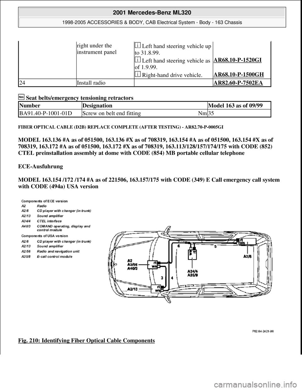
FIBER OPTICAL CABLE (D2B) REPLACE COMPLETE (AFTER TESTING) - AR82.70-P-0005GI
MODEL 163.136 #A as of 051500, 163.136 #X as of 708319, 163.154 #A as of 051500, 163.154 #X as of
708319, 163.172 #A as of 051500, 163.172 #X as of 708319, 163.113/128/157/174/175 with CODE (852)
CTEL preinstallation assembly at dome with CODE (854) MB portable cellular telephone
ECE-Ausfuhrung
MODEL 163.154 /172 /174 #A as of 221506, 163.157/175 with CODE (349) E Call emergency call system
with CODE (494a) USA version
Fig. 210: Identifying Fiber Optical Cable Components
right under the
instrument panel Left hand steering vehicle up
to 31.8.99.
Left hand steering vehicle as
of 1.9.99.AR68.10-P-1520GI
Right-hand drive vehicle.AR68.10-P-1500GH
24Install radio AR82.60-P-7502EA
NumberDesignationModel 163 as of 09/99
BA91.40-P-1001-01DScrew on belt end fittingNm35
2001 Mercedes-Benz ML320
1998-2005 ACCESSORIES & BODY, CAB Electrical System - Body - 163 Chassis
me
Saturday, October 02, 2010 3:30:10 PMPage 309 © 2006 Mitchell Repair Information Company, LLC.
Page 1806 of 4133
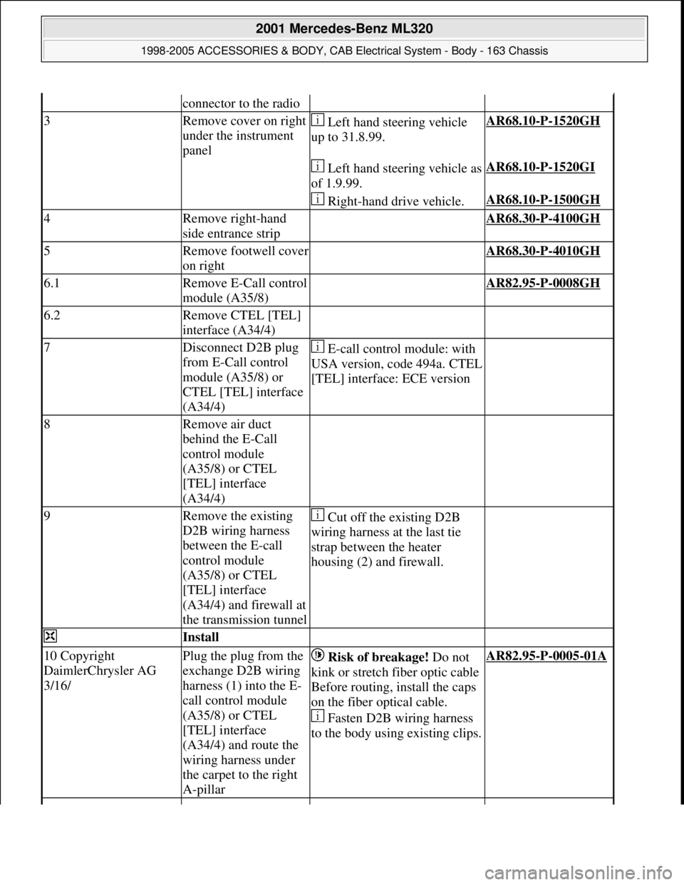
connector to the radio
3Remove cover on right
under the instrument
panel Left hand steering vehicle
up to 31.8.99.AR68.10-P-1520GH
Left hand steering vehicle as
of 1.9.99.AR68.10-P-1520GI
Right-hand drive vehicle.AR68.10-P-1500GH
4Remove right-hand
side entrance strip AR68.30-P-4100GH
5Remove footwell cover
on right AR68.30-P-4010GH
6.1Remove E-Call control
module (A35/8) AR82.95-P-0008GH
6.2Remove CTEL [TEL]
interface (A34/4)
7Disconnect D2B plug
from E-Call control
module (A35/8) or
CTEL [TEL] interface
(A34/4) E-call control module: with
USA version, code 494a. CTEL
[TEL] interface: ECE version
8Remove air duct
behind the E-Call
control module
(A35/8) or CTEL
[TEL] interface
(A34/4)
9Remove the existing
D2B wiring harness
between the E-call
control module
(A35/8) or CTEL
[TEL] interface
(A34/4) and firewall at
the transmission tunnel Cut off the existing D2B
wiring harness at the last tie
strap between the heater
housing (2) and firewall.
Install
10 Copyright
DaimlerChrysler AG
3/16/Plug the plug from the
exchange D2B wiring
harness (1) into the E-
call control module
(A35/8) or CTEL
[TEL] interface
(A34/4) and route the
wiring harness under
the carpet to the right
A-pillar Risk of breakage! Do not
kink or stretch fiber optic cable
Before routing, install the caps
on the fiber optical cable.
Fasten D2B wiring harness
to the body using existing clips.AR82.95-P-0005-01A
2001 Mercedes-Benz ML320
1998-2005 ACCESSORIES & BODY, CAB Electrical System - Body - 163 Chassis
me
Saturday, October 02, 2010 3:30:10 PMPage 311 © 2006 Mitchell Repair Information Company, LLC.
Page 1807 of 4133
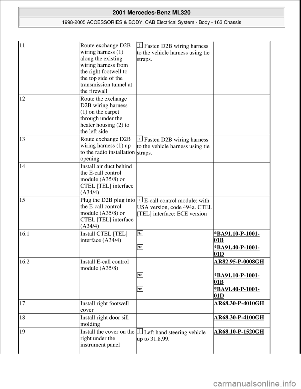
11Route exchange D2B
wiring harness (1)
along the existing
wiring harness from
the right footwell to
the top side of the
transmission tunnel at
the firewall Fasten D2B wiring harness
to the vehicle harness using tie
straps.
12Route the exchange
D2B wiring harness
(1) on the carpet
through under the
heater housing (2) to
the left side
13Route exchange D2B
wiring harness (1) up
to the radio installation
opening Fasten D2B wiring harness
to the vehicle harness using tie
straps.
14Install air duct behind
the E-call control
module (A35/8) or
CTEL [TEL] interface
(A34/4)
15Plug the D2B plug into
the E-call control
module (A35/8) or
CTEL [TEL] interface
(A34/4) E-call control module: with
USA version, code 494a. CTEL
[TEL] interface: ECE version
16.1Install CTEL [TEL]
interface (A34/4) *BA91.10-P-1001-
01B
*BA91.40-P-1001-
01D
16.2Install E-call control
module (A35/8) AR82.95-P-0008GH
*BA91.10-P-1001-
01B
*BA91.40-P-1001-
01D
17Install right footwell
cover AR68.30-P-4010GH
18Install right door sill
molding AR68.30-P-4100GH
19Install the cover on the
right under the
instrument panel Left hand steering vehicle
up to 31.8.99.AR68.10-P-1520GH
2001 Mercedes-Benz ML320
1998-2005 ACCESSORIES & BODY, CAB Electrical System - Body - 163 Chassis
me
Saturday, October 02, 2010 3:30:10 PMPage 312 © 2006 Mitchell Repair Information Company, LLC.