1997 MERCEDES-BENZ ML320 steering
[x] Cancel search: steeringPage 1131 of 4133

327 Index
I
Identification labels 292
Certification label 292
Vehicle identification number
(VIN) 292
Ignition 33
Immobilizer 83
Activating 54, 83
Deactivating 83
Indicator lamp
Adjustable steering column 253
Brake pad wear 254
Coolant 249
Front fog lamps 253
Low engine oil level 253
Indicators, additional
Speedometer display 256
Infant and child restraint systems 68
Installing 71
LATCH child seat mounts 72Information
About service and warranty 10
Button for Tele Aid* 177
Inside rear view mirror
Antiglare 126
Installing
Infant and child restraint systems 71
Wiper blades 273
Instrument cluster 24, 116, 313
Cleaning 238
Coolant temperature gauge 117
Display in the speedometer 117
Illumination 116
Lamps in 252
Outside temperature indicator 118
Instruments and controls see Cockpit 22
Integrated remote control
Erasing memory 185
Operating 185
Interior lighting 112Activating automatic control 113
Deactivating automatic control 113
Manual operation 113
Reading lamps 114
Interior storage spaces 164
Armrest 165
Cup holder 167
Glove box 164
Storage compartment in front of
armrest 165
Storage compartment under front pas-
senger seat* 164
Intermittent wiping 130
J
Jack 258
Jump starting 281
Page 1132 of 4133

328 IndexK
Key
Global locking 89
Global unlocking 89
Loss of 90
Positions in steering lock 33
Remote control with folding key 88
Unlocking liftgate 89
Unlocking the driver’s door, fuel filler
flap 89
Key positions in steering lock 33
Key, Mechanical 261
Key, Remote control
Unlocking with 32
Kickdown 123, 313
L
Labels, identification 292
Lamp bulbs, exterior 266
Lamps, exterior
Front 266
Rear 267Lamps, indicator and warning
4-ETS 251, 252
ABS 242
Adjustable steering column 253
AIRBAG OFF 63, 243
BAS 78, 245, 246, 247
Battery indicator lamp 254
Brake pad wear 254
Brakes 244
CHECK ENGINE 248
Coolant 249
EBP 245
Engine diagnostics 248
ESP 245, 246, 247, 251
Front fog lamps 253
Fuel reserve 252
Low engine oil level 253
LOW RANGE 252
Low washer system fluid level 253
Seat belts 253
Service indicator 232
SRS 255
Turn signals 25LATCH child seat anchors 72
LATCH child seat mounts 72
Layout of poly-V-belt drive 293
Leather upholstery
Cleaning 239
Lever
For cruise control 150
License plate lamps
Replacing bulbs 267, 271
Liftgate
Closing 92
Opening 89, 91
Opening from inside 91
Opening from outside 91
Light alloy wheels
Cleaning 238
Lighter
Rear center console 169
Lighter see cigarette lighter 168
Page 1140 of 4133

336 IndexSide windows 144
Automatic closing 145
Automatic opening 145
Cleaning 237
Closing 145
Closing fully (Express-close) 145
Opening 145
Opening and closing 144
Opening fully (Express-open) 145
Rear quarter window 146
Stopping 145
Synchronizing power windows 146
Simultaneous wiping and washing
Rear window wiper/washer 51
Windshield wipers 50
Single wipe 50
Sliding/pop-up roof* 148
Closing 148, 265
Opening 148, 265
Synchronizing 149
Snow chains 231
Spare fuses 287
Spare parts service 290Spare wheel 259
Mounting 274
Removing 259
Speed
Saving current 151
Speed settings
Cruise control 152
Speedometer 25
Speedometer display
Additional indicators 256
Split rear bench seat 99
SRS 66, 314
Indicator lamp 255
Standing lamps 107
Replacing bulbs 266, 267
Standing water
Driving instructions 200
StArt
Display messages 256
Starting difficulties 47
Starting position 33
Starting the engine 46Steep terrain
Driving 202
Steering column
Height adjustment 39
Length adjustment 39
Steering lock 23, 33
Positions 33
Steering wheel
Adjusting 39
Adjustment 39
Cleaning 238
Stolen vehicle
Tracking services 180
Stop watch 189
Stopping
Windows 145
Storage compartments
Glove box 164
Under front passenger seat* 164
Storing (Memory function*)
Positions into memory 106
Stranded vehicle 286
Page 1144 of 4133

340 IndexUseful features 164
Ashtrays and cigarette lighter 168
Cup holder 166
Electrical outlet 170
Garage door opener 180
Interior storage spaces 164
Programming or reprogramming the in-
tegrated remote control 182
Tele Aid* 171
Telephone* 170
Trip computer* 186
V
Vehicle
Locking 28
Locking in an emergency 262
Lowering 276
Proper use of 17
Service battery 278
Towing 283
Unlocking 28
Unlocking in an emergency 261
Vehicle and trailer weights and
ratings 207
Vehicle battery 278Vehicle care
Cup holder 238
Engine cleaning 236
Gear selector lever 238
Hard plastic trim items 238
Headlamps 236
Instrument cluster 238
Leather upholstery 239
Light alloy wheels 238
MB Tex upholstery 239
Ornamental moldings 236
Paintwork 235
Parktronic* system sensor 237
Plastic and rubber parts 239
Power washer 235
Seat belts 238
Steering wheel 238
Tail lamps 236
Tar stains 235
Turn signals 236
Upholstery 239
Vehicle washing 236
Window cleaning 237
Wiper blades 237Vehicle identification number (VIN) 292
Vehicle jack 258
Vehicle lighting
Checking 216
Vehicle tool kit 257
Vehicle with CD-changer* 258
Vehicle washing 236
VIN (Vehicle Identification Number) 292,
315
Voice control system* 315
W
Warning indicators
Parktronic* 155
Warning sounds
Drivers seat belts 64
Parking brake 48
Warranty coverage 291
Washer fluid see Windshield washer fluid
Washing the vehicle 234
Page 1167 of 4133

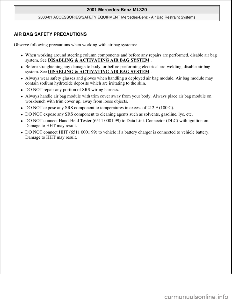
AIR BAG SAFETY PRECAUTIONS
Observe following precautions when working with air bag systems:
When working around steering column components and before any repairs are performed, disable air bag
system. See DISABLING & ACTIVATING AIR BAG SYSTEM
.
Before straightening any damage to body, or before performing electrical arc-welding, disable air bag
system. See DISABLING & ACTIVATING AIR BAG SYSTEM
.
Always wear safety glasses and gloves when handling a deployed air bag module. Air bag module may
contain sodium hydroxide deposits which are irritating to the skin.
DO NOT repair any portion of SRS wiring harness.
Always handle air bag module with trim cover away from your body. Always place air bag module on
workbench with trim cover up, away from loose objects.
DO NOT expose any SRS component to temperatures in excess of 212 F (100 C).
DO NOT expose any SRS component to cleaning agents such as solvents, gasoline, lye, etc.
DO NOT connect Hand-Held Tester (6511 0001 99) to Data Link Connector (DLC) with ignition on.
Damage to HHT may result.
DO NOT connect HHT (6511 0001 99) to vehicle if a battery charger is connected to vehicle battery.
Dama
ge to HHT may result.
2001 Mercedes-Benz ML320
2000-01 ACCESSORIES/SAFETY EQUIPMENT Mercedes-Benz - Air Bag Restraint Systems
2001 Mercedes-Benz ML320
2000-01 ACCESSORIES/SAFETY EQUIPMENT Mercedes-Benz - Air Bag Restraint Systems
me
Saturday, October 02, 2010 3:43:48 PMPage 1 © 2006 Mitchell Repair Information Company, LLC.
me
Saturday, October 02, 2010 3:43:51 PMPage 1 © 2006 Mitchell Repair Information Company, LLC.
Page 1184 of 4133

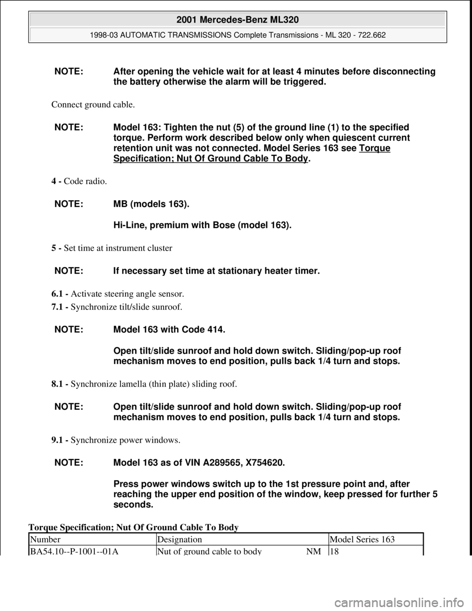
Connect ground cable.
4 - Code radio.
5 - Set time at instrument cluster
6.1 - Activate steering angle sensor.
7.1 - Synchronize tilt/slide sunroof.
8.1 - Synchronize lamella (thin plate) sliding roof.
9.1 - Synchronize power windows.
Torque Specification; Nut Of Ground Cable To Body NOTE: After opening the vehicle wait for at least 4 minutes before disconnecting
the battery otherwise the alarm will be triggered.
NOTE: Model 163: Tighten the nut (5) of the ground line (1) to the specified
torque. Perform work described below only when quiescent current
retention unit was not connected. Model Series 163 see Torque
Specification; Nut Of Ground Cable To Body.
NOTE: MB (models 163).
Hi-Line, premium with Bose (model 163).
NOTE: If necessary set time at stationary heater timer.
NOTE: Model 163 with Code 414.
Open tilt/slide sunroof and hold down switch. Sliding/pop-up roof
mechanism moves to end position, pulls back 1/4 turn and stops.
NOTE: Open tilt/slide sunroof and hold down switch. Sliding/pop-up roof
mechanism moves to end position, pulls back 1/4 turn and stops.
NOTE: Model 163 as of VIN A289565, X754620.
Press power windows switch up to the 1st pressure point and, after
reaching the upper end position of the window, keep pressed for further 5
seconds.
NumberDesignationModel Series 163
BA54.10--P-1001--01ANut of ground cable to bodyNM18
2001 Mercedes-Benz ML320
1998-03 AUTOMATIC TRANSMISSIONS Complete Transmissions - ML 320 - 722.662
me
Saturday, October 02, 2010 3:15:25 PMPage 15 © 2006 Mitchell Repair Information Company, LLC.
Page 1189 of 4133

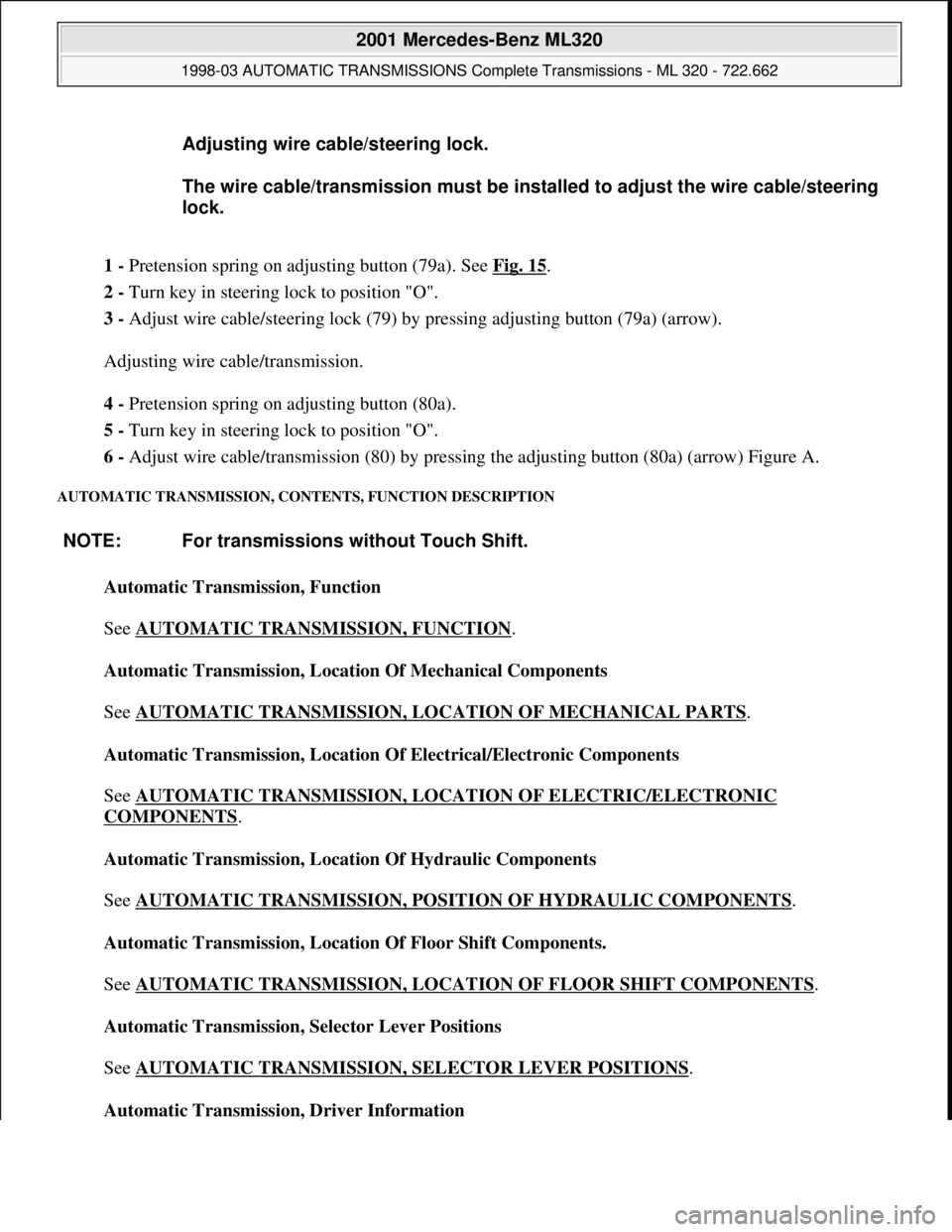
1 - Pretension spring on adjusting button (79a). See Fig. 15.
2 - Turn key in steering lock to position "O".
3 - Adjust wire cable/steering lock (79) by pressing adjusting button (79a) (arrow).
Adjusting wire cable/transmission.
4 - Pretension spring on adjusting button (80a).
5 - Turn key in steering lock to position "O".
6 - Adjust wire cable/transmission (80) by pressing the adjusting button (80a) (arrow) Figure A.
AUTOMATIC TRANSMISSION, CONTENTS, FUNCTION DESCRIPTION
Automatic Transmission, Function
See AUTOMATIC TRANSMISSION, FUNCTION
.
Automatic Transmission, Location Of Mechanical Components
See AUTOMATIC TRANSMISSION, LOCATION OF MECHANICAL PARTS
.
Automatic Transmission, Location Of Electrical/Electronic Components
See AUTOMATIC TRANSMISSION, LOCATION OF ELECTRIC/ELECTRONIC
COMPONENTS.
Automatic Transmission, Location Of Hydraulic Components
See AUTOMATIC TRANSMISSION, POSITION OF HYDRAULIC COMPONENTS
.
Automatic Transmission, Location Of Floor Shift Components.
See AUTOMATIC TRANSMISSION, LOCATION OF FLOOR SHIFT COMPONENTS
.
Automatic Transmission, Selector Lever Positions
See AUTOMATIC TRANSMISSION, SELECTOR LEVER POSITIONS
.
Automatic Transmission, Driver Information Adjusting wire cable/steering lock.
The wire cable/transmission must be installed to adjust the wire cable/steering
lock.
NOTE: For transmissions without Touch Shift.
2001 Mercedes-Benz ML320
1998-03 AUTOMATIC TRANSMISSIONS Complete Transmissions - ML 320 - 722.662
me
Saturday, October 02, 2010 3:15:25 PMPage 20 © 2006 Mitchell Repair Information Company, LLC.
Page 1201 of 4133

Shift-Lock, Function
See SHIFT
-LOCK FUNCTION.
Park Pawl Interlock, Function
See PARK PAWL INTERLOCK, FUNCTION
.
Steering Lock Interlock, Function
See STEERING LOCK INTERLOCK, FUNCTION
.
Survey Of System Components, Automatic Transmission, Location/Task/Design/Function
See SURVEY OF SYSTEM COMPONENTS, AUTOMATIC TRANSMISSION,
LOCATION/TASK/DESIGN/FUNCTION.
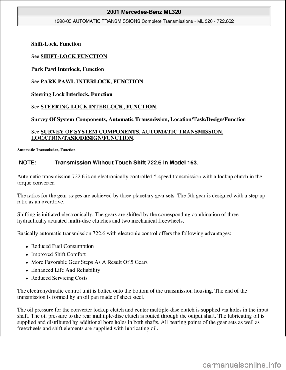
Automatic Transmission, Function
Automatic transmission 722.6 is an electronically controlled 5-speed transmission with a lockup clutch in the
torque converter.
The ratios for the gear stages are achieved by three planetary gear sets. The 5th gear is designed with a step-up
ratio as an overdrive.
Shifting is initiated electronically. The gears are shifted by the corresponding combination of three
hydraulically actuated multi-disc clutches and two mechanical freewheels.
Basically automatic transmission 722.6 with electronic control offers the following advantages:
Reduced Fuel Consumption
Improved Shift Comfort
More Favorable Gear Steps As A Result Of 5 Gears
Enhanced Life And Reliability
Reduced Servicing Costs
The electrohydraulic control unit is bolted onto the bottom of the transmission housing. The end of the
transmission is formed by an oil pan made of sheet steel.
The oil pressure for the converter lockup clutch and center multiple-disc clutch is supplied via holes in the input
shaft. The oil pressure to the rear mulitiple-disc clutch is routed through the output shaft. The lubricating oil is
supplied and distributed by additional bore holes in both shafts. All bearing points of the gear sets as well as
freewheels and shift elements are supplied with lubricatin
g oil. NOTE: Transmission Without Touch Shift 722.6 In Model 163.
2001 Mercedes-Benz ML320
1998-03 AUTOMATIC TRANSMISSIONS Complete Transmissions - ML 320 - 722.662
me
Saturday, October 02, 2010 3:15:25 PMPage 32 © 2006 Mitchell Repair Information Company, LLC.