Page 309 of 4133

259 Towing
Te ch n ica l
data Instruments
and controlsOperation DrivingInstrument
cluster displayPractical hintsCar care Index Transmission selector lever, manually unlocking
In the case of power failure the transmission selector
lever can be manually unlocked, e.g. to tow the vehicle.
To do so, insert a pin (1), e.g. ball point pen, into the
covered opening below the position “D” of the shift
pattern. While pushing the pin down, move selector
lever from position “P”.
After removal of the pin from the opening, the cover will
not close fully. Only after moving the selector lever to
positions “D+” and “D–” does the cover return to its
closed position.Stranded vehicle
Freeing a stranded vehicle, on which the wheels are dug
into sand or mud, should be done with the greatest of
care, especially if the vehicle is heavily loaded.
Avoid pulling the vehicle jerkily or diagonally, since it
could result in damage to the chassis alignment.
Never try to free a vehicle that is still coupled to a
trailer.
If possible, a vehicle equipped with trailer hitch receiver
should be pulled backward in its own previously made
tracks.
Page 726 of 4133

259
Towing
Te ch n ica l
data
Instruments
and controls Operation Driving
Instrument
cluster display Practical hints
Car care Index
Transmission selector lever, manually unlocking
In the case of power failure the transmission selector
lever can be manually unlocked, e.g. to tow the vehicle.
To do so, insert a pin (1), e.g. ball point pen, into the
covered opening below the position “D” of the shift
pattern. While pushing the pin down, move selector
lever from position “P”.
After removal of the pin from the opening, the cover will
not close fully. Only after moving the selector lever to
positions “D+” and “D–” does the cover return to its
closed position. Stranded vehicle
Freeing a stranded vehicle, on which the wheels are dug
into sand or mud, should be done with the greatest of
care, especially if the vehicle is heavily loaded.
Avoid pulling the vehicle jerkily or diagonally, since it
could result in damage to the chassis alignment.
Never try to free a vehicle that is still coupled to a
trailer.
If possible, a vehicle equipped with trailer hitch receiver
should be pulled backward in its own previously made
tracks.
Page 1090 of 4133
286 Practical hintsTowing the vehicleVehicles with sport package*1Cover
2Towing eye
To remove cover:�
Grip cover1 at bottom and securely
pull out.
To reinstall cover:
�
Engage cover and press in securely.
Stranded vehicle
Freeing a stranded vehicle, on which the
wheels are dug into sand or mud, should
be done with the greatest of care, especial-
ly if the vehicle is heavily loaded.
Avoid pulling the vehicle jerkily or diago-
nally, since it could result in damage to the
chassis alignment.
Never try to free a vehicle that is still cou-
pled to a trailer.
If possible, a vehicle equipped with trailer
hitch receiver should be pulled backward
in its own previously made tracks.
Page 2526 of 4133

Front axle carrier
Wheel control, hub
Front axle torsion strut
Propeller shaft of front axle gear
Use original bolts
only.
Do not position bolts
at an angle when
screwing in.
Do not use an impact
wrench.
Observe the
tightening torque.
*BA33.10-P-1001-01C
21Lower front axle carrier
(1), pushing all hoses to
one side Installation: Contact
surfaces of front axle
carrier to longitudinal
member must be cleaned
and flat.
Insert the locating pins of
the front axle carrier into
the holes in the side
member.
22Check front axle carrier
(1) for damage
23Install in the reverse order
24Fill power steering pump
and bleedEngine 112, 113AR46.30-P-0010B
Engine 111, 612AR46.30-P-0010P
25Bleed brake system AR42.10-P-0010GH
26Perform chassis
alignment AR40.20-P-0200GH
NumberDesignationModel Series 163
BA33.10-P-1001-01CBolt of front axle carrier to frameNm200
NumberDesignationModel Series 163
BA33.20-P-1006-01DBolt, upper transverse control arm to frameNm120
NumberDesignationModel Series 163
BA32.20-P-1001-02GBolt, retaining bracket to frameNm100
NumberDesignationModel Series 163
2001 Mercedes-Benz ML320
1998-2005 DRIVELINE/AXLES Front Axle - 163 Chassis
me
Saturday, October 02, 2010 3:38:21 PMPage 7 © 2006 Mitchell Repair Information Company, LLC.
Page 2534 of 4133

Front axle torsion bar
Wheel location, hub
Front axle shaft
Brake lines, brake hoses
Brake lines, brake hoses
Track rod
*BA33.20-P-1005-01D
16Install in the reverse order
17Bleed brake system AR42.10-P-0010GH
18Carry out chassis
alignment check. AR40.20-P-0200GH
NumberDesignationModel 163
BA32.20-P-1002-02GBolt, torsion bar to transverse control armNm68
NumberDesignationModel 163
BA33.20-P-1004-01DBolt, lower transverse control arm at front to front axle carrierNm135
BA33.20-P-1005-01DBolt, lower transverse control arm at rear to front axle carrierNm30
BA33.20-P-1006-01DBolt, upper transverse control arm to frameNm120
NumberDesignationModel 163
BA33.30-P-1001-02BNut, front axle shaft to front axle shaft flangeNm490
NumberDesignationModel 163.113 as
of VIN A289565,
X754620 163.154 as
of VIN A289565Model 163.113 to
VIN A289564,
X754619 163.154 to
VIN A289564
BA42.10-P-1001-
04ABrake line to brake
hoseNm1818
NumberDesignationModel
163.128 /172 /174 /175Model
163.136Model
163.154 /157
BA42.10-P-1001-
04ABrake line to brake
hoseNm181818
NumberDesignationModel 163
BA46.40-P-1001-01CSelf-locking nut, track rod to steering knuckleNm55
2001 Mercedes-Benz ML320
1998-2005 DRIVELINE/AXLES Front Axle - 163 Chassis
me
Saturday, October 02, 2010 3:38:22 PMPage 15 © 2006 Mitchell Repair Information Company, LLC.
Page 2551 of 4133
Wheel location, hub
Fig. 50: Identifying Press (163 589 03 43 00)
Fig. 51: Identifying Support (163 589 01 43 00)
6Detach upper transverse control
arm (6) from vehicle frame
Installation: Gently tighten the new nuts,
continuing until they seat. Wait until the
vehicle is resting on it s road wheels before
tightening the bolts.
*BA33.20-P-
1006-01D
7Install in the reverse order
8Perform chassis alignment check AR40.20-P-
0200GH
NumberDesignationModel Series
163
BA33.20-P-1001-
01DSelf-locking nut, upper wishbone follower joint to steering
knuckleNM50
BA33.20-P-1006-
01DBolt, upper wishbone to frameNM120
2001 Mercedes-Benz ML320
1998-2005 DRIVELINE/AXLES Front Axle - 163 Chassis
me
Saturday, October 02, 2010 3:38:22 PMPage 32 © 2006 Mitchell Repair Information Company, LLC.
Page 2553 of 4133

Front axle torsion strut
Wheel location, hub
REPLACE FRONT BEARING OF LOWER WISHBONE - AR33.20-P-0526GH
MODEL 163.113 /128 /136 /154 /157 /172 /174 /175
3.1
Remove linkage rod for suspension-
control module (95b) from lower
right control arm
Vehicles with xenon headlamps.
4Detach torsion bar (28) from lower
control arm *BA32.20-P-
1002-02G
5Detach lower control arm (4) from
front subframe
Installation: Tighten new nuts slightly.
Tighten bolt fully only when vehicle is on
its wheels and ready to drive.
*BA33.20-P-
1004-01D
6
Loosen clamped joint at rear of
lower wishbone (4) and fold down
bearing shell (4d)
Installation: Tighten new nuts slightly.
Tighten bolt fully only when vehicle is on
its wheels and ready to drive.
*BA33.20-P-
1005-01D
Inspect
7Inspect lower control arm for signs
of distortion and corrosion
8Install in the reverse order
9Perform chassis alignment check AR40.20-P-
0200GH
NumberDesignationModel Series 163
BA32.20-P-1002-02GBolt, torsion bar to wishboneNM68
NumberDesignationModel Series 163
BA33.20-P-1004-01DBolt, lower wishbone at front to front axle carrierNM135
BA33.20-P-1005-01DBolt, lower wishbone at rear to front axle carrierNM30
2001 Mercedes-Benz ML320
1998-2005 DRIVELINE/AXLES Front Axle - 163 Chassis
me
Saturday, October 02, 2010 3:38:22 PMPage 34 © 2006 Mitchell Repair Information Company, LLC.
Page 2556 of 4133
 from
steering knuckle
Check rubber boot and ball joint for wear and
damage.AR")
Wheel location, hub
5
Remove rpm sensor with
bracket from steering
knuckle
AR42.30-P-
0712GH
6Detach tie rod (10) from
steering knuckle
Check rubber boot and ball joint for wear and
damage.AR46.40-P-
0200-02C
*BA46.40-P-
1001-01C
Thrust pieceFig. 16
PullerFig. 58
7
Press out follower joint
from upper transverse
control arm (6) using puller
Check rubber boot and ball joint for wear and
damage.AR33.20-P-
0500-01GH
*BA33.20-P-
1001-01D
Thrust pieceFig. 45
SupportFig. 46
PressFig. 47
8Press front axle shaft out of
front axle shaft flange AR33.30-P-
0620-04GH
Extraction and insertion toolFig. 18
9Press supporting joint off
lower wishbone
Secure steering knuckle to prevent it from falling
down, in order to rule out damage to the steering
knuckle
Check rubber boot and ball joint for wear and
damage.
AR33.20-P-
0440-02GH
*BA33.20-P-
1002-01D
Thrust pieceFig. 16
10Remove steering knuckle
(5) forwards
Check
11Check supporting joint
Inspect front axle joint for
play, inspect rubber bootsAP33.20-P-
3353GH
12Install in the reverse order
13.1Perform chassis alignment
check After installation of new parts.AR40.20-P-
0200GH
NumberDesignationModel 163
BA33.20-P-1001-01DSelf-locking nut, upper wishbone follower joint to steering knuckleNm50
BA33.20-P-1002-01DSelf-locking nut, supporting joint to steering knuckleNm85
2001 Mercedes-Benz ML320
1998-2005 DRIVELINE/AXLES Front Axle - 163 Chassis
me
Saturday, October 02, 2010 3:38:22 PMPage 37 © 2006 Mitchell Repair Information Company, LLC.
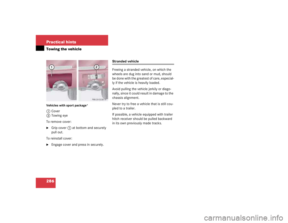

Fig. 51: Identifying Support (163 589 01 43 00)
6Detach upper transverse control
arm (6) from vehicle frame
Installation:")