Page 432 of 4133
TORQUE SPECIFICATIONS
TORQUE SPECIFICATIONS
(1)
WIRING DIAGRAMS
ApplicationFt. Lbs (N.m)
Steering wheel hub bolt52-66 (70-90)
INCH Lbs. (N.m)
Driver air bag module bolts (torx)44-62 (5-7)
(1)Torque specifications are not av ailable for clockspring assembly, control module or passenger-side
air bag module.
2001 Mercedes-Benz ML320
2000-01 ACCESSORIES/SAFETY EQUIPMENT Merc edes-Benz - Air Bag Restraint Systems
me
Saturday, October 02, 2010 3:44:46 PMPage 68 © 2006 Mitchell Repair Information Company, LLC.
Page 800 of 4133
Courtesy of MERCEDES-BENZ OF NORTH AMERICA.
WIRE REPAIR
DO NOT repair wiring harness. Replace complete SRS wiring harn ess, if any part is damaged.
TORQUE SPECIFICATIONS
TORQUE SPECIFICATIONS
DIAGNOSTICS
Air bag system diagnostic information is not available. All air bag system diagnosis must be carried out using
manufacturers proprietary STAR diagnostic tool.
WIRING DIAGRAMS
ApplicationFt. Lbs. (N.m)
Front ETR
Belt end fitting26 (35)
Belt height adjuster bolt18 (25)
Bolts22 (30)
Rear ETR
Belt height adjuster bolt22 (30)
Bolts22 (30)
INCH Lbs. (N.m)
Control module bolts(1)
Driver-side air bag module bolts71 (8)
Head impact air bag module bolts71 (8)
Passenger-side air bag module nuts71 (8)
Side impact sensor screws(1)
(1)Information is not available.
2004 Mercedes-Benz ML350
2004 ACCESSORIES/SAFETY EQUIPMENT Merce des-Benz - Air Bag Restraint Systems
me
Saturday, October 02, 2010 3:40:40 PMPage 15 © 2006 Mitchell Repair Information Company, LLC.
Page 1163 of 4133
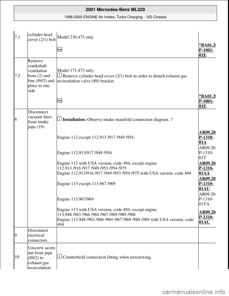
7.1cylinder head
cover (2/1) boltModel 230.475 only
*BA01.20
P-1001-
01E
7.2
Remove
crankshaft
ventilation
hose (2) and
line (89/2) and
place to one
side
Model 171.473 only
Remove cylinder head cover (2/1) bolt in order to detach exhaust gas
recirculation valve (89) bracket.
*BA01.20
P-1001-
01E
8
Disconnect
vacuum lines
from intake
pipe (19)
Installation: Observe intake manifold connection diagram. ?
Engine 112 except 112.913 /917 /949 /954AR09.20
-
P-1310-
01A
Engine 112.913/917 /949 /954AR09.20
-
P-1310-
01T
Engine 112 with USA version, code 494, except engine
112.913 /916 /917 /949 /953 /954 /975
Engine 112.913/916 /917 /949 /953 /954 /975 with USA version, code 494AR09.20-
P-1310-
01AA
Engine 113 except 113.967 /969AR09.20
-
P-1310-
01AU
Engine 113.967/969AR09.20
-
P-1310-
01TA
Engine 113 with USA version, code 494, except engine
113.948 /963 /966 /984 /967 /969 /989 /988
Engine 113.948 /963 /966 /984 /967 /969 /988 /989 with USA version, code
494AR09.20-
P-1310-
01AC
9
Disconnect
electrical
connectors
10
Unscrew acorn
nut from pipe
(89/2) to
exhaust gas
recirculation
Counterhold connection fitting when unscrewing.
2001 Mercedes-Benz ML320
1998-2005 ENGINE Air Intake, Turbo Charging - 163 Chassis
me
Saturday, October 02, 2010 3:16:57 PMPage 12 © 2006 Mitchell Repair Information Company, LLC.
Page 2060 of 4133
TORQUE SPECIFICATIONS
TORQUE SPECIFICATIONS
WIRING DIAGRAMS
See CHARGING SYSTEM in appropriate SYSTEM WIRING DIAGRAMS article in ELECTRICAL.
ApplicationFt. Lbs. (N.m)
Generator Mounting Bolts30 (42)
Generator Pulley Nut52 (70)
2001 Mercedes-Benz ML320
2001-04 STARTING & CHARGING SYSTEMS Generators & Regulators - 163 Chassis
me
Saturday, October 02, 2010 3:20:32 PMPage 26 © 2006 Mitchell Repair Information Company, LLC.
Page 2245 of 4133
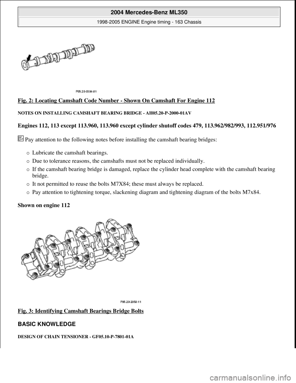
Fig. 2: Locating Camshaft Code Number - Shown On Camshaft For Engine 112
NOTES ON INSTALLING CAMSHAFT BEARING BRIDGE - AH05.20-P-2000-01AV
Engines 112, 113 except 113.960, 113.960 except cylind er shutoff codes 479, 113.962/982/993, 112.951/976
Pay attention to the following notes before installing the camshaft bearing bridges:
Lubricate the camshaft bearings.
Due to tolerance reasons, the camshafts must not be replaced individually.
If the camshaft bearing bridge is damaged, replace th e cylinder head complete with the camshaft bearing
bridge.
It not permitted to reuse the bolts M7 X84; these must always be replaced.
Pay attention to tightening torque, slackening di agram and tightening diagram of the bolts M7x84.
Shown on engine 112
Fig. 3: Identifying Camshaft Bearings Bridge Bolts
BASIC KNOWLEDGE
DESIGN OF CHAIN TENS IONER - GF05.10-P-7801-01A
2004 Mercedes-Benz ML350
1998-2005 ENGINE Engine timing - 163 Chassis
me
Saturday, October 02, 2010 3:39:37 PMPage 4 © 2006 Mitchell Repair Information Company, LLC.
Page 2313 of 4133
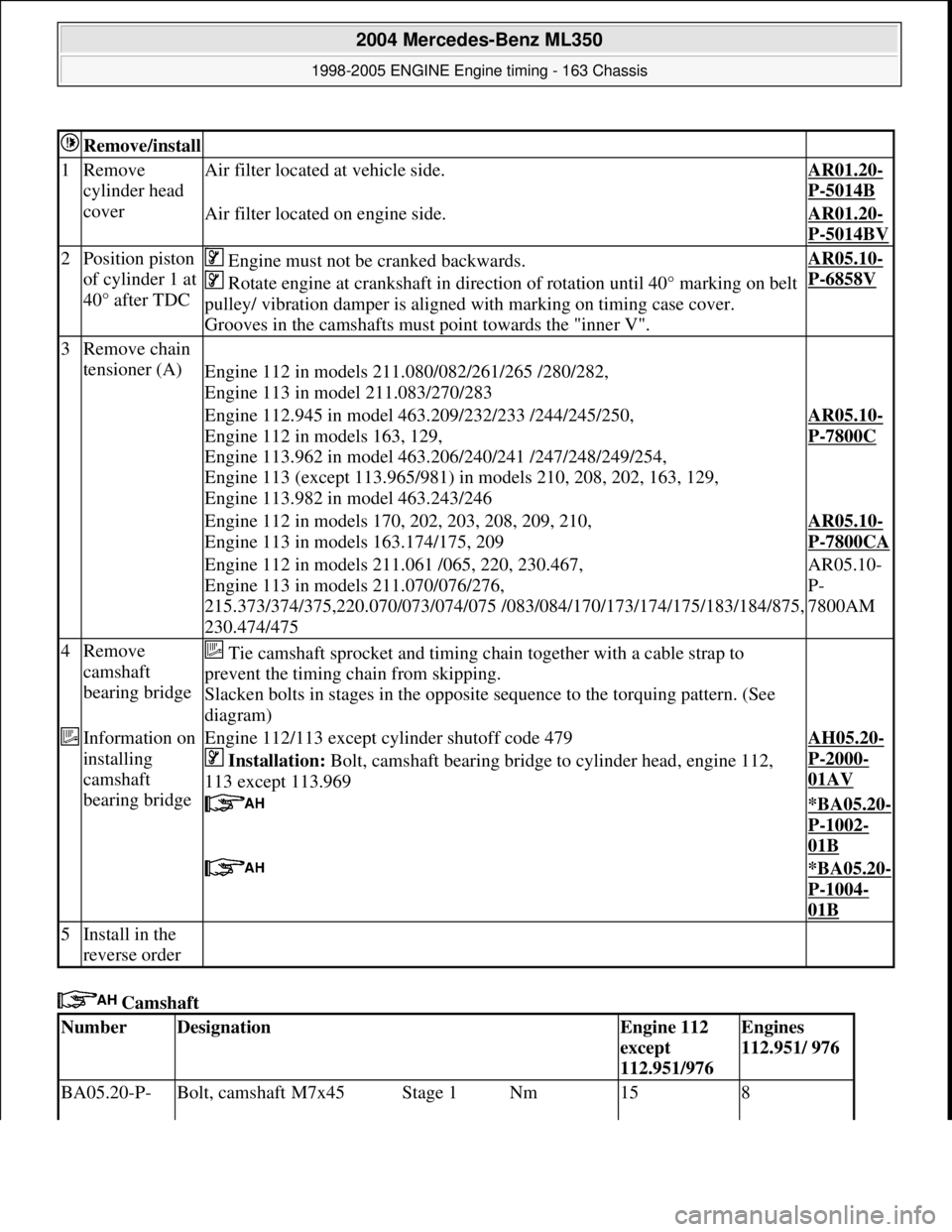
Camshaft
Remove/install
1Remove
cylinder head
coverAir filter located at vehicle side.AR01.20-
P-5014B
Air filter located on engine side.AR01.20-
P-5014BV
2Position piston
of cylinder 1 at
40° after TDC Engine must not be cranked backwards.
Rotate engine at crankshaft in direct ion of rotation until 40° marking on belt
pulley/ vibration damper is aligned with marking on timing case cover.
Grooves in the camshafts must point towards the "inner V".AR05.10-
P-6858V
3Remove chain
tensioner (A)
Engine 112 in models 211.080/082/261/265 /280/282,
Engine 113 in model 211.083/270/283
Engine 112.945 in model 463.209/232/233 /244/245/250,
Engine 112 in models 163, 129,
Engine 113.962 in model 463.206/240/241 /247/248/249/254,
Engine 113 (except 113.965/981) in models 210, 208, 202, 163, 129,
Engine 113.982 in model 463.243/246AR05.10-
P-7800C
Engine 112 in models 170, 202, 203, 208, 209, 210,
Engine 113 in models 163.174/175, 209AR05.10-
P-7800CA
Engine 112 in models 211.061 /065, 220, 230.467,
Engine 113 in models 211.070/076/276,
215.373/374/375,220.070/073/074/075 /083/ 084/170/173/174/175/183/184/875,
230.474/475AR05.10-
P-
7800AM
4Remove
camshaft
bearing bridge Tie camshaft sprocket and timing ch ain together with a cable strap to
prevent the timing chain from skipping.
Slacken bolts in stages in the opposite sequence to the torquing pattern. (See
diagram)
Information on
installing
camshaft
bearing bridgeEngine 112/113 except cylinder shutoff code 479
Installation: Bolt, camshaft bearing bridge to cylinder head, engine 112,
113 except 113.969AH05.20-
P-2000-
01AV
*BA05.20-
P-1002-
01B
*BA05.20-
P-1004-
01B
5Install in the
reverse order
NumberDesignationEngine 112
except
112.951/976Engines
112.951/ 976
BA05.20-P- Bolt, camshaft M7x45Stage 1Nm158
2004 Mercedes-Benz ML350
1998-2005 ENGINE Engine timing - 163 Chassis
me
Saturday, October 02, 2010 3:39:38 PMPage 72 © 2006 Mitchell Repair Information Company, LLC.
Page 2363 of 4133
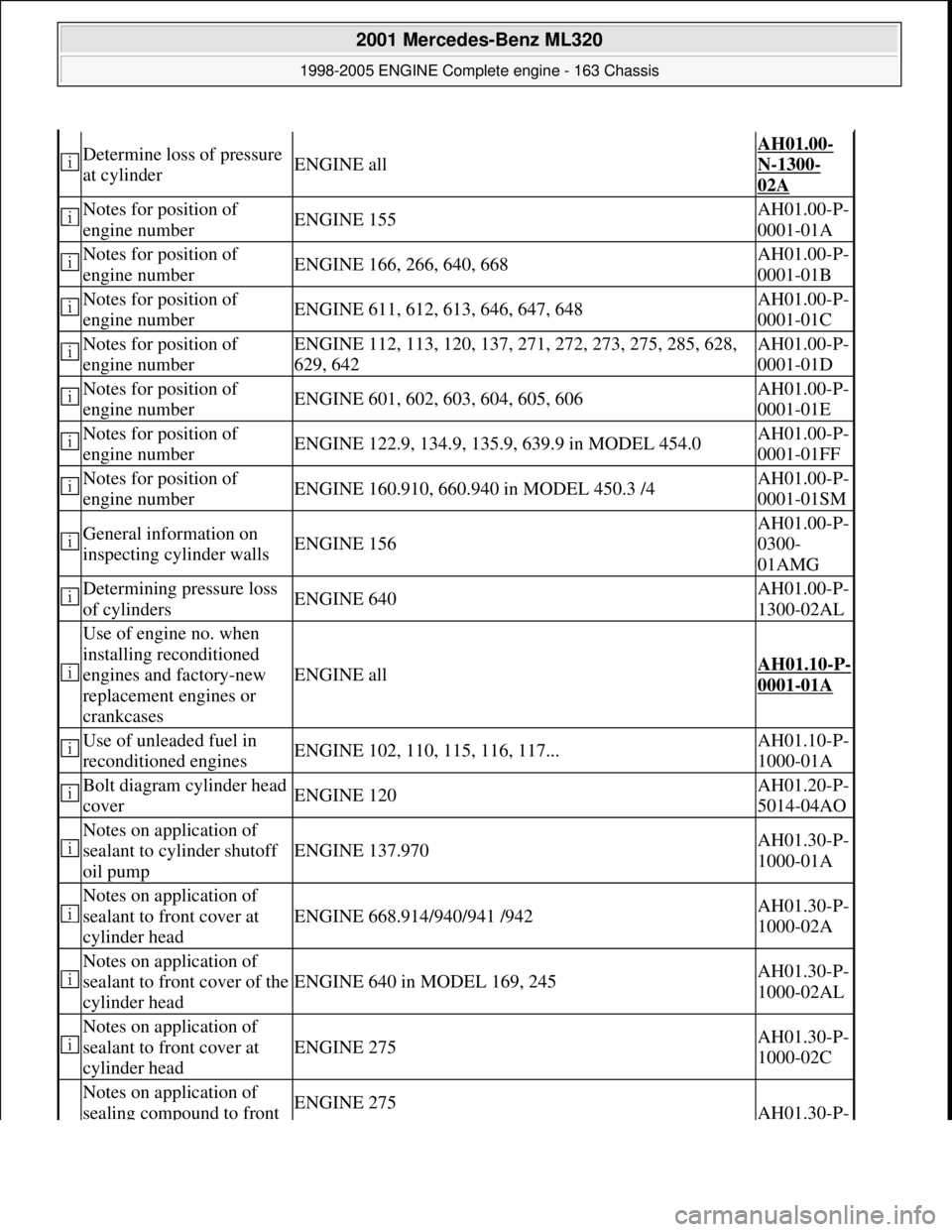
Determine loss of pressure
at cylinderENGINE all
AH01.00-
N-1300-
02A
Notes for position of
engine numberENGINE 155AH01.00-P-
0001-01A
Notes for position of
engine numberENGINE 166, 266, 640, 668AH01.00-P-
0001-01B
Notes for position of
engine numberENGINE 611, 612, 613, 646, 647, 648AH01.00-P-
0001-01C
Notes for position of
engine numberENGINE 112, 113, 120, 137, 271, 272, 273, 275, 285, 628,
629, 642AH01.00-P-
0001-01D
Notes for position of
engine numberENGINE 601, 602, 603, 604, 605, 606AH01.00-P-
0001-01E
Notes for position of
engine numberENGINE 122.9, 134.9, 135.9, 639.9 in MODEL 454.0AH01.00-P-
0001-01FF
Notes for position of
engine numberENGINE 160.910, 660.940 in MODEL 450.3 /4AH01.00-P-
0001-01SM
General information on
inspecting cylinder wallsENGINE 156
AH01.00-P-
0300-
01AMG
Determining pressure loss
of cylindersENGINE 640AH01.00-P-
1300-02AL
Use of engine no. when
installing reconditioned
engines and factory-new
replacement engines or
crankcases
ENGINE allAH01.10-P-
0001-01A
Use of unleaded fuel in
reconditioned enginesENGINE 102, 110, 115, 116, 117...AH01.10-P-
1000-01A
Bolt diagram cylinder head
coverENGINE 120AH01.20-P-
5014-04AO
Notes on application of
sealant to cylinder shutoff
oil pump
ENGINE 137.970AH01.30-P-
1000-01A
Notes on application of
sealant to front cover at
cylinder head
ENGINE 668.914/940/941 /942AH01.30-P-
1000-02A
Notes on application of
sealant to front cover of the
cylinder head
ENGINE 640 in MODEL 169, 245AH01.30-P-
1000-02AL
Notes on application of
sealant to front cover at
cylinder head
ENGINE 275AH01.30-P-
1000-02C
Notes on application of
sealing compound to front ENGINE 275AH01.30-P-
2001 Mercedes-Benz ML320
1998-2005 ENGINE Complete engine - 163 Chassis
me
Saturday, October 02, 2010 3:17:55 PMPage 7 © 2006 Mitchell Repair Information Company, LLC.
Page 2436 of 4133
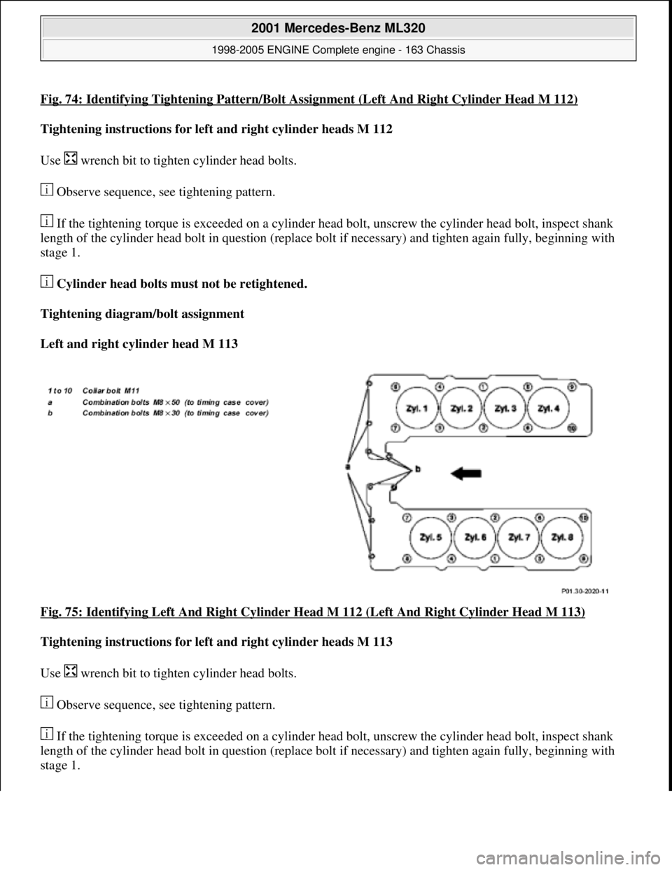
Fig. 74: Identifying Tightening Pattern/Bolt Assignment (Left And Right Cylinder Head M 112)
Tightening instructions for left and right cylinder heads M 112
Use wrench bit to tight en cylinder head bolts.
Observe sequence, see tightening pattern.
If the tightening torque is exceeded on a cylinder he ad bolt, unscrew the cylinder head bolt, inspect shank
length of the cylinder head bolt in question (replace bolt if necessary) and tighten again fully, beginning with
stage 1.
Cylinder head bolts must not be retightened.
Tightening diagram/bolt assignment
Left and right cylinder head M 113
Fig. 75: Identifying Left And Right Cylinder Head M 112 (Left And Right Cylinder Head M 113)
Tightening instructions for left and right cylinder heads M 113
Use wrench bit to tight en cylinder head bolts.
Observe sequence, see tightening pattern.
If the tightening torque is exceeded on a cylinder he ad bolt, unscrew the cylinder head bolt, inspect shank
length of the cylinder head bolt in question (replace bolt if necessary) and tighten again fully, beginning with
stage 1.
2001 Mercedes-Benz ML320
1998-2005 ENGINE Complete engine - 163 Chassis
me
Saturday, October 02, 2010 3:17:56 PMPage 80 © 2006 Mitchell Repair Information Company, LLC.