1997 MERCEDES-BENZ ML320 steering
[x] Cancel search: steeringPage 2035 of 4133
2001-04 STARTING & CHARGING SYSTEMS
Generators & Regulators - 163 Chassis
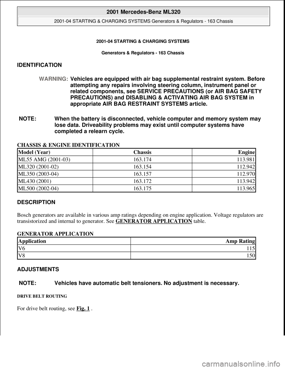
IDENTIFICATION
CHASSIS & ENGINE IDENTIFICATION
DESCRIPTION
Bosch generators are available in various amp ratings depending on engine application. Voltage regulators are
transistorized and internal to generator. See GENERATOR APPLICATION
table.
GENERATOR APPLICATION
ADJUSTMENTS
DRIVE BELT ROUTING
For drive belt routing, see Fig. 1 . WARNING:Vehicles are equipped with air bag supplemental restraint system. Before
attempting any repairs involving steering column, instrument panel or
related components, see SERVICE PRECAUTIONS (or AIR BAG SAFETY
PRECAUTIONS) and DISABLING & ACTIVATING AIR BAG SYSTEM in
appropriate AIR BAG RESTRAINT SYSTEMS article.
NOTE: When the battery is disconnected, vehicle computer and memory system may
lose data. Driveability problems may exist until computer systems have
completed a relearn cycle.
Model (Year)ChassisEngine
ML55 AMG (2001-03)163.174113.981
ML320 (2001-02)163.154112.942
ML350 (2003-04)163.157112.970
ML430 (2001)163.172113.942
ML500 (2002-04)163.175113.965
ApplicationAmp Rating
V6115
V8150
NOTE: Vehicles have automatic belt tensioners. No adjustment is necessary.
2001 Mercedes-Benz ML320
2001-04 STARTING & CHARGING SYSTEMS Generators & Regulators - 163 Chassis
2001 Mercedes-Benz ML320
2001-04 STARTING & CHARGING SYSTEMS Generators & Regulators - 163 Chassis
me
Saturday, October 02, 2010 3:20:31 PMPage 1 © 2006 Mitchell Repair Information Company, LLC.
me
Saturday, October 02, 2010 3:20:35 PMPage 1 © 2006 Mitchell Repair Information Company, LLC.
Page 2042 of 4133
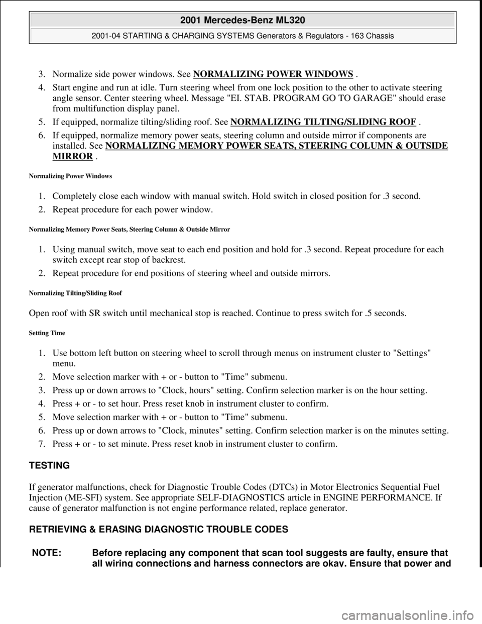
3. Normalize side power windows. See NORMALIZING POWER WINDOWS .
4. Start engine and run at idle. Turn steering wheel from one lock position to the other to activate steering
angle sensor. Center steering wheel. Message "EI. STAB. PROGRAM GO TO GARAGE" should erase
from multifunction display panel.
5. If equipped, normalize tilting/sliding roof. See NORMALIZING TILTING/SLIDING ROOF
.
6. If equipped, normalize memory power seats, steering column and outside mirror if components are
installed. See NORMALIZING MEMORY POWER SEATS, STEERING COLUMN & OUTSIDE
MIRROR .
Normalizing Power Windows
1. Completely close each window with manual switch. Hold switch in closed position for .3 second.
2. Repeat procedure for each power window.
Normalizing Memory Power Seats, Steering Column & Outside Mirror
1. Using manual switch, move seat to each end position and hold for .3 second. Repeat procedure for each
switch except rear stop of backrest.
2. Repeat procedure for end positions of steering wheel and outside mirrors.
Normalizing Tilting/Sliding Roof
Open roof with SR switch until mechanical stop is reached. Continue to press switch for .5 seconds.
Setting Time
1. Use bottom left button on steering wheel to scroll through menus on instrument cluster to "Settings"
menu.
2. Move selection marker with + or - button to "Time" submenu.
3. Press up or down arrows to "Clock, hours" setting. Confirm selection marker is on the hour setting.
4. Press + or - to set hour. Press reset knob in instrument cluster to confirm.
5. Move selection marker with + or - button to "Time" submenu.
6. Press up or down arrows to "Clock, minutes" setting. Confirm selection marker is on the minutes setting.
7. Press + or - to set minute. Press reset knob in instrument cluster to confirm.
TESTING
If generator malfunctions, check for Diagnostic Trouble Codes (DTCs) in Motor Electronics Sequential Fuel
Injection (ME-SFI) system. See appropriate SELF-DIAGNOSTICS article in ENGINE PERFORMANCE. If
cause of generator malfunction is not engine performance related, replace generator.
RETRIEVING & ERASING DIAGNOSTIC TROUBLE CODES
NOTE: Before replacing any component that scan tool suggests are faulty, ensure that
all wiring connections and harness connectors are okay. Ensure that power and
2001 Mercedes-Benz ML320
2001-04 STARTING & CHARGING SYSTEMS Generators & Regulators - 163 Chassis
me
Saturday, October 02, 2010 3:20:32 PMPage 8 © 2006 Mitchell Repair Information Company, LLC.
Page 2143 of 4133
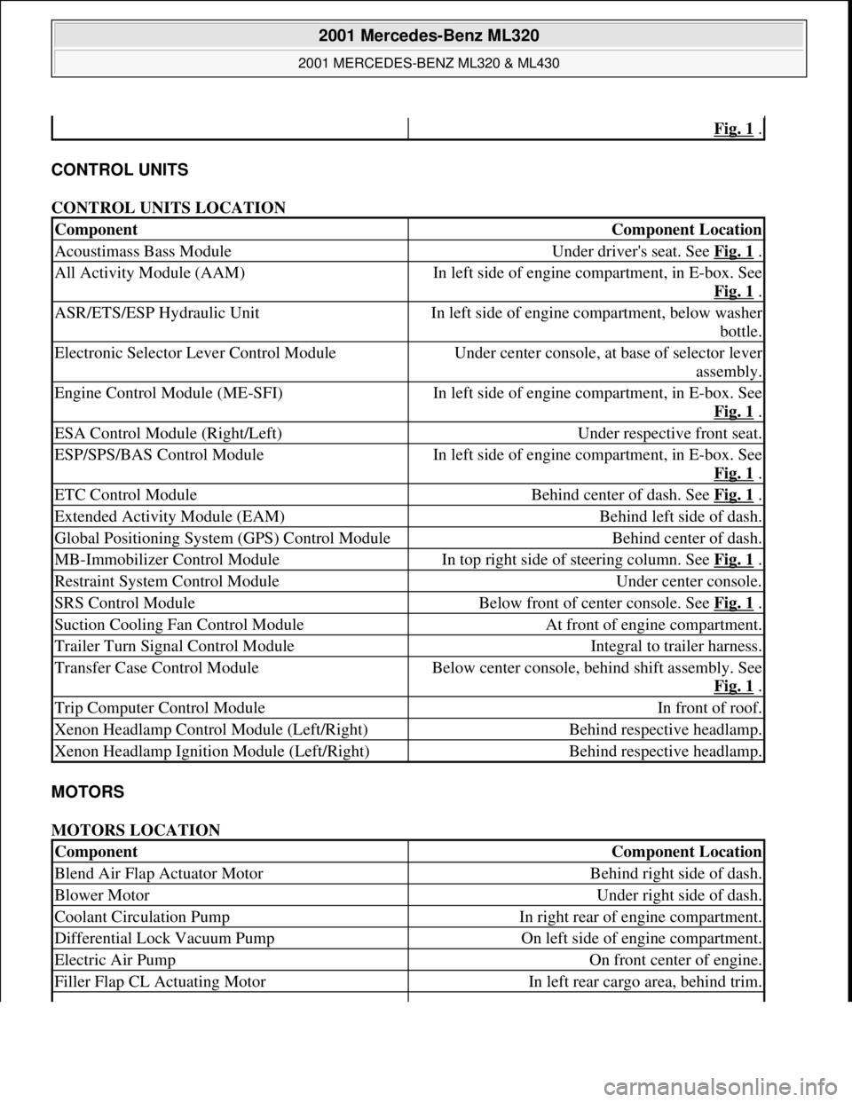
CONTROL UNITS
CONTROL UNITS LOCATION
MOTORS
MOTORS LOCATION
Fig. 1 .
ComponentComponent Location
Acoustimass Bass ModuleUnder driver's seat. See Fig. 1 .
All Activity Module (AAM)In left side of engine compartment, in E-box. See
Fig. 1
.
ASR/ETS/ESP Hydraulic UnitIn left side of engine compartment, below washer
bottle.
Electronic Selector Lever Control ModuleUnder center console, at base of selector lever
assembly.
Engine Control Module (ME-SFI)In left side of engine compartment, in E-box. See
Fig. 1
.
ESA Control Module (Right/Left)Under respective front seat.
ESP/SPS/BAS Control ModuleIn left side of engine compartment, in E-box. See
Fig. 1
.
ETC Control ModuleBehind center of dash. See Fig. 1 .
Extended Activity Module (EAM)Behind left side of dash.
Global Positioning System (GPS) Control ModuleBehind center of dash.
MB-Immobilizer Control ModuleIn top right side of steering column. See Fig. 1 .
Restraint System Control ModuleUnder center console.
SRS Control ModuleBelow front of center console. See Fig. 1 .
Suction Cooling Fan Control ModuleAt front of engine compartment.
Trailer Turn Signal Control ModuleIntegral to trailer harness.
Transfer Case Control ModuleBelow center console, behind shift assembly. See
Fig. 1
.
Trip Computer Control ModuleIn front of roof.
Xenon Headlamp Control Module (Left/Right)Behind respective headlamp.
Xenon Headlamp Ignition Module (Left/Right)Behind respective headlamp.
ComponentComponent Location
Blend Air Flap Actuator MotorBehind right side of dash.
Blower MotorUnder right side of dash.
Coolant Circulation PumpIn right rear of engine compartment.
Differential Lock Vacuum PumpOn left side of engine compartment.
Electric Air PumpOn front center of engine.
Filler Flap CL Actuating MotorIn left rear cargo area, behind trim.
2001 Mercedes-Benz ML320
2001 MERCEDES-BENZ ML320 & ML430
me
Saturday, October 02, 2010 3:21:17 PMPage 3 © 2006 Mitchell Repair Information Company, LLC.
Page 2145 of 4133
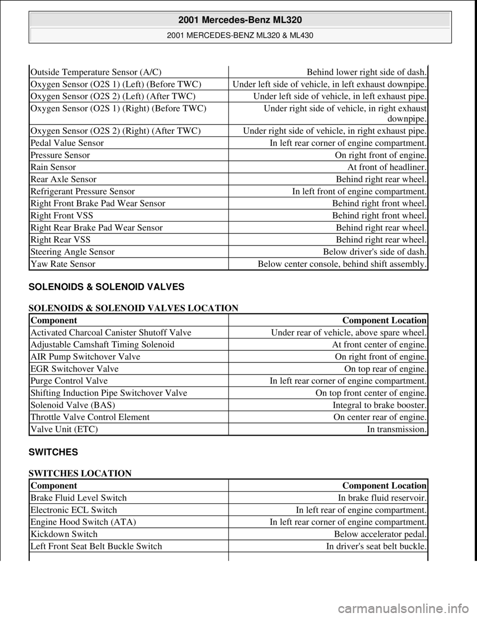
SOLENOIDS & SOLENOID VALVES
SOLENOIDS & SOLENOID VALVES LOCATION
SWITCHES
SWITCHES LOCATION
Outside Temperature Sensor (A/C)Behind lower right side of dash.
Oxygen Sensor (O2S 1) (Left) (Before TWC)Under left side of vehicle, in left exhaust downpipe.
Oxygen Sensor (O2S 2) (Left) (After TWC)Under left side of vehicle, in left exhaust pipe.
Oxygen Sensor (O2S 1) (Right) (Before TWC)Under right side of vehicle, in right exhaust
downpipe.
Oxygen Sensor (O2S 2) (Right) (After TWC)Under right side of vehicle, in right exhaust pipe.
Pedal Value SensorIn left rear corner of engine compartment.
Pressure SensorOn right front of engine.
Rain SensorAt front of headliner.
Rear Axle SensorBehind right rear wheel.
Refrigerant Pressure SensorIn left front of engine compartment.
Right Front Brake Pad Wear SensorBehind right front wheel.
Right Front VSSBehind right front wheel.
Right Rear Brake Pad Wear SensorBehind right rear wheel.
Right Rear VSSBehind right rear wheel.
Steering Angle SensorBelow driver's side of dash.
Yaw Rate SensorBelow center console, behind shift assembly.
ComponentComponent Location
Activated Charcoal Canister Shutoff ValveUnder rear of vehicle, above spare wheel.
Adjustable Camshaft Timing SolenoidAt front center of engine.
AIR Pump Switchover ValveOn right front of engine.
EGR Switchover ValveOn top rear of engine.
Purge Control ValveIn left rear corner of engine compartment.
Shifting Induction Pipe Switchover ValveOn top front center of engine.
Solenoid Valve (BAS)Integral to brake booster.
Throttle Valve Control ElementOn center rear of engine.
Valve Unit (ETC)In transmission.
ComponentComponent Location
Brake Fluid Level SwitchIn brake fluid reservoir.
Electronic ECL SwitchIn left rear of engine compartment.
Engine Hood Switch (ATA)In left rear corner of engine compartment.
Kickdown SwitchBelow accelerator pedal.
Left Front Seat Belt Buckle SwitchIn driver's seat belt buckle.
2001 Mercedes-Benz ML320
2001 MERCEDES-BENZ ML320 & ML430
me
Saturday, October 02, 2010 3:21:17 PMPage 5 © 2006 Mitchell Repair Information Company, LLC.
Page 2146 of 4133
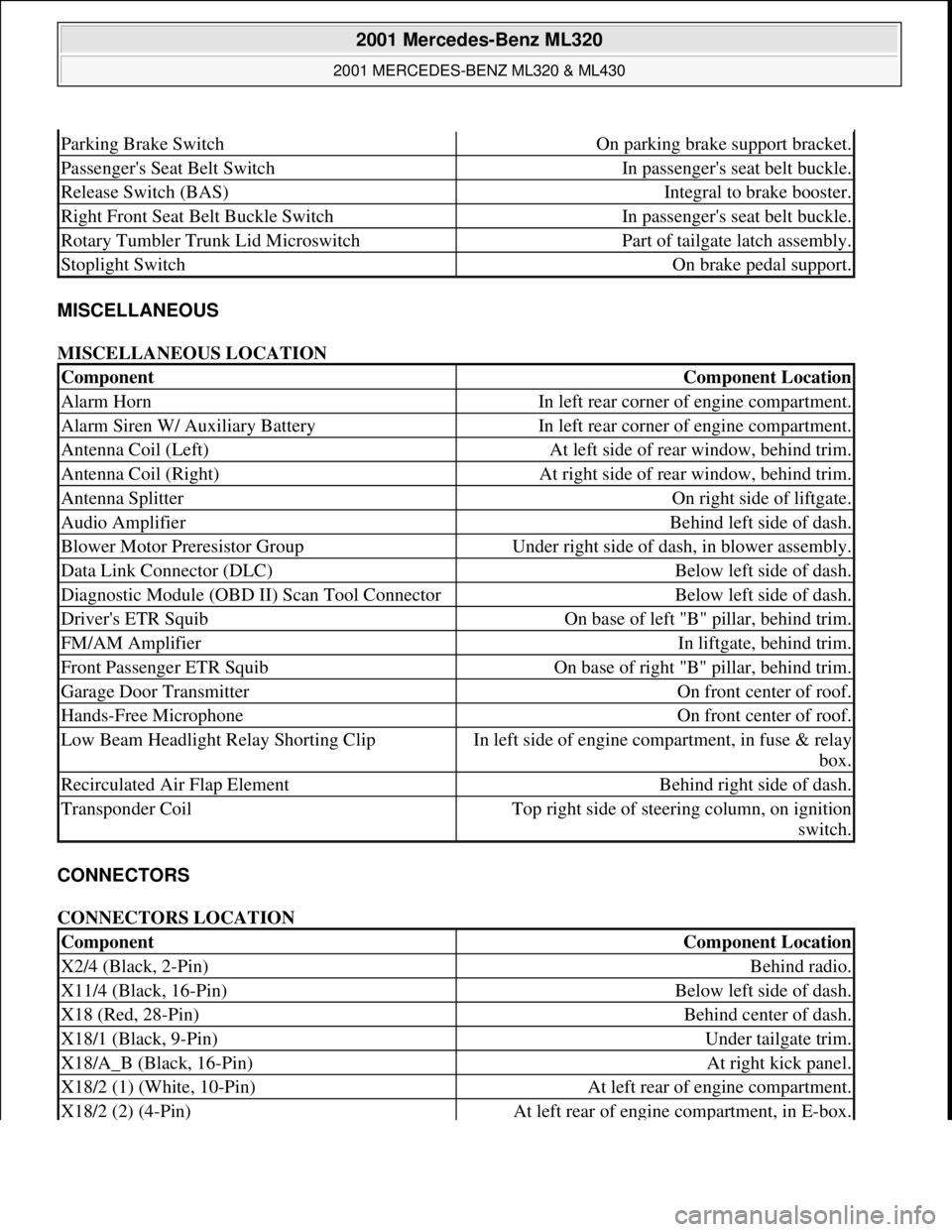
MISCELLANEOUS
MISCELLANEOUS LOCATION
CONNECTORS
CONNECTORS LOCATION
Parking Brake SwitchOn parking brake support bracket.
Passenger's Seat Belt SwitchIn passenger's seat belt buckle.
Release Switch (BAS)Integral to brake booster.
Right Front Seat Belt Buckle SwitchIn passenger's seat belt buckle.
Rotary Tumbler Trunk Lid MicroswitchPart of tailgate latch assembly.
Stoplight SwitchOn brake pedal support.
ComponentComponent Location
Alarm HornIn left rear corner of engine compartment.
Alarm Siren W/ Auxiliary BatteryIn left rear corner of engine compartment.
Antenna Coil (Left)At left side of rear window, behind trim.
Antenna Coil (Right)At right side of rear window, behind trim.
Antenna SplitterOn right side of liftgate.
Audio AmplifierBehind left side of dash.
Blower Motor Preresistor GroupUnder right side of dash, in blower assembly.
Data Link Connector (DLC)Below left side of dash.
Diagnostic Module (OBD II) Scan Tool ConnectorBelow left side of dash.
Driver's ETR SquibOn base of left "B" pillar, behind trim.
FM/AM AmplifierIn liftgate, behind trim.
Front Passenger ETR SquibOn base of right "B" pillar, behind trim.
Garage Door TransmitterOn front center of roof.
Hands-Free MicrophoneOn front center of roof.
Low Beam Headlight Relay Shorting ClipIn left side of engine compartment, in fuse & relay
box.
Recirculated Air Flap ElementBehind right side of dash.
Transponder CoilTop right side of steering column, on ignition
switch.
ComponentComponent Location
X2/4 (Black, 2-Pin)Behind radio.
X11/4 (Black, 16-Pin)Below left side of dash.
X18 (Red, 28-Pin)Behind center of dash.
X18/1 (Black, 9-Pin)Under tailgate trim.
X18/A_B (Black, 16-Pin)At right kick panel.
X18/2 (1) (White, 10-Pin)At left rear of engine compartment.
X18/2 (2) (4-Pin)At left rear of engine compartment, in E-box.
2001 Mercedes-Benz ML320
2001 MERCEDES-BENZ ML320 & ML430
me
Saturday, October 02, 2010 3:21:17 PMPage 6 © 2006 Mitchell Repair Information Company, LLC.
Page 2386 of 4133
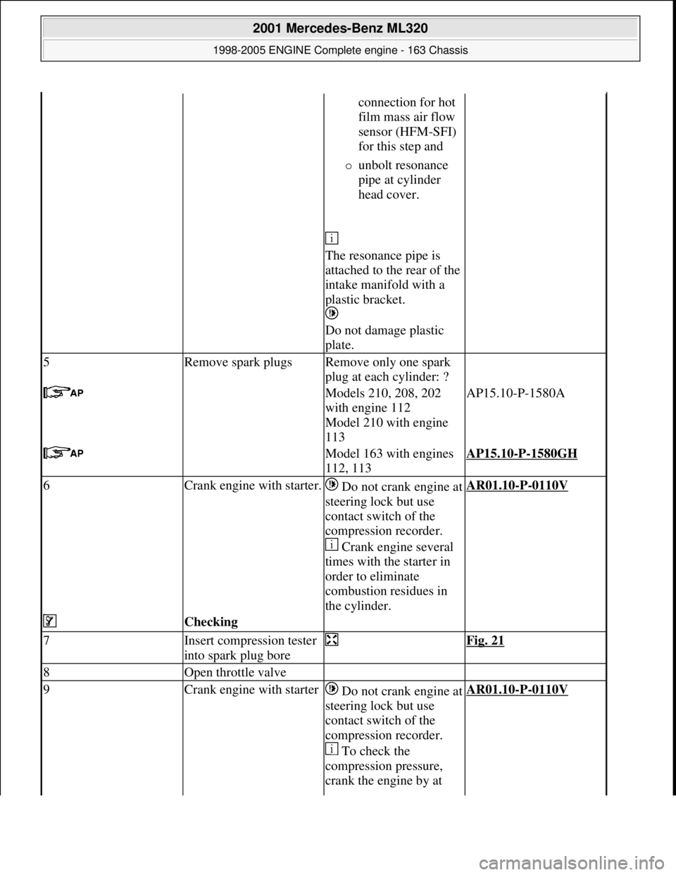
connection for hot
film mass air flow
sensor (HFM-SFI)
for this step and
unbolt resonance
pipe at cylinder
head cover.
The resonance pipe is
attached to the rear of the
intake manifold with a
plastic bracket.
Do not damage plastic
plate.
5Remove spark plugsRemove only one spark
plug at each cylinder: ?
Models 210, 208, 202
with engine 112
Model 210 with engine
113AP15.10-P-1580A
Model 163 with engines
112, 113AP15.10-P-1580GH
6Crank engine with starter.Do not crank engine at
steering lock but use
contact switch of the
compression recorder.
Crank engine several
times with the starter in
order to eliminate
combustion residues in
the cylinder.AR01.10-P-0110V
Checking
7Insert compression tester
into spark plug bore Fig. 21
8Open throttle valve
9Crank engine with starterDo not crank engine at
steering lock but use
contact switch of the
compression recorder.
To check the
compression pressure,
crank the engine by at AR01.10-P-0110V
2001 Mercedes-Benz ML320
1998-2005 ENGINE Complete engine - 163 Chassis
me
Saturday, October 02, 2010 3:17:56 PMPage 30 © 2006 Mitchell Repair Information Company, LLC.
Page 2390 of 4133
covers and sealing ring of the hot
film air mass sensor in the air
filter housing with lubricant.
Models 230.474, 203.065/265,
170.466AR09.10-P-1150SVK
Lubricant
*BR00.45
-Z-1002-
06A
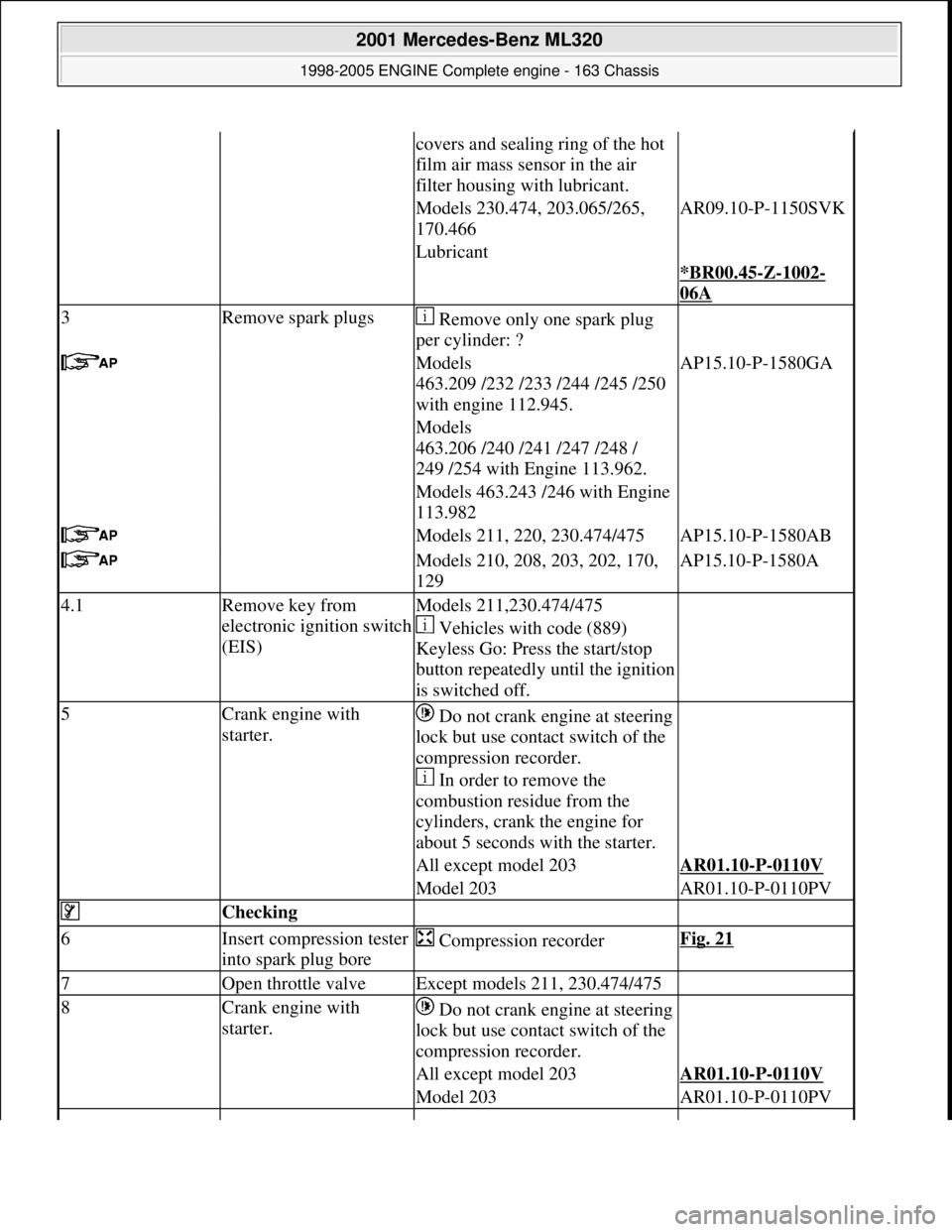
3Remove spark plugs Remove only one spark plug
per cylinder: ?
Models
463.209 /232 /233 /244 /245 /250
with engine 112.945.AP15.10-P-1580GA
Models
463.206 /240 /241 /247 /248 /
249 /254 with Engine 113.962.
Models 463.243 /246 with Engine
113.982
Models 211, 220, 230.474/475AP15.10-P-1580AB
Models 210, 208, 203, 202, 170,
129AP15.10-P-1580A
4.1Remove key from
electronic ignition switch
(EIS)Models 211,230.474/475
Vehicles with code (889)
Keyless Go: Press the start/stop
button repeatedly until the ignition
is switched off.
5Crank engine with
starter. Do not crank engine at steering
lock but use contact switch of the
compression recorder.
In order to remove the
combustion residue from the
cylinders, crank the engine for
about 5 seconds with the starter.
All except model 203AR01.10-P-0110V
Model 203AR01.10-P-0110PV
Checking
6Insert compression tester
into spark plug bore Compression recorderFig. 21
7Open throttle valveExcept models 211, 230.474/475
8Crank engine with
starter. Do not crank engine at steering
lock but use contact switch of the
compression recorder.
All except model 203AR01.10-P-0110V
Model 203AR01.10-P-0110PV
2001 Mercedes-Benz ML320
1998-2005 ENGINE Complete engine - 163 Chassis
me
Saturday, October 02, 2010 3:17:56 PMPage 34 © 2006 Mitchell Repair Information Company, LLC.
Page 2411 of 4133
housing coolant line
--> (17) from
thermostat housing
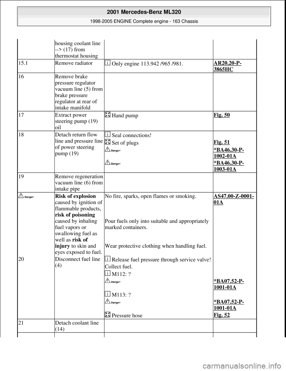
15.1Remove radiator Only engine 113.942 /965 /981.AR20.20-P-
3865HC
16Remove brake
pressure regulator
vacuum line (5) from
brake pressure
regulator at rear of
intake manifold
17Extract power
steering pump (19)
oil Hand pumpFig. 50
18Detach return flow
line and pressure line
of power steering
pump (19) Seal connections!
Set of plugsFig. 51
*BA46.30-P-
1002-01A
*BA46.30-P-
1003-01A
19Remove regeneration
vacuum line (6) from
intake pipe
Risk of explosion
caused by ignition of
flammable products,
risk of poisoning
caused by inhaling
fuel vapors or
swallowing fuel as
well as risk of
injury to skin and
eyes exposed to fuel.No fire, sparks, ope n flames or smoking.AS47.00-Z-0001-
01A
Pour fuels only into suitable and appropriately
marked containers.
Wear protective clothing when handling fuel.
20Disconnect fuel line
(4) Release fuel pressure through service valve!
Collect fuel.
M112: ?
*BA07.52-P-
1001-01A
M113: ?
*BA07.52-P-
1001-01A
Pressure hoseFig. 52
21Detach coolant line
(14)
2001 Mercedes-Benz ML320
1998-2005 ENGINE Complete engine - 163 Chassis
me
Saturday, October 02, 2010 3:17:56 PMPage 55 © 2006 Mitchell Repair Information Company, LLC.