Page 105 of 227
. If battery voltage does
not exist, check the circuit from the ignition ON
relay to the battery (refer to the wiring diagrams
at")
9Check for battery voltage to the Ignition ON
relay (see illustration). If battery voltage does
not exist, check the circuit from the ignition ON
relay to the battery (refer to the wiring diagrams
at the end of Chapter 12). Note:See Chapter 12
for the location of the Ignition ON relay.
10Check the operation of the crankshaft
position sensor (see Chapter 6).
11If all the checks are correct, check the
voltage signal from the computer. Using an LED
type test light, backprobe the coil power lead
(negative terminal) on the ignition coil (see
illustration). Remove the coil secondary wire
and earth the terminal to the engine. Now have
an assistant crank the engine over and observe
that the test light pulses on and off. If there is no
flashing from the test light, most likely the
computer is damaged. Have the ECU diagnosed
by a dealer service department.
12Additional checks should be performed by a
dealer service department or an automotive
repair workshop.
7 Amplifier- check and renewal
2
Warning: Because of the high
voltage generated by the
ignition system, extreme care
should be taken whenever an
operation is performed involving ignitioncomponents. This not only includes the
amplifier, coil, distributor and spark plug
leads, but related components such as
connectors, tachometer and other test
equipment also.
Note:Because of the complexity and the
special tools required to test the amplifier, the
following procedure only describes a test to
verify battery voltage is reaching the amplifier.
If the wiring harness and the relays are
working properly and battery voltage is
available to the amplifier, have the ignition
system and the ECU diagnosed by a dealer
service department.
Check
1Disconnect the amplifier electrical connector
(see illustration).
2Turn the ignition key ON (engine not
running), check for battery voltage (see
illustration) to the amplifier.
3If no battery voltage is present, check the
harness from the ignition switch to the
amplifier. Refer to the wiring diagrams at the
end of Chapter 12.
Renewal
4Disconnect the negative battery terminal.
Caution: If the stereo in your vehicle is
equipped with an anti-theft system, make
sure you have the correct activation code
before disconnecting the battery.5Remove the amplifier mounting bolts (see
illustration).
6Refitting is the reverse of removal.
8 Ignition coil-
check and renewal
2
Check
1Detach the cable from the negative terminal
of the battery.
Caution: If the stereo in your vehicle is
equipped with an anti-theft system, make
Engine electrical systems 5•3
5
6.5 Check for battery voltage to the
coil (+) terminal6.9 Check for battery voltage
to the IGN ON relay6.11 Refit the LED test light to the coil
negative (-) terminal, crank the engine over
and observe the light flash in response to
the trigger signal from the computer
7.1 Remove the clip that retains the
harness connector to the amplifier7.2 Check for battery voltage to the
ignition amplifier
7.5 Remove the amplifier mountings
screws (arrowed) and lift the unit from the
engine compartment
3261 Jaguar XJ6
Page 106 of 227
 Me")
sure you have the correct activation code
before disconnecting the battery.
2Disconnect the electrical connectors and
the coil wire from the coil.
3Using an ohmmeter, check the coil
resistance:
a) Measure the resistance between the
positive and negative terminals (see
illustration). Compare your reading with
the specified coil primary resistance listed
in this Chapter’s Specifications.
b) Measure the resistance between the
positive terminal and the high tension (HT)
terminal(see illustration). Compare your
reading with the specified coil secondary
resistance listed in this Chapter’s
Specifications.
4If either of the above tests yield resistance
values outside the specified amount, renew
the coil.
Renewal
5Detach the battery negative cable.
Caution: If the stereo in your vehicle is
equipped with an anti-theft system, make
sure you have the correct activation code
before disconnecting the battery. 6Label and disconnect the electrical wires
from the coil terminals.
7Remove the coil mounting fasteners (see
illustration).
8Refitting is the reverse of removal.
9 Distributor-
removal and refitting
2
Note:The timing on this ignition system cannot
be adjusted by turning the distributor. Ignition
timing is maintained by the ECU at all times. In
the event the distributor must be removed from
the engine, be sure to follow the precautions
described in this section and mark the engine
and distributor with paint to ensure correct
refitting. If the distributor is not marked, and the
crankshaft is turned while the distributor is out of
the engine, have the distributor installed by a
dealer service department. The distributor must
be installed using a special alignment tool.
Removal
1Detach the battery negative cable. Caution: If the stereo in your vehicle is
equipped with an anti-theft system, make
sure you have the correct activation code
before disconnecting the battery.
2Disconnect the electrical connectors from
the distributor.
3Look for a raised “1” on the distributor cap.
This marks the location for the number one
cylinder spark plug lead terminal. If the cap
does not have a mark for the number one
terminal, locate the number one spark plug
and trace the wire back to the terminal on the
cap.
4Remove the distributor cap (see Chapter 1)
and rotate the engine until the rotor is pointing
toward the number one spark plug terminal.
5Make a mark on the edge of the distributor
base directly below the rotor tip and in line
with it. Also, mark the distributor base and the
engine block to ensure that the distributor is
installed correctly (see illustrations).
6Remove the distributor hold-down bolt,
then pull the distributor out to remove it.
Caution: DO NOT turn the crankshaft while
the distributor is out of the engine, or the
alignment marks will be useless.
5•4 Engine electrical systems
8.3a To check the primary resistance of
the coil, measure the resistance between
the positive and the negative terminals8.3b To check the secondary resistance of
the coil, measure the resistance between
the positive terminal and the HT terminal8.7 Remove the nuts from the coil
mounting bracket (arrowed)
3261 Jaguar XJ6
9.5a Paint or scribe a mark (arrowed) on the edge of the
distributor housing below the rotor tip to ensure that the rotor is
pointing in the same direction when the distributor is reinstalled9.5b Paint or scribe another mark across the cylinder head and
the distributor body (arrowed) to ensure that the distributor is
aligned correctly when it is reinstalled
Page 107 of 227

Refitting
7Insert the distributor into the engine in
exactly the same relationship to the block that
it was in when removed.
8If the distributor does not seat completely,
recheck the alignment marks between the
distributor base and the block to verify that
the distributor is in the same position it was in
before removal. Also check the rotor to see if
it’s aligned with the mark you made on the
edge of the distributor base.
9Refit the distributor hold-down bolt(s).
10The remainder of refitting is the reverse of
removal.
10 Charging system- general
information and precautions
The charging system includes the alternator,
an internal voltage regulator, a charge
indicator light, load dump module, the battery,
an ignition ON relay, an in-line fuse and the
wiring between all the components (see
illustration). The charging system supplies
electrical power for the ignition system, the
lights, the radio, etc. The alternator is driven by
a drivebelt at the front of the engine.
The purpose of the voltage regulator is to
limit the alternator’s voltage to a preset value.
This prevents power surges, circuit overloads,
etc., during peak voltage output.
The alternator load dump module protects
the electrical circuits from excessive voltage
surges. When the battery cables are removed
large amounts of transient voltage is released
through the electrical circuits. This device
diverts up to 30 load volts of excess voltage to
earth by way of a voltage dependent resistor.
The in-line fuse is a special fuse installed
into the circuit with the engine compartment
wiring harness (see Chapter 12). The in-line
fuse protects the electrical system in the
event of excess voltage surges or a power to
earth short circuit. Refer to Chapter 12 for
additional information concerning the in-line
fuses and their locations.
1993 and 1994 models have a Starter Logic
Relay. This microprocessor (computer)
gathers information from the ignition switch,
linear gear position switch, park/neutral
switch, the security switch and the electronic
door lock system. If all the conditions are in
order, the computer allows battery voltage to
be transferred from the ignition switch to the
starter/solenoid assembly.
The charging system doesn’t ordinarily
require periodic maintenance. However, the
drivebelt, battery and wires and connections
should be inspected at the intervals outlined
in Chapter 1.
The dashboard warning light should come
on when the ignition key is turned to Start,
then should go off immediately. If it remains
on, there is a malfunction in the charging
system. Some vehicles are also equipped with
a voltage gauge. If the voltage gaugeindicates abnormally high or low voltage,
check the charging system (see Section 11).
Be very careful when making electrical
circuit connections to a vehicle equipped with
an alternator and note the following:
a) When reconnecting wires to the alternator
from the battery, note their polarity.
b) Before using arc welding equipment to
repair any part of the vehicle, disconnect
the wires from the alternator and the
battery terminals.
c) Never start the engine with a battery
charger connected.
d) Always disconnect both battery leads
before using a battery charger.
e) The alternator is driven by an engine
drivebelt which could cause serious injury
if your hand, hair or clothes become
entangled in it with the engine running.
f) Because the alternator is connected
directly to the battery, it could arc or
cause a fire if overloaded or shorted out.
g) Wrap a plastic bag over the alternator and
secure it with rubber bands before steam
cleaning the engine.
11 Charging system- check
2
Note:1993 and 1994 models are equipped
with a Starter Logic Relay. This microprocessor
(computer) gathers information from theignition switch, linear gear position switch,
park/neutral switch, the security switch and the
electronic door lock system. If all the conditions
are in order, the computer allows battery
voltage to be transferred from the ignition
switch to the starter/solenoid assembly. If all
the components of the charging system are
working properly and the system still does not
charge properly, have the Starter Logic Relay
diagnosed by a dealer service department.
1If a malfunction occurs in the charging
circuit, don’t automatically assume that the
alternator is causing the problem. First check
the following items:
a) Check the drivebelt tension and its
condition. Renew it if worn or damaged.
b) Make sure the alternator mounting and
adjustment bolts are tight.
c) Inspect the alternator wiring harness and
the electrical connectors at the alternator
and voltage regulator. They must be in
good condition and tight.
d) Check the fusible link (if equipped)
located between the starter solenoid and
the alternator or the large main fuses in
the engine compartment. If it’s burned,
determine the cause, repair the circuit
and renew the link or fuse (the vehicle
won’t start and/or the accessories won’t
work if the fusible link or fuse blows).
e) Check all the in-line fuses that are in series
with the charging system circuit (see
Chapter 12).The location of these fuses
and fusible links may vary from year and
Engine electrical systems 5•5
5
10.1 Schematic of a typical charging system
3261 Jaguar XJ6
Page 108 of 227
 Start the engine and check the alternator
for abnormal noises (a shrieking or
squealing sound indicat")
model but the designations are the same.
Refer to the wiring diagrams at the end of
Chapter 12.
f) Start the engine and check the alternator
for abnormal noises (a shrieking or
squealing sound indicates a bad bushing).
g) Check the specific gravity of the battery
electrolyte. If it’s low, charge the battery
(doesn’t apply to maintenance free
batteries).
h) Make sure that the battery is fully charged
(one bad cell in a battery can cause
overcharging by the alternator).
i) Disconnect the battery cables (negative
first, then positive). Caution:If the stereo
in your vehicle is equipped with an anti-
theft system, make sure you have the
correct activation code before
disconnecting the battery. Inspect the
battery posts and the cable clamps for
corrosion. Clean them thoroughly if
necessary (see Chapter 1). Reconnect the
positive cable, then the negative cable.
2Using a voltmeter, check the battery
voltage with the engine off. It should be
approximately 12 volts (see illustration).
3Start the engine and check the battery
voltage again. It should now be approximately
13.5 to 15.1 volts.
4Turn on the headlights. The voltage should
drop and then come back up, if the charging
system is working properly.
5If the voltage reading is greater than the
specified charging voltage, renew the
alternator.
6If you have an ammeter, connect it up to the
charging system according to its maker’s
instructions. If you don’t have a professional-
type ammeter, you can also use an inductive-
type current indicator. This device is
inexpensive, readily available at car accessory
outlets and accurate enough to perform simple
amperage checks like the following test.7With the engine running at 2000 rpm, check
the reading on the ammeter with all
accessories and lights off (no load), then again
with the high-beam headlights on and the
heater blower switch turned to the HI position
(full load). Compare your readings to the
standard amperage listed in this Chapter’s
Specifications.
8If the ammeter reading is less than standard
amperage, repair or renew the alternator.
9If the alternator is working but the charging
system still does function properly, check the
operation of the load dump module (see
illustration). Have this component checked at
a dealer service department.
12 Alternator-
removal and refitting
2
1Detach the cable from the negative terminal
of the battery.
Caution: If the stereo in your vehicle is
equipped with an anti-theft system, make
sure you have the correct activation code
before disconnecting the battery.2Detach the electrical connectors from the
alternator.
3Loosen the alternator adjustment and pivot
bolts (see illustration) and detach the
drivebelt.
4Remove the adjustment and pivot bolts
(see illustration)from the alternator
adjustment bracket.
5If you are replacing the alternator, take the
old alternator with you when purchasing a
replacement unit. Make sure that the
new/rebuilt unit is identical to the old
alternator. Look at the terminals - they should
be the same in number, size and locations as
the terminals on the old alternator. Finally,
look at the identification markings - they will
be stamped in the housing or printed on a tag
or plaque affixed to the housing. Make sure
that these numbers are the same on both
alternators.
6Many new/rebuilt alternators do not have
a pulley installed, so you may have to switch
the pulley from the old unit to the new/rebuilt
one. When buying an alternator, find out the
policy regarding refitting of pulleys - some
shops will perform this service free of charge.
7Refitting is the reverse of removal.
5•6 Engine electrical systems
12.3 Loosen the lock bolt and back-off
the adjustment bolt (arrowed) to remove
the drivebelt12.4 Remove the pivot bolt and nut
3261 Jaguar XJ6 11.2 Connect the probes of a voltmeter to the battery terminals
and observe battery voltage with the engine OFF
and then with the engine running
11.9 The load dump module is located on the bulkhead
next to the MAF sensor
Page 109 of 227
.
9Check the charging voltage to verify proper
operation of the alternator (see Section 11).
13 Starting system- general")
8After the alternator is installed, adjust the
drivebelt tension (see Chapter 1).
9Check the charging voltage to verify proper
operation of the alternator (see Section 11).
13 Starting system- general
information and precautions
The sole function of the starting system is
to crank the engine over quickly enough to
allow it to start.
The starting system consists of the battery,
the starter motor, the starter solenoid, the
starter relay and the electrical circuit
connecting the components. The solenoid is
mounted directly on the starter motor.
The solenoid/starter motor assembly is
installed on the upper part of the engine, next
to the transmission bellhousing.
When the ignition key is turned to the
START position, the starter solenoid is
actuated through the starter control circuit.
The starter solenoid then connects the battery
to the starter. The battery supplies the
electrical energy to the starter motor, which
does the actual work of cranking the engine.
The starter on a vehicle equipped with an
automatic transmission can be operated only
when the transmission selector lever is in Park
or Neutral.
These vehicles are equipped with either a
Bosch or Lucas starter assembly. The Lucas
unit is distinguished by the separate earth
strap from the solenoid to the starter body.
Bosch starter assemblies are equipped with a
solid metal earthing bar.
The starting system circuit is equipped with
a relay. The relay allows the ignition switch to
power the starter solenoid.
Always observe the following precautions
when working on the starting system:
a) Excessive cranking of the starter motor
can overheat it and cause serious
damage. Never operate the starter motor
for more than 15 seconds at a time
without pausing to allow it to cool for at
least two minutes.
b) The starter is connected directly to the
battery and could arc or cause a fire if
mishandled, overloaded or short circuited.
c) Always detach the cable from the
negative terminal of the battery before
working on the starting system.
Caution:If the stereo in your vehicle is
equipped with an anti-theft system, make
sure you have the correct activation code
before disconnecting the battery.
14 Starter motor-
testing in vehicle
2
1Make sure that the battery is charged and
that all cables, both at the battery and starter
solenoid terminals, are clean and secure.2If the starter motor does not turn at all when
the switch is operated, make sure that the
shift lever is in Neutral or Park (automatic
transmission) or that the clutch pedal is
depressed (manual transmission).
3If the starter motor spins but the engine is
not cranking, the overrunning clutch in the
starter motor is slipping and the starter motor
must be renewed.
4If, when the switch is actuated, the starter
motor does not operate at all but the solenoid
clicks, then the problem lies with either the
battery, the main solenoid contacts or the
starter motor itself (or the engine is seized).
5If the solenoid plunger cannot be heard
when the switch is actuated, the battery is
bad, the in-line fuse is burned (the circuit is
open), the starter relay (see illustration)is
defective or the starter solenoid itself is
defective.
6To check the solenoid, connect a jumper
lead between the battery (+) and the ignition
switch terminal (the small terminal) on the
solenoid. If the starter motor now operates,
the solenoid is OK and the problem is in the
ignition switch, linear switch (1988 to 1992),
rotary switch (1993 and 1994) or in the wiring.
7If the starter motor still does not operate,
remove the starter/solenoid assembly for
dismantling, testing and repair.
8If the starter motor cranks the engine at an
abnormally slow speed, first make sure that
the battery is charged and that all terminalconnections are tight. If the engine is partially
seized, or has the wrong viscosity oil in it, it
will crank slowly.
9Run the engine until normal operating
temperature is reached, then disconnect the
coil wire from the distributor cap and earth it
on the engine.
10Connect a voltmeter positive lead to the
battery positive post and connect the
negative lead to the negative post.
11Crank the engine and take the voltmeter
readings as soon as a steady figure is
indicated. Do not allow the starter motor to
turn for more than 15 seconds at a time. A
reading of nine volts or more, with the starter
motor turning at normal cranking speed, is
normal. If the reading is nine volts or more but
the cranking speed is slow, the motor is faulty.
If the reading is less than nine volts and the
cranking speed is slow, the solenoid contacts
are probably burned, the starter motor is bad,
the battery is discharged or there is a bad
connection.
15 Starter motor-
removal and refitting
2
1Detach the cable from the negative terminal
of the battery.
Caution: If the stereo in your vehicle is
equipped with an anti-theft system, make
sure you have the correct activation code
before disconnecting the battery.
2Raise the vehicle and support it securely
using axle stands.
3Drain the transmission fluid (see Chapter 7)
and remove the transmission fluid filler tube
from the transmission.
4Detach the electrical connectors from the
starter/solenoid assembly (see illustrations).
5Place a trolley jack under the tail section of
the transmission, remove the rear trans-
mission mount (see Chapter 7) and lower the
transmission slightly to gain access to the
upper transmission bellhousing bolts. Using
an extension with a swivel socket, remove the
upper starter mounting bolt (see illustration).
Engine electrical systems 5•7
5
14.5 With the ignition key ON (engine not
running), check for battery voltage to the
starter relay
15.4a Disconnect the solenoid electrical
connector at the harness connector
located near the bulkhead behind the
cylinder head (arrowed)15.4b From underneath the vehicle,
remove the battery terminal from the
solenoid (cylinder head removed
for clarity)
3261 Jaguar XJ6
Page 110 of 227

6Working forward of the transmission, reach
up into the engine bellhousing area, under the
intake manifold and remove the lower starter
mounting bolt.
7Tilt the starter down and carefully lower the
starter assembly through the front, ahead of
the transmission.
8Refitting is the reverse of removal.16 Starter solenoid-
removal and refitting
2
1Remove the starter motor (see Section 15).
2Scribe or paint a mark across the starter
motor and solenoid assembly.3Disconnect the strap from the solenoid to
the starter motor terminal (if equipped).
4Remove the screws which secure the
solenoid to the starter drive end housing (see
illustration).
5Separate the solenoid from the starter.
6Refitting is the reverse of removal. Be sure
to align the paint or scribe mark.
5•8 Engine electrical systems
3261 Jaguar XJ6 15.5 The upper starter bolt can be reached from underneath the
vehicle using a long extension and swivel socket
(cylinder head removed for clarity)
16.4 Remove the three solenoid mounting screws (arrowed) and
separate the solenoid from the starter assembly
Page 111 of 227

3261 Jaguar XJ6
6
Chapter 6
Emissions and engine control systems
EGR gas temperature sensor resistance
Temperature:
212° F . . . . . . . . . . . . . . . . . . . . . . . . . . . . . . . . . . . . . . . . . . . . . . . . . 60 to 100 k-ohms
400° F . . . . . . . . . . . . . . . . . . . . . . . . . . . . . . . . . . . . . . . . . . . . . . . . . 3 to 8 k-ohms
662° F . . . . . . . . . . . . . . . . . . . . . . . . . . . . . . . . . . . . . . . . . . . . . . . . . 250 to 350 ohms
Torque wrench settingNm lbf ft
Crankshaft sensor bolt . . . . . . . . . . . . . . . . . . . . . . . . . . . . . . . . . . . . . . 27 20 Air Injection Reactor (AIR) system . . . . . . . . . . . . . . . . . . . . . . . . . . . 5
Catalytic converter . . . . . . . . . . . . . . . . . . . . . . . . . . . . . . . . . . . . . . . 9
CHECK ENGINE light . . . . . . . . . . . . . . . . . . . . . . . . . . . See Section 3
Crankcase ventilation system . . . . . . . . . . . . . . . . . . . . . . . . . . . . . . 8
Electronic control system and ECU . . . . . . . . . . . . . . . . . . . . . . . . . . 2
Evaporative Emission Control (EVAP) system . . . . . . . . . . . . . . . . . . 6Exhaust Gas Recirculation (EGR) system . . . . . . . . . . . . . . . . . . . . . 6
Fuel tank cap gasket renewal . . . . . . . . . . . . . . . . . . . . . See Chapter 1
General information . . . . . . . . . . . . . . . . . . . . . . . . . . . . . . . . . . . . . . 1
Information sensors . . . . . . . . . . . . . . . . . . . . . . . . . . . . . . . . . . . . . 4
On Board Diagnosis (OBD) system -
description and fault code access . . . . . . . . . . . . . . . . . . . . . . . . . 3
6•1
Specifications Contents
Easy,suitable for
novice with little
experienceFairly easy,suitable
for beginner with
some experienceFairly difficult,
suitable for competent
DIY mechanic
Difficult,suitable for
experienced DIY
mechanicVery difficult,
suitable for expert DIY
or professional
Degrees of difficulty
54321
1 General information
To minimise pollution of the atmosphere
from incompletely burned and evaporating
gases and to maintain good driveability and
fuel economy, a number of emission control
systems are used on these vehicles. They
include the:
Air Injection Reactor (AIR) system
Crankcase Ventilation system
Exhaust Gas Recirculation (EGR) system
Electronic Fuel Injection (EFI) system
Evaporative Emission Control (EVAP)
system
Three-way catalytic converter (TWC)
system
The sections in this chapter include general
descriptions, checking procedures within the
scope of the home mechanic and component
renewal procedures (when possible) for each
of the systems listed above.
Before assuming an emissions control
system is malfunctioning, check the fuel and
ignition systems carefully (Chapters 4 and 5).
The diagnosis of some emission control
devices requires specialised tools, equipment
and training. If checking and servicing becometoo difficult or if a procedure is beyond the
scope of your skills, consult your dealer
service department or other repair workshop.
This doesn’t mean, however, that emission
control systems are particularly difficult to
maintain and repair. You can quickly and
easily perform many checks and do most of
the regular maintenance at home with
common tune-up and hand tools. Note:The
most frequent cause of emission problems is
simply a loose or broken electrical connector
or vacuum hose, so always check the
electrical connectors and vacuum hoses first.Pay close attention to any special
precautions outlined in this chapter. It should
be noted that the illustrations of the various
systems may not exactly match the system
installed on your vehicle because of changes
made by the manufacturer during production
or from year-to-year.
The Vehicle Emissions Control Information
(VECI) label and a vacuum hose diagram are
located under the bonnet (see illustrations).
These contain important emissions specifi-
cations and setting procedures, and a
vacuum hose schematic with emissions
1.6a The Vehicle Emissions Control
Information (VECI) label shows the types of
emission control systems installed, engine
information, etc (1992 model shown)
1.6b Typical vacuum hose routing label
(1992 model shown)
Page 112 of 227

components identified. When servicing the
engine or emissions systems, the VECI label
in your particular vehicle should always be
checked for up-to-date information.
2 Electronic control system
and ECU
General description
Note: These models are susceptible to ECU
damage if water is allowed to build up in the
front cowl drain and overspill into the dash
area near the computer. Inspect and clear the
front cowl drain as a regular maintenance item
to keep the water draining properly. Remove
the duckbill-type rubber hose and inspect it
for clogging, collapsing or deterioration.
1The Lucas LH Engine Management system
controls the fuel injection system by means of
a microcomputer known as the Electronic
Control unit (ECU).
2The ECU receives signals from various
sensors which monitor changing engine
operating conditions such as intake air mass,
intake air temperature, coolant temperature,
engine rpm, acceleration/deceleration,
exhaust oxygen content, etc. These signals
are utilised by the ECU to determine the
correct injection duration.
3The system is analogous to the central
nervous system in the human body: The
sensors (nerve endings) constantly relay
signals to the ECU (brain), which processes
the data and, if necessary, sends out a
command to change the operating
parameters of the engine (body).
4Here’s a specific example of how one
portion of this system operates: An oxygen
sensor, located in the exhaust manifold,
constantly monitors the oxygen content of the
exhaust gas. If the percentage of oxygen in
the exhaust gas is incorrect, an electrical
signal is sent to the ECU. The ECU takes this
information, processes it and then sends a
command to the fuel injection system telling it
to change the air/fuel mixture. This happens in
a fraction of a second and it goes on
continuously when the engine is running. The
end result is an air/fuel mixture ratio which is
constantly maintained at a predetermined
ratio, regardless of driving conditions.
5In the event of a sensor malfunction, a
backup circuit will take over to provide
driveability until the problem is identified and
fixed.
Precautions
6Follow these steps:
a) Always disconnect the power by either
turning off the ignition switch or
disconnecting the battery terminals before
removing electrical connectors.
Warning: Later models are
equipped with airbags. To
prevent accidental deployment ofthe airbag, which could cause personal
injury, DO NOT work in the vicinity of the
steering column or instrument panel. The
manufacturer recommends that, on airbag
equipped models, the following procedure
should be left to a dealer service
department or other repair workshop
because of the special tools and techniques
required to disable the airbag system.
Caution: If the stereo in your vehicle is
equipped with an anti-theft system, make
sure you have the correct activation code
before disconnecting the battery.
b) When refitting a battery, be particularly
careful to avoid reversing the positive and
negative battery cables. Also, make sure
the ignition key is in the Off position when
connecting or disconnecting the battery.
c) Do not subject EFI components,
emissions-related components or the
ECU to severe impact during removal or
refitting.
d) Do not be careless during fault diagnosis.
Even slight terminal contact can invalidate
a testing procedure and damage one of
the numerous transistor circuits.
e) Never attempt to work on the ECU or
open the ECU cover. The ECU is
protected by a government-mandated
extended warranty that will be nullified if
you tamper with or damage the ECU.
f) If you are inspecting electronic control
system components during rainy weather,
make sure that water does not enter any
part. When washing the engine
compartment, do not spray these parts or
their electrical connectors with water.
g) These models are susceptible to ECU
damage if water is allowed to build up in
the front cowl drain and overspill into the
dash area. Inspect and clear the front
cowl drain system as a regular
maintenance item to keep the water
draining properly. Remove the duckbill
type rubber hose and inspect it for
clogging, collapsing or deterioration.
ECU removal and refitting
7Disconnect the negative cable from the
battery (see Chapter 5).
Warning: Later models are
equipped with airbags. To
prevent the accidental deploy-
ment of the airbag, which could
cause personal injury, DO NOT work in the
vicinity of the steering column or
instrument panel. The manufacturer
recommends that, on airbag equipped
models, the following procedure should be
left to a dealer service department or other
repair workshop because of the special
tools and techniques required to disable
the airbag system.
Caution: If the stereo in your vehicle is
equipped with an anti-theft system, make
sure you have the correct activation code
before disconnecting the battery.8Remove the lower instrument panel on the
passenger side under the glove compartment
(see Chapter 11).
9Remove the glove compartment from the
passenger compartment (see Chapter 11).
10Remove the screws from the ECU bracket
(see illustration).
11Lower the ECU and unplug the electrical
connectors.
12Refitting is the reverse of removal.
3 On Board Diagnosis (OBD)
system- description and fault
code access
2
Note: 1990 and 1991 models may set
Code 69 erroneously. If the battery voltage
drops sufficiently and the ignition key is
switched quickly from OFF to START, battery
voltage will be lowered and during cranking
causing a delayed park/neutral signal from the
decoder module to the ECU. Check all the
battery connections and the condition of the
battery and then check the rotary switch
adjustment in Chapter 7 to remedy this code.
General information
1The ECU contains a built-in self-diagnosis
system which detects and identifies
malfunctions occurring in the network. When
the ECU detects a problem, three things
happen: the CHECK ENGINE light comes on,
the fault is identified and a diagnostic code is
recorded and stored. The ECU stores the
failure code assigned to the specific problem
area until the diagnosis system is cancelled.
Note: 1988 and 1989 models are not
equipped with long term memory. It is
possible to access the codes but the operator
must remember to NOT turn the ignition key to
the OFF position after the CHECK ENGINE
light has been noticed. The codes will be lost
and it will be necessary to start the engine and
operate the vehicle through a complete drive
cycle to allow the fault code(s) to be set once
again. Instead of turning the ignition key to the
OFF position, simply stop at position II (key
ON but engine not running) to retain the fault
codes.
6•2 Emissions and engine control systems
3261 Jaguar XJ6
2.10 The ECU is located behind the
passenger’s side glovebox near the footrest
area. Remove the mounting screws
(arrowed) and carefully lower the ECU
 1
1 2
2 3
3 4
4 5
5 6
6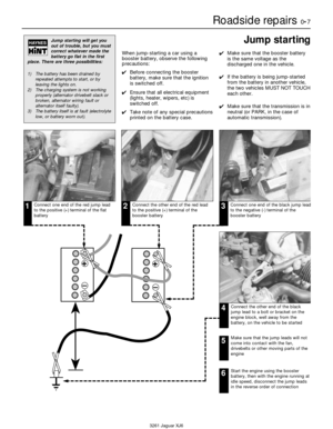 7
7 8
8 9
9 10
10 11
11 12
12 13
13 14
14 15
15 16
16 17
17 18
18 19
19 20
20 21
21 22
22 23
23 24
24 25
25 26
26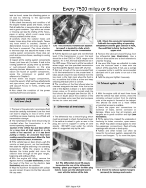 27
27 28
28 29
29 30
30 31
31 32
32 33
33 34
34 35
35 36
36 37
37 38
38 39
39 40
40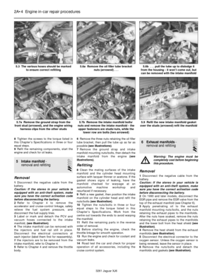 41
41 42
42 43
43 44
44 45
45 46
46 47
47 48
48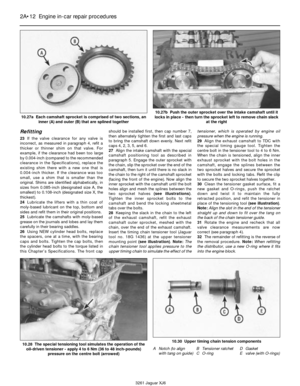 49
49 50
50 51
51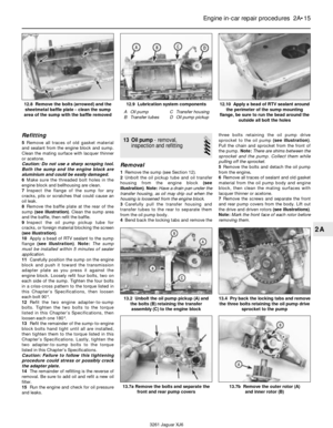 52
52 53
53 54
54 55
55 56
56 57
57 58
58 59
59 60
60 61
61 62
62 63
63 64
64 65
65 66
66 67
67 68
68 69
69 70
70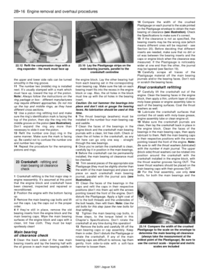 71
71 72
72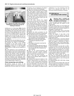 73
73 74
74 75
75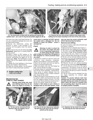 76
76 77
77 78
78 79
79 80
80 81
81 82
82 83
83 84
84 85
85 86
86 87
87 88
88 89
89 90
90 91
91 92
92 93
93 94
94 95
95 96
96 97
97 98
98 99
99 100
100 101
101 102
102 103
103 104
104 105
105 106
106 107
107 108
108 109
109 110
110 111
111 112
112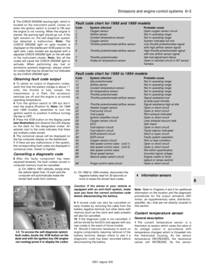 113
113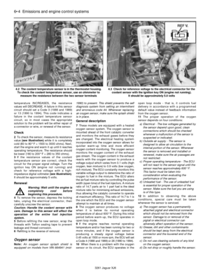 114
114 115
115 116
116 117
117 118
118 119
119 120
120 121
121 122
122 123
123 124
124 125
125 126
126 127
127 128
128 129
129 130
130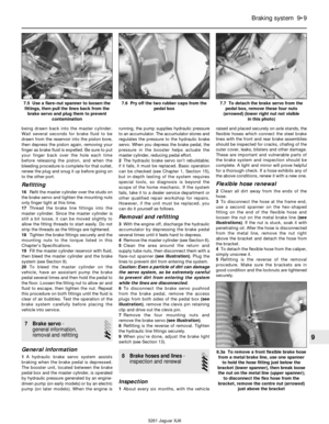 131
131 132
132 133
133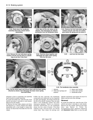 134
134 135
135 136
136 137
137 138
138 139
139 140
140 141
141 142
142 143
143 144
144 145
145 146
146 147
147 148
148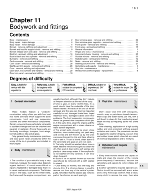 149
149 150
150 151
151 152
152 153
153 154
154 155
155 156
156 157
157 158
158 159
159 160
160 161
161 162
162 163
163 164
164 165
165 166
166 167
167 168
168 169
169 170
170 171
171 172
172 173
173 174
174 175
175 176
176 177
177 178
178 179
179 180
180 181
181 182
182 183
183 184
184 185
185 186
186 187
187 188
188 189
189 190
190 191
191 192
192 193
193 194
194 195
195 196
196 197
197 198
198 199
199 200
200 201
201 202
202 203
203 204
204 205
205 206
206 207
207 208
208 209
209 210
210 211
211 212
212 213
213 214
214 215
215 216
216 217
217 218
218 219
219 220
220 221
221 222
222 223
223 224
224 225
225 226
226